group assignment: compare the performance and development workflows for other architectures
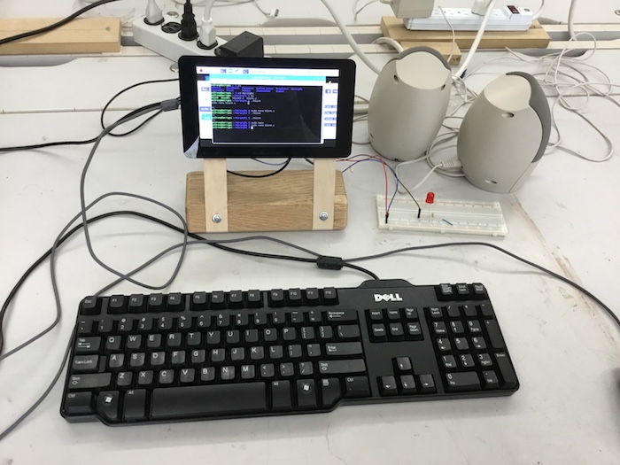
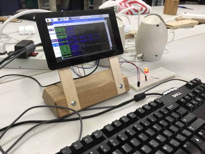
Since this week introduced very new information for us, we decided to try only one architecture: raspberry pi with C code. We used this noobs tutorial to get the raspberry pi set up and hooked up to a moniter. Essentially, we loaded a bootloader on sd card, put sd card into pi and start up the pi board. the bootloader loads an operating system (a specialized version of linux) onto the pi. We then used this WiringPi tutorialto make an LED blink. First, we opened up the terminal window. Here are the commands we used in terminal:
mkdir WiringPi
This created a folder called Wiring Pi
cd WiringPi
sudo nano
this takes you to a text editor
add code to text editor and saved c file as blink
gcc -wall -o blink blink.c -lwiringPi
this compiles the code, translating it to the machine code
./blink
to load the code to the raspberry pi
control c
individual assignment: read a microcontroller data sheet
program your board to do something,
with as many different programming languages
and programming environments as possible
I have virtually no electronic programming experience so this was quite a learning experience. Here is what I learned from Neil's video and some other research:
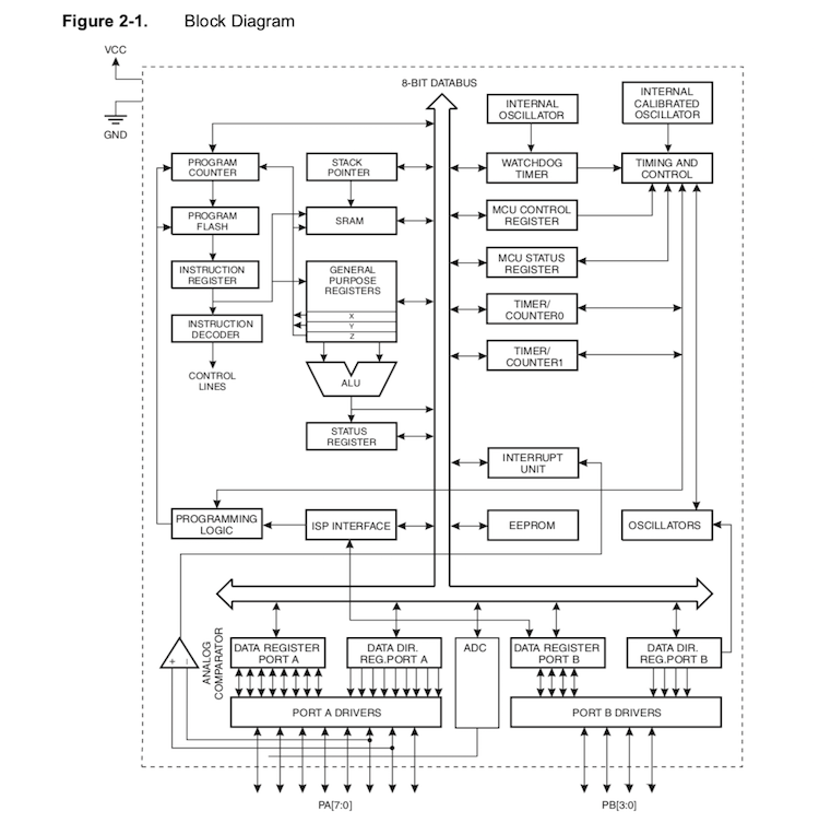
Hardware: A microcontroller contains a processor, also called a microprocessor, which is a small chip frequently found in computers whose job is to receive input and provide an output. A processer only has a CPU inside it while microcontrollers contain the processor in addition to RAM, ROM, and other parts. The way the parts of a microcontroller are arranged is called architecture. The parts aside from the processor in a microcontroller are called peripherals. I learned this with the help of looking at the microcontroller data sheet.
In system development refers to how we hook up the microcontroller to the computer to load code onto it. So ISP (in system programmer) means using a programmer attached to the board which is in turn powered by the computer. Conversely, arduino only requires you to burn the bootloader, using the board itself as a programmer.
Software: an IDE (integrated development environment) is a piece of software that acts as a text editor, debugger, and compiler for code. Examples of IDEs I am now familiar with include Arduino, Scratch, and Modkit. Oftentimes we have to upload certain libraries that are files written in C or C++ which provide sketches with extra functionality. The code we put into the IDE can be assembly language (which is the most basic) such as a hex file, C code which is more complicated, or Java or Python which are the highest level.
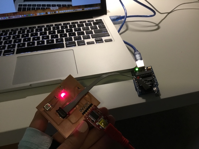
Parts of my board explained: the resistor tells the board to run, the capacitor acts as a filter, the crystal aux board let's the board run faster and more accurately, the header is used to load the program, and the FTDI interface uses TX and RX to show the board is receiving or transmitting.
I used 3 different programming languages/environments: 1)Arduino with C++ 2)C code and makefile using command line 3)winAVR
Arduino
I used this tutorial to program my ATtiny using Arduino. We started with the software component then the hardware.
I first added this url: https://raw.githubusercontent.com/damellis/attiny/ide-1.6.x-boards-manager/package_damellis_attiny_index.json to the Additional Boards manager URLs, then went to Tools--Board--Boards Manager. After scrolling down there was an entry titled ATtiny--I hit install.
After closing the boards manager I went to Tools--Board--clicked ATtiny24/44/84.
Tools--Processor--ATtiny44
Tools--Clock--External 20 MHz
Tools--Port--usbserial...
Tools--Programmer--USBtinyISP
Then we did the hardware component. We attached the microcontroller to the computer, to the programmer, and the programmer to the computer. From there we,
Tools--Burn Bootloader
Opened Blink program from File--Examples. I changed the pins to 7 based on how my board is configured.
Upload the sketch.
C code and Makefile using Command line
I used the same process as I did two weeks ago to upload the code to my microcontroller.
I copied the c code from the fabacademy website and copied and pasted the makefile into a makefile I used previously and put them into a folder entitled Blink.
In my command line in the terminal I cd into the Blink folder.
I ran 'make' which created the .hex file
Hooked up the microcontroller to the programmer and to the computer
Ran 'make program-usbtiny'
Ran 'make program-usbtiny-fuses'
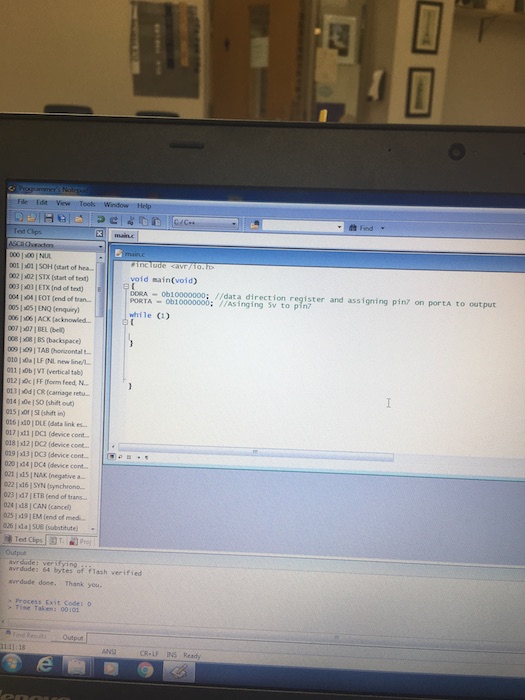
WinAVR using C/C++
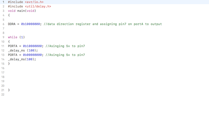
I watched this tutorial to learn how to make an LED blink using winAVR. The first part was to write the c code. We first learned to create the code for a constantly lit LED, then made it blink by adding code inside the "while" function.
Open WinAVR-- programmer's notepad
Change Plaintext to C/C++
Type in all this code into the page!
add this inside the while function for it to blink!
save file and insert it into a folder (that will be created in next part)
The second part was to create a folder and add a makefile to it.
mfile-- Makefile--MCU tpe--ATtiny-attiny44
enable editing of makefile
changing F_CPU from 8000000 to 20000000--> cpu frequency (clock speed)
programmer--abcmini-- change AVRDudeto usbtiny
port--change to usb
change plain text to C/C++
create a folder on the desktop
save makefile to folder
From there we went back to the code and...
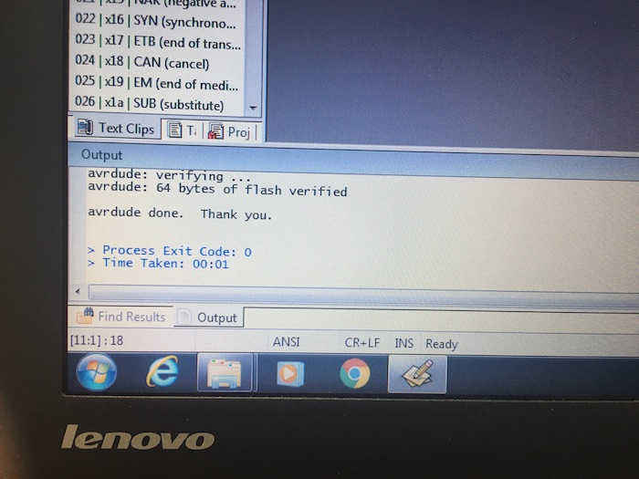
Tools--WinAVR Make All. There should be some text that appears at the bottom of the page to indicate the command worked.
Tools--WinAVR Program. Text should confirm that code uploaded to board.