

Week 15
Machine Design
Group assignment
1 Design a machine that includes mechanism+actuation
+automation
2 Build the mechanical parts and operate it manually
3 Document the group project and your individual contribution
My roles in the group work
1 collecting references for project
2 Doing modification in the central part of machine
3 designing 3d cad model for complete machine
4 laser cutting the design files
5 documentation of electronics part
6 helping teammates in assembly , final testing etc .
Link of files i designed
About this week
In machine design week we all have to work in team to make machine which should have atleast 2axis movement and it include mechanisms+actuation+automation in this mechanisms is a system of parts working together or some linkages connected in a way that they may produce some motion , actuation is set in motion or activate some kind of motion for which we need actuator which are component of a machine that is responsible for moving and controlling a mechanism or system, and automation is automatic control
keeping this things in mind we stared searching ideas on which we together can work ,
Team
The Big Idea
We have decided to make Potter machine, which have interchangeble end-effector such as pen or cutter , and further intending to make this plotter to capture the image and draw the same on paper in real-time for this we use image processing which has explored by adhitiya in his week assignment so we will try to use that but with the limitation of time we finally drop down our plan to make simple pen ploter machine which draw
Referances for the project
for collecting references i suggested to make Google sheet and tanveer made that in which we all share all the links / sources which we found on Internet in this we all can see what other have shared and also create repository of all references
the references which i found
1 cardboard cnc - source link
what good i find
modified mtm kit , rack and pinion mechanisms for uplifting pen
2 mini arduino cnc- source link
what good i find
they used inkspace for gcode generation it support grbl library
3 cnc plottter - source link
what good i find
they made nice acrylic body which we can fabricate easily
they used mobile to control cnc
For understanding workflow i refer previous year student work ex project illumina tea , and nills lecture on machine design As all of us did this same excersise so we found many referances and we get clearity of idea and how to make and prototype with nadya's design
prototyping Nadya's mtm model
Reference design
We finally go with reference of Jonathan K. which we find on thingiverse and his project presentation link we start with this design and doing modification in this
what good about reference which we selected
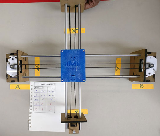
1 we seen many ploters all are having one motor in x axis and another motor in y axis and x axix is on top of y axis as this geometry give instability in design due to load distribution and in this one have both the motors on same axis i.e on y axis and one pully holder and end factor on x axis as we get good static balancing in this structure
Modification in reference design
the reference design have all the parts which have to be 3d printed so we use only central part i.e rods and bearing holder of that for reference design and i did modification in central part and redesign that part also and we made all the other parts using laser cutting.
Designing stages of Machine
As for start designing in cad in 3d , we first print and test the reference design central part and redesign the other parts, laser cut them and first fixed them to check the mechanical movement of machine, in central part we find lots of problem that pully are touching the side wall and and the bearings fixed also have very less distance between them , and it is difficult to insert the hand for taking belt out of central part considering all this changes i started with redesigning the central part in solidworks (as the reference part is in .stl format so i can't edit it ) by taking reference design and removing all the errors in it
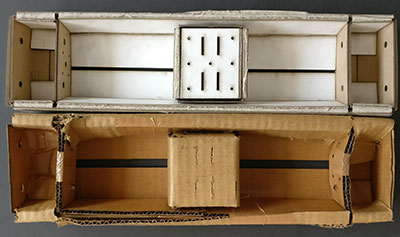
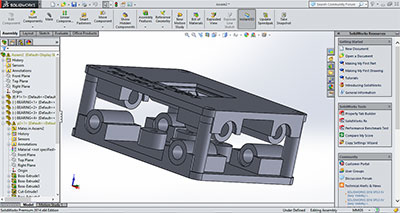
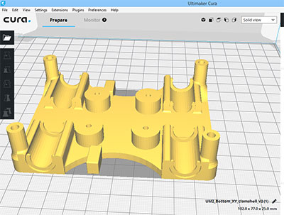
Final design of Central Part
Top Part
Bottom Part
Assembly of Central Part
Comparison of central design part with reference design part
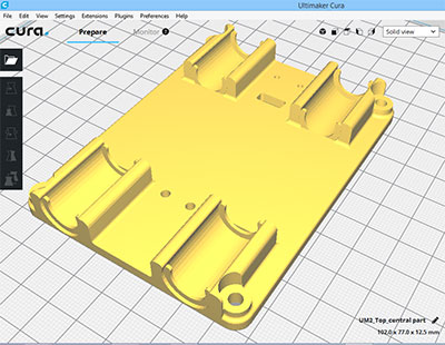
Referance Part top part
Redesigned Part top part
in this there is problem with bearing fitting and distance between bearings also on adjusting the central belt
In this i give slot in central part so we can adust belt in central part and increase bearing holding part size
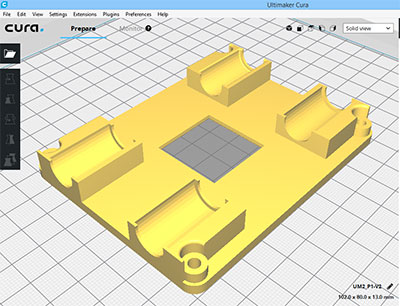
Referance bottom part
Redesigned Bottom Part
in this i adjust the distance between pully holder as we use our own pullys so i changed that as per our requirement
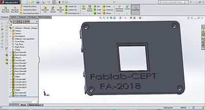
CAD designing of machine
Designing 3d cad model is bit challenging ,i design this in solidworks and also did assembly in that
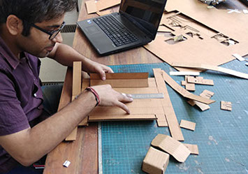
laser cutting the machine Parts
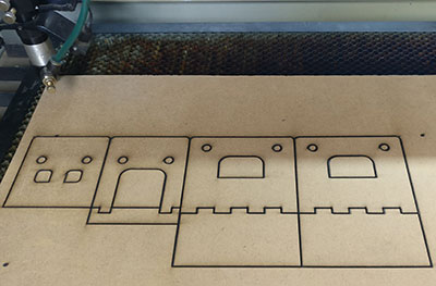
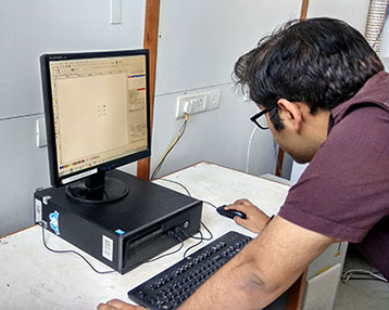
I am involved in laser cutting design files which aditya design we cut that on 5 mm mdf sheet
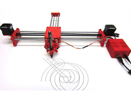
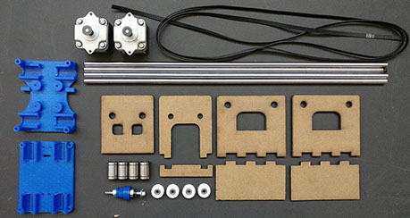
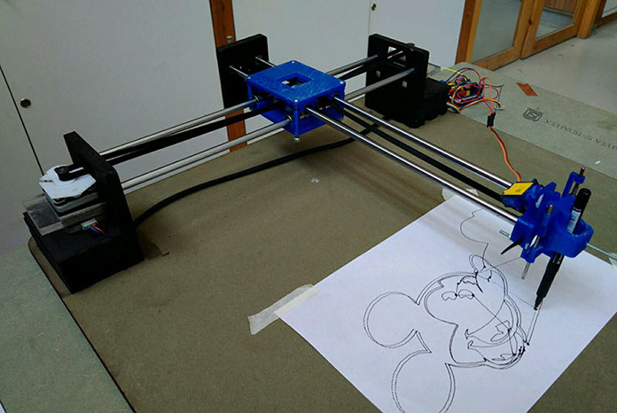
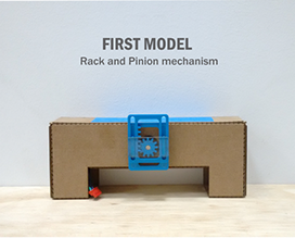
Prototyping of First Model
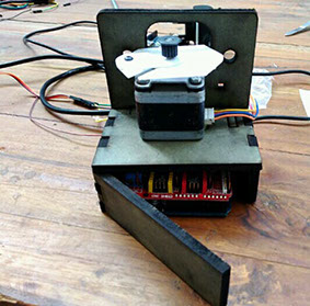
For prototyping we used mdf for side parts i.e motor holding parts , pully holding parts and 3d printed central part the complete things are shown as
Documentation of electronics part
As i was involved in designing and development of machine parts and for understanding electronics i take responsibility of documenting electronics part major contribution in that is of rutuja for finding source and i learn from her for documenting , we use Inkspace for making .ngc file which is numerical g code and arduino with grbl firm ware and universal gcode sender for controlling stepper and sending file for more detail visit our group page
Final model of Machine
FINAL VIDEO OF THIS PROJECT
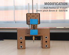
Improvements in Design
1 End factor -in our design one can improve end factor as can make knob for tightening screw, etc,or can improve it to make universal type end factor and attach tools like milling bit for rough cutting of thermacol etc
Make rack and pinion arrangement for uplifting pen more reliable than what we made
2 y axis support / vibration free -in this machine show some vibration in y axis so one can attach wheel in y axis to improve this or one can make this system in aluminum frame so it is more steady and vibration free
3 Make it a kit which can be disassemble and pack in a box for this you need to design this independent of base surface

This work by Gaurav wadhwa is licensed under a Creative Commons Attribution-NonCommercial 4.0 International License.