Output devices
This week's assignment is to Add an output device to a microcontroller board I've designed and program it to do something as an individual project and measure the power consumption of an output device as a group project
There are several parts of this week's projct. first was the circuit design, circuit fabrication then it was the programming.
Circuit design:
- design 1
- design 2
- how to change drill size for through hole components
Circuit production
Programming
Group project: measure the power consumption of an output device
The download links to all the design files and code
circuit design
For an output device I was thinking of different possiblities and options i wanted to work on. there were a lot of options and they all seemed very interesting and that i wanted to create
design 1
I really wanted to create an LED array, but I decided that instead of creating rows of LEDs, I wanted to create something different.
A seven-segment display (SSD), or seven-segment indicator, is a form of electronic display device for displaying decimal numerals that is an alternative to the more complex dot matrix displays.

I wanted to create something of the same effect, but using seperate LEDs arranged in the same shape that i control through the attiny to display numbers (or light them up randomly)
I know that this is not exactly the same principle of a seven segament, but think of this as an LED array arranged in an unusual way.
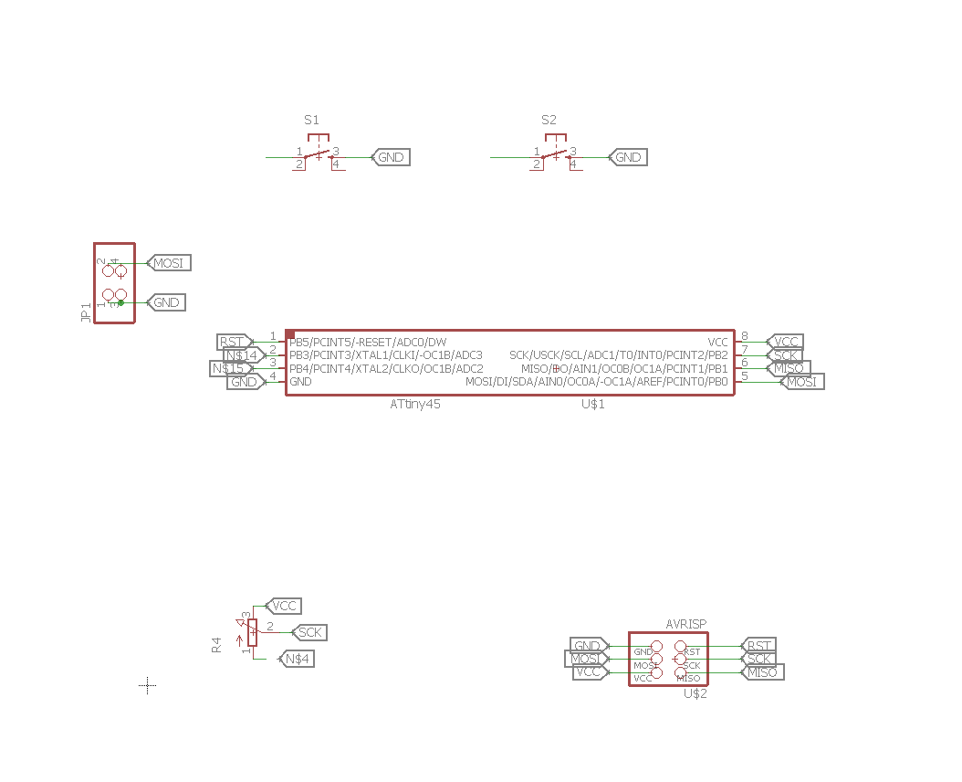
I started by designing the circuit in eagle and connectiong 7 LEDs to my attiny in the schematic

Next was creating a PCB board using eagle
I arranged the LEDs in the shape that I wanted to create the effect. connecting it all up however proved to be a little diffecult becuase of the unique arrangmet of the LEDs and obviously I could not move them.
The connections below were made using the autorouter
Design 2
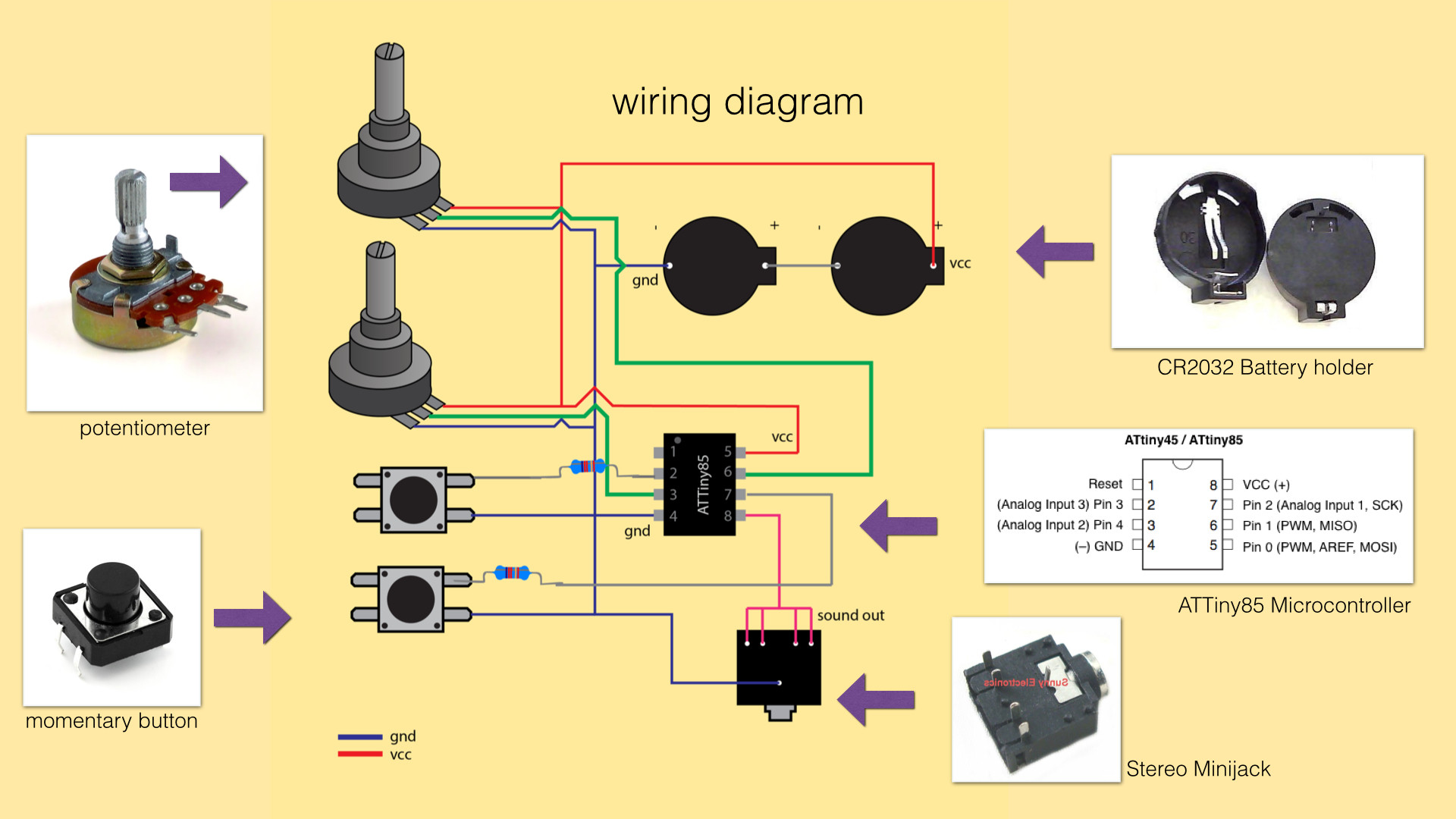
I wanted to test connecting a speaker to the attiny. Salman showed me this video and i really wanted to make something of this sort
this is a part of an open source project called 8-bit mixtape
8-bit Mixtape is a small compatible synthesizer running on an attiny85 with very basic components
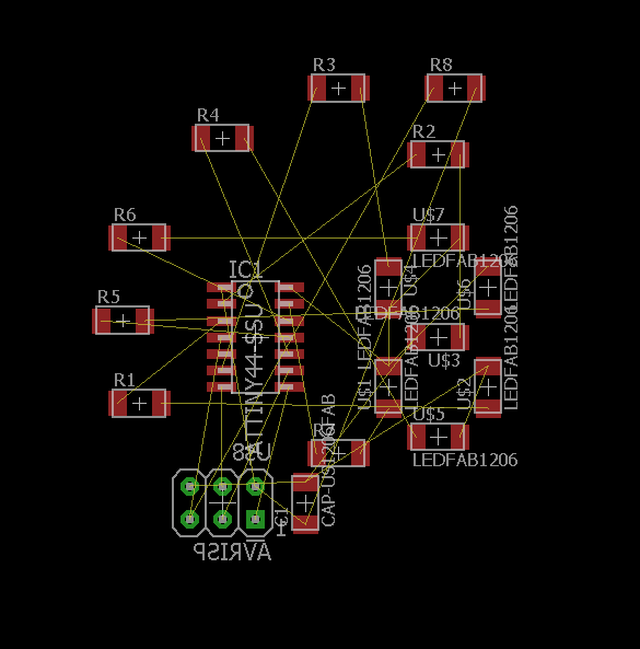
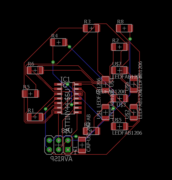
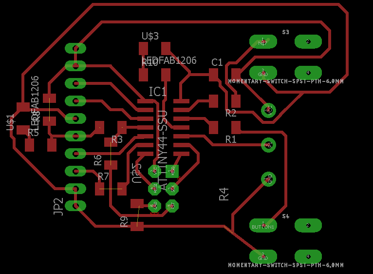
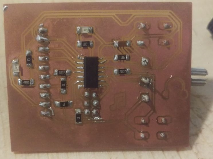
This was the final circuit created. I used eagle to create my PCB
I have used through hole components because my potentiometer was throughhole and I wanted all the control elements on one side. which is why i used through hole buttons and headers for the ISP. I have added other headers as well for all the remaining unused pins on the microcontroller to use for other puroses if i wanted. The idea to do so and create a "kind of" arduino board came from my colleague Hassan That created a multipurpose board to use for different purposes every time.
you may notice from the design that im not using two potentiometers and that is becuase I decided to used another input instead to replace that.

I found the footprint for the through hole 6 mm buttons in the "sparkfun switches" eagle library which you can find here
and the ten pin header in a library called pinhead which you can find here
however, despite finding libraries for my components, the packages were not exactly how I wanted them. with through hole components, a large drill size compared to the pad diameter could result in the pad coming off when producing the PCB. I have had an issue with that before, and the results are not pretty
you can see how I fixed a pad that came off here
So I had to adjust the package to avoid any problems.
Changing drill size for through hole components
There are different ways to do this. An easy and quick method if you are using fab modules and outputing your board as a PNG image is to just edit it in gimp and make the holes slightly bigger using a black paint brush to make the drill holes bigger or erasing it and replacing it with a smaller one as you see fit. This is prone to error though becuase you may make the holes too big or too small. Too big of a hole may rip the pad out or be even bigger than the pad which will give you no connection, too small of a hole means the components wont even fit through or even that fab modules wont detect it and drill it in the first place.
the second method ( the right method to elemenate errors and get the exact results you expect ) is to edit the package (the footprint) of the device you are using in eagle.
To do this the first thing you need to do is locate the component you want to change the drill size for in the pcb board you created. Doing this after creating the board should be okay and wont generate any problems. What WOULD potentioally generate errors is changing the pad size as making it bigger could mean that there wont be enough clearance between the pad and any tracks that are passing near it. I reccoment changing pad sizes BEFORE you rout. changing drill hole size is not a problem though as it will remain contained within the pad.
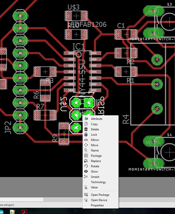
right click the device you want to change and select open package
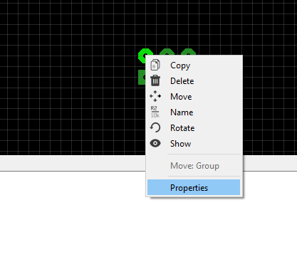
right click the middle of a pad and select properties
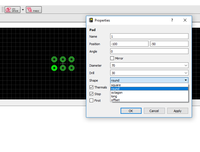
change the diameter and drill sizes to whatever values work for you. The values here are in mil. If you are using fab modules then you are probably milling with a 1/32 inch drill bit, which equals 31.25 mil. so that is the minimum hole value fab modules will be able to detect. change it to anything of that value or greater.
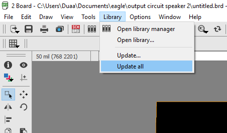
save and exit the package editor. select library then update all in the pcb board window. and that will change your footprint accordingly.
circuit Production
Milling the circuit
I used fab modules to mill my circuit. I exported the design into a monochrome PNG image from eagle and used that. The fun part about using a png image is that I could open it in GIMP and edit it to add patterns and shapes and as long as they are black on white, they will be milled.
This is my final circuit design that i milled ( download links at the bottom of this page)

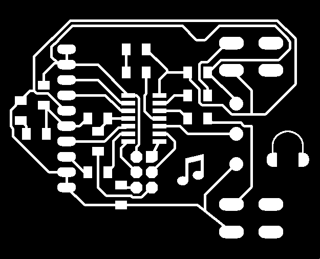

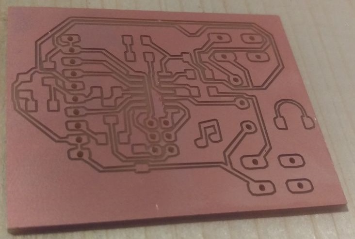


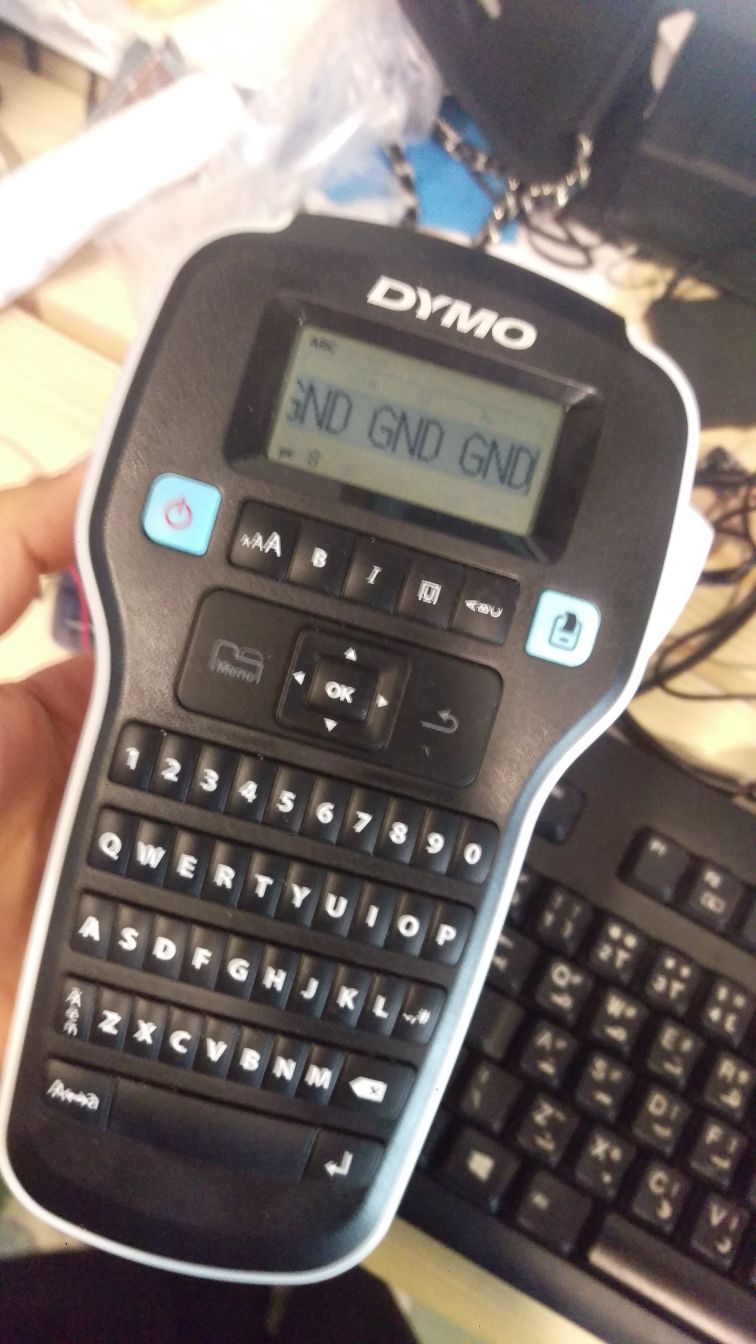

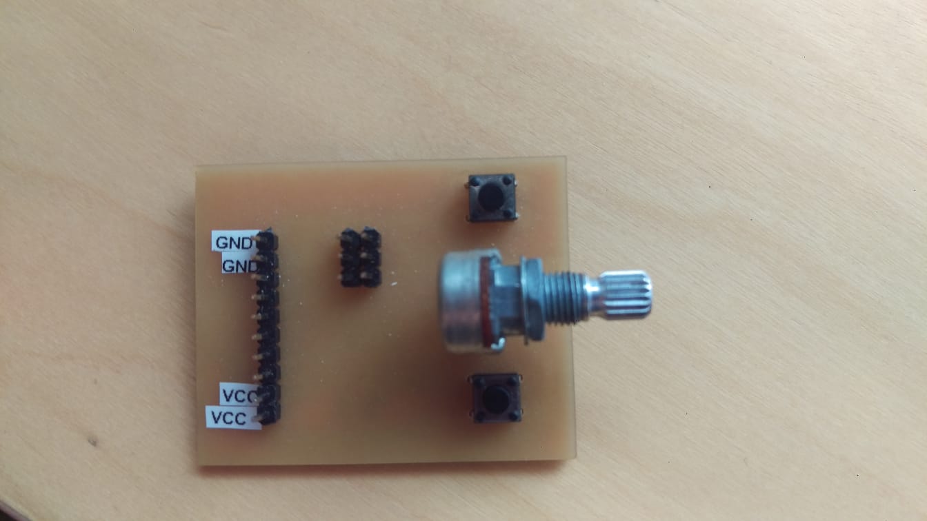
The circuit turned out really well. I used a label maker to mark my ground and VCC pins so I dont mix them up and cause an unfortunute accident ruining the circuit.
Programming
I started out with testing the circuit with a simple code using a button to light the LED to verify i am able to program the circuit and that it is operational before creating a more complex code.
note that in the circuit, the buttons are not connected to VCC, they are connected directly to the GPIO pins. The buttons use the internal pullup resistor of the Attiny, which means it has to be activated via code.
 const int buttonPin = PA0;     // the number of the pushbutton pin
const int ledPin =  PA2;      // the number of the LED pin


// variables will change:
int buttonState = 0;         // variable for reading the pushbutton status


void setup() {
// initialize the LED pin as an output:
pinMode(ledPin, OUTPUT);
// initialize the pushbutton pin as an input:
pinMode(buttonPin, INPUT);
digitalWrite(buttonPin, HIGH);  //internal pullup
}


void loop() {
// read the state of the pushbutton value:
buttonState = digitalRead(buttonPin);


// check if the pushbutton is pressed. If it is, the buttonState is HIGH:
if (buttonState == HIGH) {
// turn LED off:
digitalWrite(ledPin, LOW);
} else {
// turn LED on:
digitalWrite(ledPin, HIGH);
}
}
This simple code keeps the LED on until the button is pressed. I uploaded the code using my programmer and tested it out. It worked fine.
Now is the time to add an output device and use this circuit to its full potential. The idea behind the 8-bit mix tape is to use the buttons to toggle between cases of different styles of "mixing" and use the reading of the potentiometers using the analogread function to vary the output going to the speaker pin to generate music or beats. I am only using on potentiometer. I can add any other input device and use the value of that instead, or generate a random value in case i did not want to attach an input device. That is the point of the extra gpio pins i added to my circuit. I opted to generate a random number and use that instead.
 int speakerPin = PA7;
int buttonPin = PA0;
int potiPin3 = PA3;
//int potiPin4 = PB2;

int buttonState = 0;
int lastButtonState = 0;
int count = -1;
unsigned long int pulseWidthOFF = 0;
unsigned long int pulseWidthON = 0;
unsigned long int pulseWidthPart = 0;

unsigned long int newr;
unsigned char lobit;
unsigned char b31, b29, b25, b24;
int samplingDelay;
unsigned long int reg;
long t = 0;
int v = 0;
unsigned int c3 = 0;
int randNumber = 100;
unsigned int c4 = 4;
unsigned int analogValue;

void setup () {
//TCCR0A |= (1<TCCR0B = TCCR0B & 0b11111001; //no timer pre-scaler, fast PWM
pinMode (speakerPin, OUTPUT);
pinMode(buttonPin, INPUT);
digitalWrite(buttonPin, HIGH);
pinMode (potiPin3, INPUT);
// pinMode (potiPin4, INPUT);

reg = 0x551155aaL;
}
void loop () {
// read the state of the switch into a local variable:
buttonState = digitalRead(buttonPin);

if (buttonState != lastButtonState && buttonState == HIGH) {
// if the state has changed, increment the counter
count++;
t = 0;
delay(10000);
if (count > 9) {
count = 0;
}

}

lastButtonState = buttonState;
randNumber = random(0,1023); // generate a random number between 0 and 1023 to subsitute for one of the potentiometers.


//count = 2;
switch(count) {

case 0: // a classic
c4 = ((randNumber>>6) + 1);
c3 = (analogRead(potiPin3)>>0);
v = (t*(t>>8|t>>4))>>(t>>c4);
analogWrite (speakerPin, v);

delayMicroseconds(c3>>2);
t++;

break;

case 1: // ding dong

c4 = (((1023-randNumber)>>6) + 1);
c3 = (analogRead(potiPin3)>>0);
v = t * ((t>>15|t>>c4)&83&t>>(c4>>3));
analogWrite (speakerPin, v);

delayMicroseconds(c3<<2);
t++;
break;
case 2: // experimental 8 bit
c4 = ((randNumber>>6) + 1);
c3 = (analogRead(potiPin3)>>0);
v = t * ((t>>15|t>>c4)&83&t>>(c4>>3));
analogWrite (speakerPin, v);
delayMicroseconds(c3<<3);
t++;
break;
case 3:
c4 = ((randNumber>>2) + 1);
c3 = (analogRead(potiPin3)>>0);

b31 = (reg & (1L << 31)) >> 31;
b29 = (reg & (1L << 29)) >> 29;
b25 = (reg & (1L << 25)) >> 25;
b24 = (reg & (1L << 24)) >> 24;

lobit = b31 ^ b29 ^ b25 ^ b24;

newr = (reg << 1) | lobit;
reg = newr;
v = t * ((t>>c4|t>>reg)&7&t>>3);


//v = t * ((t>>4|t>>7)&c4&t>>(reg));
//v = t * ((t>>c4|t>>reg)&7&t>>3);


digitalWrite (speakerPin, v);
delayMicroseconds(c3>>0);
t++;


break;

case 4:

c4 = ((randNumber>>2) + 1);
c3 = (analogRead(potiPin3)>>0);


v = (t|3) * ((t>>1|t>>6)&c4&t>>3);


//v = t * ((t>>4|t>>7)&c4&t>>(reg));
//v = t * ((t>>c4|t>>reg)&7&t>>3);


analogWrite (speakerPin, v);
delayMicroseconds(c3>>0);
t++;


break;

case 5:

c4 = ((randNumber>>6) + 1);
c3 = analogRead(potiPin3);
v = t>>4&1?t>>5:-t>>c4 ;
analogWrite (speakerPin, v);
delayMicroseconds(c3>>1);
t++;


break;
case 6:
c4 = (((1023-randNumber)>>6) + 1);
c3 = (analogRead(potiPin3)>>0);
//v = (t|3) * ((t>>2|t>>83)&13&t>>c4);
v = (t|c4) * ((t>>c4|t>>11)&47&t>>3);

//v = t * ((t>>4|t>>7)&c4&t>>(reg));
//v = t * ((t>>c4|t>>reg)&7&t>>3);
//v = (1 & 17) * (t|83) * ((t>>c4|t>>17)&7&t>>3);


analogWrite (speakerPin, v);
delayMicroseconds(c3>>2);
t++;


break;

case 7:

c4 = (((1023-randNumber)>>8) + 1);
c3 = (analogRead(potiPin3)>>0);
//v = (t|3) * ((t>>2|t>>83)&13&t>>c4);
v = t * ((t>>c4|t>>3)&17&t>>9);

//v = t * ((t>>4|t>>7)&c4&t>>(reg));
//v = t * ((t>>c4|t>>reg)&7&t>>3);
//v = (1 & 17) * (t|83) * ((t>>c4|t>>17)&7&t>>3);


digitalWrite (speakerPin, v);
delayMicroseconds(c3>>2);
t++;


break;

case 8:

c4 = ((randNumber>>2)+1);
c3 = (analogRead(potiPin3)>>0);


v = t * ((t>>c4|t>>83)&7&t>>5);


digitalWrite (speakerPin, v);
delayMicroseconds(c3>>0);
t++;


break;
}
}
My output device is a transducer piezo buzzer (Part # AT1810TLW50R) . The "normal" piezo buzzers, as in the buzzers that come with an arduino kit you purchase, is typically an indicator piezo. That means that it comes with its own driving circuitry and you just need to supply it with DC voltage where it operates at a fixed frequency. A transducer piezo (the kind I used) would not functin with a DC voltage applied to it, it requires a square wave to operate and the frequency can be varied. The output i am sending it from the code is a PWM signal. I connected my buzzer directly to the output pin and started expeimenting.
note: It is good practice to connect the piezo or any output device to the pin through a resistor to limit current draw. I did not do that becuase i know that my piezo's max rated current is only 3 mA (according to the datasheet) and the ATtiny's GPIO pins current rating is 40mA so that is fine in this case. HOWEVER, if you are using anyoutput device that you are not sure of or using more than one output device at once it is not a good idea.
Measuring the power consumption of an output device
power consumption refers to the electrical energy per unit time supplied to operate an output device.. In home appliances it is measured in killowatts per houw (KWh) which means the amount of energy in Killowatts that a device consumes in one hour. This unit makes sense becuase large home appliances consume a lot of power, but when we are talking about small output devices that run on small voltages do not consume as much power.
Calculating power (P) is quite simple, It equals the current multplied by the voltage. I will be measuring the power consumption of a small DC motor.

Motors do not use the same current throughout their operation, it depends on many factors. Motors draw what is called "free current" which is the current drawn when the motor is rotating freely at maximum speed, under no load other than friction and back-emf forces in the motor itself. And they draw "Stall current" which is the current drawn when the motor is applying its maximum torque, either because it is being prevented from moving entirely or because it can no longer accelerate given the load it is under. The stall current is the maximum current drawn from a motor and is considerbly higher than free current. When motors change directions there is normally a spike in the current drawn as well.
For the purpose of this calculation of current consumption, we will assume the motor is running freely at all times and will use the free current.
Using a bench power supply, I supplied the motor with 3 Volts. The power supply showed that the motor was drawing around 0.250 A.
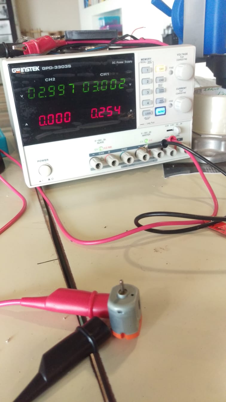
Thus our power is
P = V x I
3 x 0.25 = 0.75 Watts
If we wanted to run the motor continuesly for 1 hour it would consume 0.75 W = 0.00075KW. The power consumption of this motor is 0.00075KWh
Just a test. Notice the current change when I stop the motor rotation with my hand. It goes up to 2A!
The download links to all the design files and code
Design 2 Circuit eagle schematic
Design 2 Circuit eagle PCB board
Design 2 Circuit PNG tracks
Design 2 Circuit PNG outline and through holes