Input devices
This week's assignment is to Measure the analog levels and digital signals in an input device and to measure something by adding a sensor to a microcontroller board that I have designed and reading it.
group project : measure the analog levels and digital signals in an input device
For the group project we have to measure the signal levels for different input devices
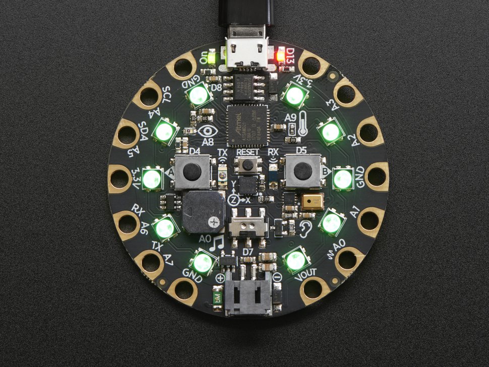
I have been working on the playground express board before during the embedded programming week and decided to test out some of the sensors (input devices) & also test out the serial plotter on the arduino IDE.
The playground express contains a light sensor, an accelerometer, a sound sensor, tempreture sensor and two buttons
I started first by selecting the board in the arduino IDE to be able to upload to it. I already added the playground express as a board in the arduino IDE

Accelerometer
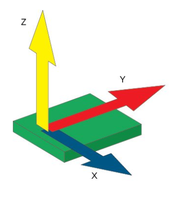
I started with the accelerometer becuase I find accelerometers to be very interesting. Accelerometers work by detecting the change in gravity (g) over the three axises (x,y and z). the accelerometer used on the board is the LIS3DH which is a three axis digital linear accelerometer.
I've used the following code to obtain readings of each axis:
#include < Adafruit_CircuitPlayground.h >


float X, Y, Z;


void setup() {

  Serial.begin(9600);

  CircuitPlayground.begin();

}


void loop() {

  X = CircuitPlayground.motionX();

  Y = CircuitPlayground.motionY();

  Z = CircuitPlayground.motionZ();


  Serial.print(X);

  Serial.print(",");

  Serial.print(Y);

  Serial.print(",");

  Serial.println(Z);


  delay(100);

}
CircuitPlayground.motion is a command to find the axis reading using a function in the circuit playground library.
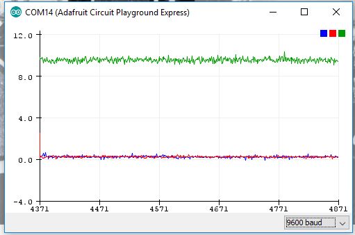
That was what i got when the board was flat. lets make sense of those numbers.

This paragraph from the LIS3DH datasheet shows that the X-axis and the Y-axis should measure 0g and the Z-axis should measure 1g when the accelerometer is horizontal, which is consistant with the results showing up on the serial plotter. But why is it showing the X and Y at around 10 ? That is is actually measuring 9.8 m/s2 which is earth's gravity. Going in the opposite direction (flipping the playground express upside down would result in negative Z values. this accelerometer is a digital sensor connected through SPI.
Measuring Analog data
In the next part of this page we will measure analog data of a sensor through the analog to digital convertor on an attiny. Here, we measured the analog value of a sensor using a multimeter.
A multimeter is an electronic measuring instrument that combines several measurement functions in one unit. A typical multimeter can measure voltage, current, and resistance and often more. The multimeter we have is a TMM 7201.
The analog input device we are measuing using the multimeter is a Low Voltage Temperature Sensor TMP36. You will find the datasheet for this sensor
here
As per the datasheet, we will find that it need to be powered by a voltage of (2.7 V to 5.5 V) and is calibrated directly in degrees celcius. Meaning the values we get with a simple conversion coorisponde to celcieus degree values.
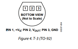
The first step is to connect the tempreture sensor to the supply voltage. The data sheet shows the correct way to connect. The data sheet also has a graph showing the voltage level at every tempreture.
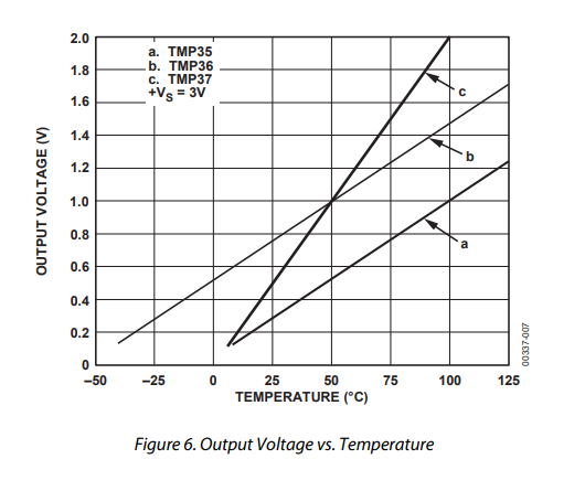
form this graph we can conclude that the tempreture in celcieus equals 100*(reading in V) - 50.
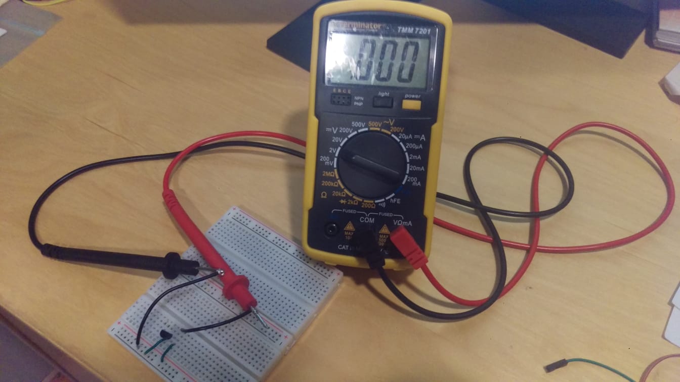
I powered on the tempreture sensor and connected the data pin to the multimeter. I set the multimeter to the 2 Volts DC setting as the voltage will not exceed that.
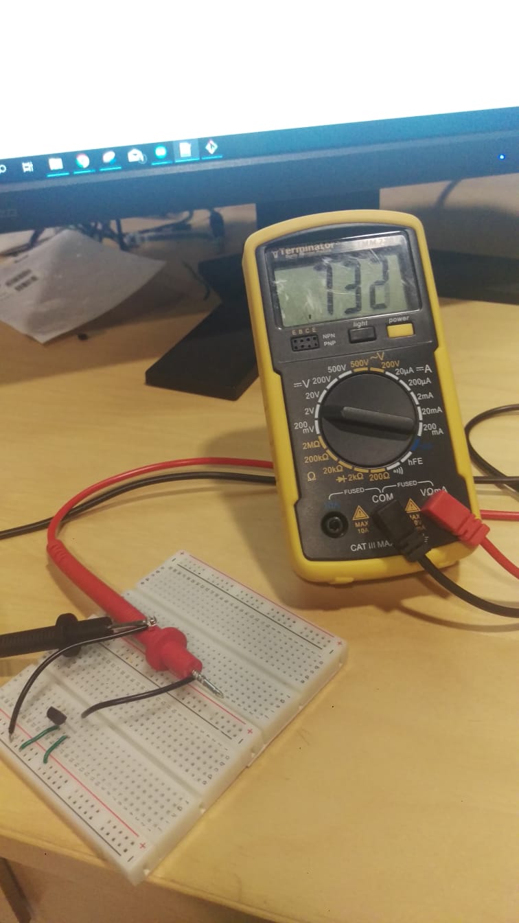
The voltage is 0.732V, lets calculate the tempreture.
Temp = (0.732 * 100 ) - 50 = 23.2 degrees celcius, which is around room tempreture so it makes sense.
I touched the tempreture sensor with my hand to add my body heat to it and mesured again
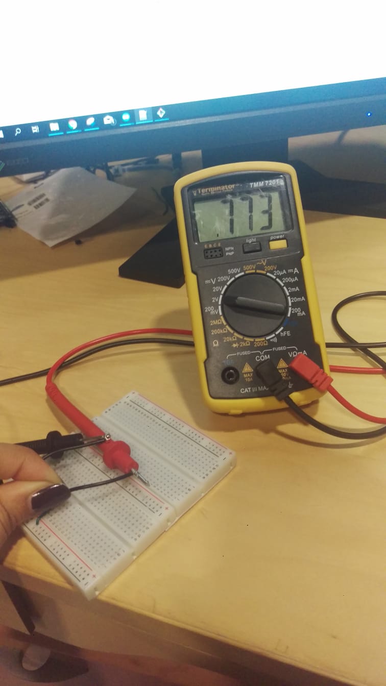
The voltage rose gradually until it stopped at 0.773 V, lets calculate the tempreture.
Temp = (0.773 * 100 ) - 50 = 27.3 degrees celcius
measuring something by adding a sensor to a microcontroller board that I have designed and reading it
the sensor I have chosen to add to circuit I designed previously is a greyscale analog sensor. The datasheet for the sensor can be found here . It is the JMP-BE-1111 analog grey scale sensor. It's a part of a robotics kit but I am using it here on its own connected to my circuit to measure different levels. I have used grey scale sensors before in creating robots normally for locating purposes, for example when it comes to following a line or something of that sort, a grey scale of a color sensor is very helpful.
The greyscale sensor works by shining a light at an object and then recording the intensity of the reflection (brightness). Wenb lookig at it you can see that there are two different parts, one that shines light and one that recieves the reflection.

The sensor recieves 5Volts as per the data sheet and outputs an analog voltage on its data pin according to the color of the material places infromnt of it.
I created a small code to read the analog data recieved through the analog to digital converter in the board and reading them through the serial monitor
#include < SoftwareSerial.h >
#define RX PA1
#define TX PA0
#define sensePin PA6
SoftwareSerial mySerial(RX, TX);
int sensorInput;    //The variable we will use to store the sensor input
void setup() {

mySerial.begin(9600);
pinMode (sensePin, INPUT);
}
void loop() {
// put your main code here, to run repeatedly:
sensorInput = analogRead(sensePin);    //read the analog sensor and store it
mySerial.print(" Raw reading:");
mySerial.print(sensorInput);
delay(100);
}
I uploaded the code to my board and hooked up the sensor and started recieving data. The board is connected to my pc via a 5volts ftdi cable which is also powering the board
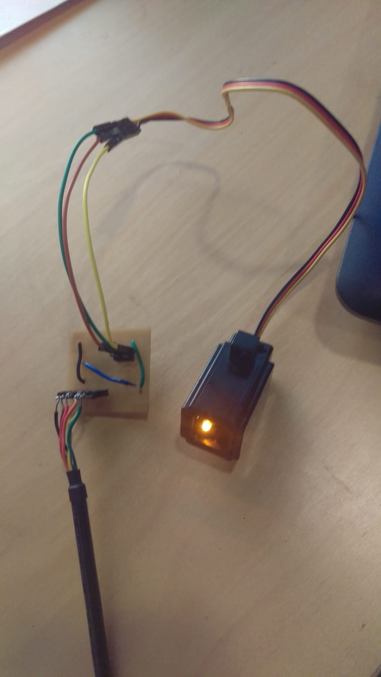
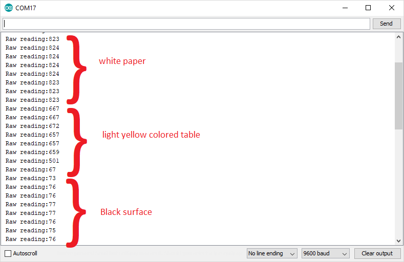
Normally, for robotic uses anyway, the greyscale sensor is used to distingish between black and white. I adjusted the code based on the data I found to light the led when the greyscale sensor is pointed at a black surface. (which yeilds a very low voltage according to the results we observed.
Conducting this "calibrating" test is a good idea to observe the differences between the data given as it depends on the lightning of the room as well a lot of the time. I used 150 as my cuttoff point to detect black
#define sensePin PA6
int sensorInput;    //The variable we will use to store the sensor input
int ledPin = PA3;
void setup() {
pinMode (sensePin, INPUT);
}
void loop() {

sensorInput = analogRead(sensePin);    //read the analog sensor and store it
if (sensorInput < 150) {
digitalWrite(ledPin, HIGH); }
else
{
digitalWrite(ledPin, LOW);  }
}
Input circuit design and fabrication
For the input circuit design and fabrication, this is a mutal circuit between this week and the output week. I designed a circuit that contains three permanent input devices (two push buttons and one potentiometer). we have covered push buttons betore and they are quite straight forward (digital device on or off only), so I will focus my attention on the potentiometer.

I have on 10k ohm potentiometer. A potentiometer is a three-terminal resistor with a sliding or rotating contact that forms an adjustable voltage divider.It is a a variable resistor with a third adjustable terminal. The potential at the third terminal can be adjusted to give any fraction of the potential across the ends of the resistor. It is great for a lot of applications in which users input is nesessery to adjust a spicific value, for example volume.
I connected the potentiometer to one of the pins in which I can read its value through the analog to digital converter, thus givinbg me a value of 0 to 1023. Full schematic below.

For more information on the fabirication process and board design and the code that combines input and output devices of this circuit, it is all posted on this page here