Week 7: Electronics design
This weeks assignment is to:
- redraw the echo hello-world board
- add (at least) a button and LED (with current-limiting resistor)
- check the design rules, make it, and test it
Designing a board with Eagle
I tried to download Eagle but for some reason it didn't work. Therefor I used Emma's laptop to work with Eagle. But at the moment I'm writing this documentation I have a new laptop and installed Eagle succesfully.
Adding libraries
When you first install Eagle, you might have to install libraries of components you want to use. This is done in the library folder on your computer that is created when you install EAGLE. We got two libraries over the mail from Emma, called fab.lbr and ng.lbr ng standing for Neil Gershenfeld. We also neede a library called supply1, which contains GND and VCC. I checked at Emma's laptop if the right libraries where there. They where. I have now installed them on my own laptop by simply adding them to the folder C:\EAGLE 8.7.0\lbr
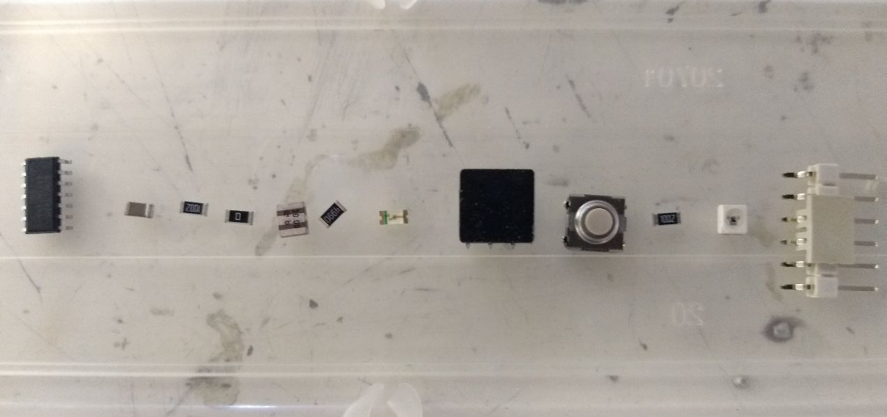
The components
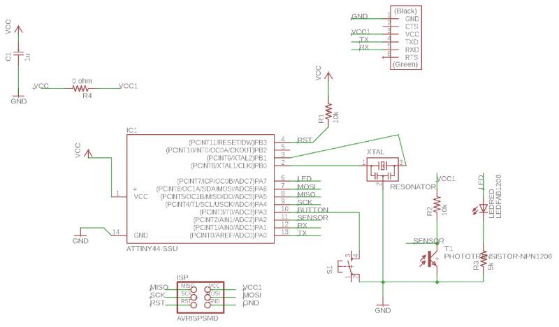
Emma gave us a schematic on paper with all the right components and connections. The assignments says to at least add a button and LED to the hello-world board.
- 6-pin header
- Microcontroller ATtiny44A
- FTDI header
- 20MHz resonator
- 2x Resistor (10k)
- Resistor (value to calculate for the LED)
- Button (6mm switch)
- LED (red)
- Phototransistor
- Capacitor (1uF)
- Ground
- VCC
Eagle commands
These are the commands I used for adding, connecting and naming the components.
- Add = to add a new object from the library
- Move = move objects
- Delete = delete objects
- Net = make a wire for a connection
- Label = label the object. This makes the name visible in the schematic.
- Name = name the objects and nets. You can connect an object whithout drawing the wires by naming the net. If you give two nets the same name, Eagle will ask if you want to connect.
- Value = add a value to the object

Switching to lay out view
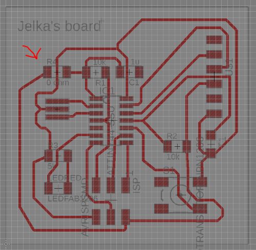
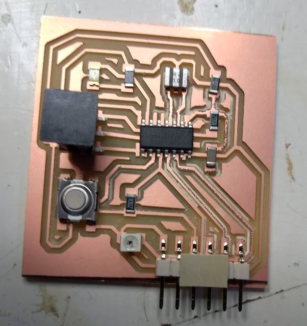
When you have added and connected all the components, you should run an ERC: Electronic Rule check. I didn't do this in this week, but did do this in the weeks of input and output devices. You can find it as the first option in the toolbar, under Tools. Eagle will tell you if your schematic is consistant and if you gave all your components a value and the like. When all is OK, it is time to make a lay out for your board. You can switch to lay out view with the icon  that is on the top left in your toolbar. Eagle will throw all the components in left corner of what could be your board. MAKE SURE YOU KEEP YOUR BOARD ON THE POSITIVE SIDE OF YOUR ORIGIN. This is upper right of the origin. Eagle gives you complaints and strange functionallity if you don't. Now I placed all my components on the board with the 'move' function.
Autorouter
Eagle has an autorouting function. It never gave me 100% of the connections. The rest of traces you have to do yourself.
Manual routing
To make a trace you use the command 'route'. Eagle gives you a few sorts of traces, you can scroll by right clicking the mouse until you are happy with the kind of trace. Electricity doesn't like straight corners, so I used the trace with the 45 degrees angles as much as possible. Two very helpfull commands are 'ratsnest' that unwinds your spaghetti of nets and 'ripup' to change traces into nets again. This proces of tracing has cost me 8 hours of work. It was frustrating and addictive at the same time. What helped me was to make pictures when I had to move components. The traces don't really follow your component when you move it. I got really confused and the pictures helped me to fix the traces again. At last I had to use a 0 ohm resistor as a bridge to be able to place the last trace.
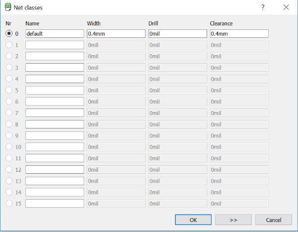

Net classes
I used only one type of net class and named it default. As I am going to use a 0.4 mm end mill, this is the minimum value I set for width and clearance.
DRC
DRC stands for Design Rules Check. It checks if your traces and pads (the locations where your components touch the board) have enough clearance. If you set the clearance you want and click 'apply' Eagle will show you where you have made mistakes so you can improve your board. I did this three or four times untill Eagle gave no errors anymore. The are the Design Rules I set:
Clearance:
- Wire-wire: 0.4mm
- Wire-pad: 0.4mm
- Pad-pad: 0.4mm
I did not use Via because I only have only one layer on my board.
Distance:
- Copper/Dimension: 0.4mm
Sizes:
Exporting to PNG
When you have finished your board's lay out and DRC gives no errors anymore, you are ready to export the file to PNG, the file type that can be used in the small milling machine. For this you need the traces that need to be engraved and the board's outline that has to be cut. Click the layers icon  in the left toolbar. You can define as much as 255 layers in your board lay out. For the hello_echo board traces you need Top Layer. Select only this layer to be visible and click OK. Then click File-Export-Image. Choose a name for your file and choose monochrome. I set the resolution to 600 dpi. I made the Top Layer and dimensions visible in the layer setings. Also I used a layer bdocu, layer 52. Then I set the grid to 1mm and drew a rectangle around the layer Dimension with an offset of 1mm. This layer I exported as PNG. I opened it in GIMP, where I drew the offset of 1 mm inbound of the square and inverted the image. Now my files for engraving and cutting where ready. Down here is a zip file with my Eagle files and cutting/engraving PNG files
Eagle and PNG files Hello_Echo
Engraving and cutting
For the procedure off engraving and cutting the board, I did the same things as in week 5 But this time I had to first attach a sacrificial layer. I did as I remembered Emma told us; clean the the layer with sticker solver and then added new sticky tape in straight, non overlapping lines, but obviously I did something wrong, because half way the engraving, the end mill plunged really deep in my board. It turned out that the sticky tape had gone all messy. Probably the sticker solver hadn't evaporated yet at the moment I put on the new sticky tape. Another lesson learned.
Soldering
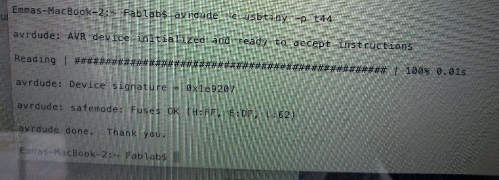
Testing the board
There wil be no programming yet this week. We only need to check if the computer can see the hello_echo board. For this I connected the programmer I made in week 5 to my hello_echo board. I was carefull to connect it in the right oriëntation. I plugged the programmer to a USB port in Emma's laptop and opened a terminal. In the terminal I typed: avrdude -c usbtiny -p t44 And then the AVR dude told me he could see the board.