

Week 02 - Computer-Aided Design
CAD! Here I talk about the process I followed of my very first Fabacademy’s model.
Note: All the files here
Contents
- Contents
- Software trial
- Part modelling with SolidWorks
- Explorations with Blender
- Explorations with Rhino
- 2D Software - Explorations with Inkscape
Software trial
I have some brief experience working with SolidWorks and CATIA V5 during my university degree and since SolidWorks is available for Educational purposes within the FabAcademy course, I will stick to this option for main modelling purposes. However, below I post other trials with Blender and Rhino, as a first approach to both softwares at the end of this week’s assignment.
Furthermore, one of the ideas of my final project](/2018/labs/barcelona/students/oscar-gonzalezfernandez/finalproject.html), would be to create a model of a person in blender whose motion can be controlled from an external input of acceleration, from the sensor itself on the person’s body. However, since I am not there yet, I will try to cover my first steps with the tool in this assignment and explore further during the course.
Part modelling with SolidWorks
Scope
The idea would be to create a 3D model of a gas-testing system for sensor experimentation, within the SmartCitizen framework. This system would be intended for indoor/outdoor gas analyser characterisation that involve low-mid cost gas sensors. It will be part of a broader task related to sensor characterisation and a deeper analysis of the gas measurements. An image of the type of mid-cost sensors used in the testing is depicted below:
 Image Credit: Alphasense
I detail below some guidelines for the design, in order to have some guidance for the purpose of testing gas analysis:
- It should be able to accomodate several sensors from SmartCitizen SGX MiCS 4514 and alpha-Sense in a flexible way (any amount of sensors)
- Outdoor testing in urban environment
- Accomodate a fan able to stir the gas in a homogeneus way
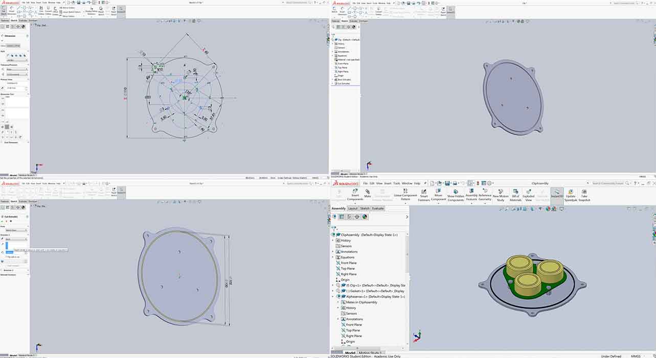
The sensors to test within the device have three main bodies (in yellow below), mounted on a PCB (in green). The idea would be for them to be in the chamber completely and for that a clip is designed and included below. This clip is designed with a simple extruded profile and then removed some material for the holes and the joint:
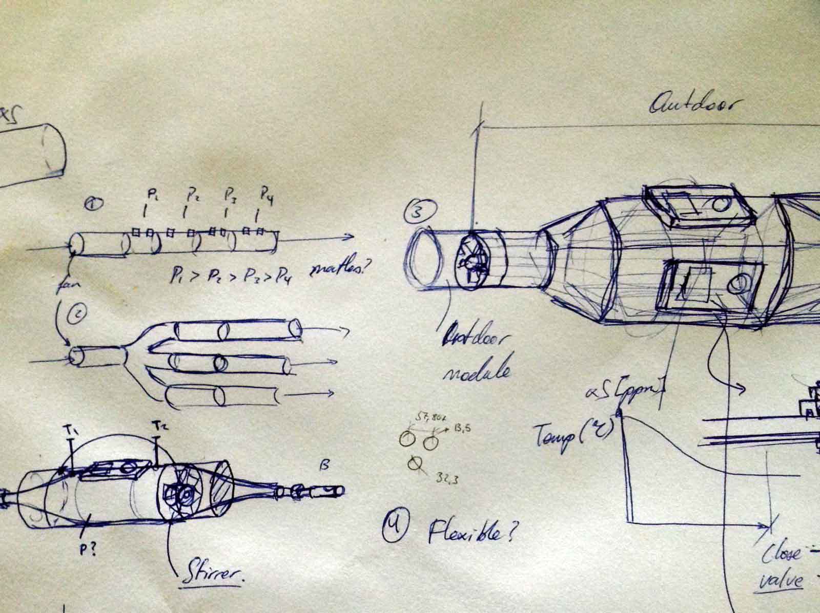
Initial Paper Sketch
Some first iterations of this system are depicted below:
Model
The proposal is to create a modular system that would look like the following:
Below I will detail some points about how the operations are done. The whole device is an assembly of: the main body, a fan and it’s casing, some joints and finally, the clip with the sensors mounted, shown above.
The main body is done with a loft/base pattern, extended from an input circle, through two rectangles and finally into an output circle, all parametrised. These are separate sketches contained in different reference geometry>plane. In order to create the reference geometry, I also defined an edge at which I would also include some parameters from an external file:

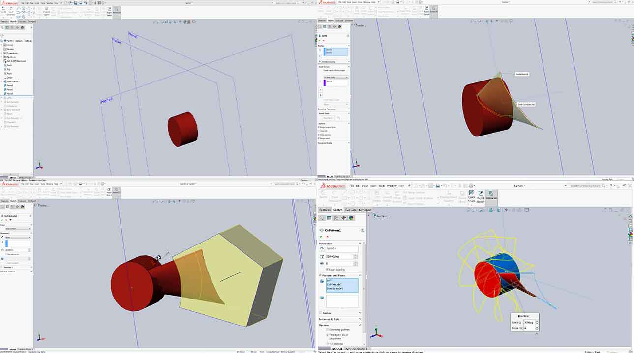
The fan, is created based on a interesting tutorial. The process followed is:
- Create a cylinder (by extrusion or revolve)
- Create the base profile of the fins by a lofted profile in two planes (same as the main body)
- Use a circular pattern to have more fins
- Cut them with a extruded cut in order to have a more realistic outline
Finally, I have tried to explore further about this type of parametric design. This is done by linking externally all the files with a constants file such as:
"inlet_diameter"= 30
"total_length"=200
"outlet_length"=80
"outlet_diameter"= 50
"side_length"=115
"inlet_lentgh"=80
"flat_length"=120
"side_height"=55
And then link it from SolidWorks in order to use them for the model:

Explorations with Blender
Blender is a total different program of what I am used to do. From Blender’s website, we can find a description of the capabilities of it:
Blender is an open-source free 3D creation suite. It supports the entirety of the 3D pipeline—modeling, rigging, animation, simulation, rendering, compositing and motion tracking, even video editing and game creation.
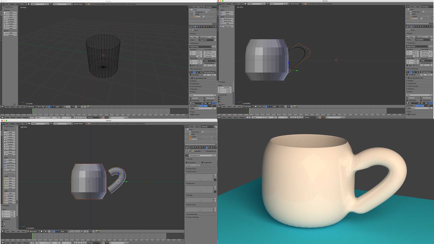
What is interesting for me in Blender, is that you can use a Python API to program in your models. Since I am not there yet with the program, I will have a look through it with a tutorial to get started. For this, I created a cup through following this Youtube tutorial and have posted some captures of the process, as well as the final render below.
For now, what I know about Blender, is that it manages a totally different environment for 3D modelling compared to SolidWorks or Catia. At this point, one has to change from the concept of modelling bodies, parts and making assemblies, to surfaces, vertices and edges, by manipulating, with more or less artistic skills, the entities within the model.
The cup below is done following the process:
- Create a cylinder from Create>Cylinder
- Change to wireframe view in Edit mode and delete the top side center vertex
- Deform the shape of the cup by selecting nodes (Press B to create a box) and scaling them (Press S)
- Extrude the top pixels (Press E) and create the inside geometry. Repeat over until the inner part is finished
- Create the handle of the cup by extruding a circle (Create>Circle) over a path (Create>Path)
- Join them and create the inner faces
- Create a surface modifier to subdivide the entities
- Add material to both the bottom plane (Diffused) and the cup (Mix Shader > Diffused BSDF/ Glossy BSDF)
- Create a camera and orient it
- Create a plane with a material that Emmits light (Material>Emission> Value = 10)
- Create the render and explore the different elements: samples (number of divisions), clamp (closer to 1.00 in order to eliminate fireflies)
Explorations with Rhino
Finally, I have done some explorations with yet another design software called Rhinoceros. Rhino is a 3D modelling sofware based in NURBS (non-uniform rational B-splines), which are a mathematical model used to represent curves and surfaces. Since Rhino is not a parametric software as, for example, SolidWorks or Catia, the concept is somehow similar to that found in Blender, however, Rhino gives us the possibility to create a parametric model with the help of Grasshopper, a visual programming environment.
To get introduced to the combo Rhino+Grasshopper, I found this interesting introduction to them. I detail some of the concept I learnt from this tutorial and my very basic understanding of them below:
- Create a basic geometry like a curve in Grasshopper: 3 circles by ** Set multiple curve**
- Loft/base pattern
- Divide the surface of the generated surface
- Parametrise it with numeric sliders
- Understand what is behind the scenes by the help of a panel. The panel shows the entity and it’s related to the connectors in the grasshopper’s interface. The type of connector will be determined by the entity of what it points to.
- Create another instance of the object and move it with a slider

2D Software - Explorations with Inkscape
For the 2D software, I did some initial tutorials with Inkscape. It is a vector graphics editor, free and open source, and I will be using it for editing vector graphics throughout the course, such as the materials for the electronics boards cutouts and so on.
In order to get started, I followed this tutorial and know the very basics of the program. Then I moved forward and created a logo with this other tutorial in order to create a logo.
For this, the process goes as follows:
- Start by creating the pencils and edit their forms using the basic rectangle commands. Use the following shortcuts to modify items:
- Hold Shift while selecting a colour to apply that to the stroke, instead of to the fill of an object
- Hold Ctrl to move something restraining an axis
- Hold Shift+Ctrl to rescale something maintaining proportions
- Click again on an object in Select mode to activate the rotation or scale functions
- Use the Ctrl tool on a node to move it
- Create the flags and the rectangles with simple shapes as the pencils and add a polygon in stars shape at the bottom
- Finally, create the nice looking text by:
- Creating a circle
- Creating the text
- Select the text and the circle (Shift + Click) and go to Text > Put on path
- Finally, add letter spacing by double clicking the text and make it look evenly distributed
With this tutorial, I found that Inkscape has much more potential than I initially thought it did, because at least on MAC, it runs on XQuartz and some of it’s functionality feels a bit flimsy at the beginning. Although, after doing this easy but nice logo, it is a tool worth considering for vector graphics in the future: