4 Axis CNC Hot Wire Foam Cutting Machine
Mechanical Design
1 Initial concept.
2 Mechanical Design Concept.
3 Material list.
4 Assembling the machine.
5 Conclusions, What would I change?
1 Initial concept

Replicable-Parametric.
Use structure as linear guides
Control the tension mechanically
I have divided this project into systems, which we can apply to the mechanical design, to the electronics and to the interface
The development of the system that I liked the most has beens the cable tensor system, since there is ingenuity in solving a problem in a simple way besides making a board for input and ouput.
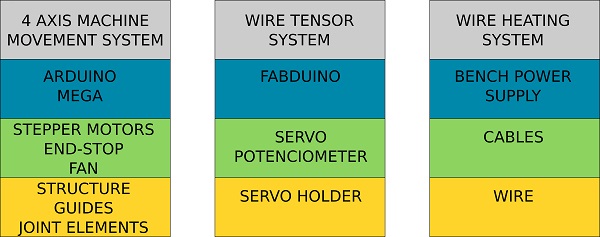
2 Mechanical Design Concept
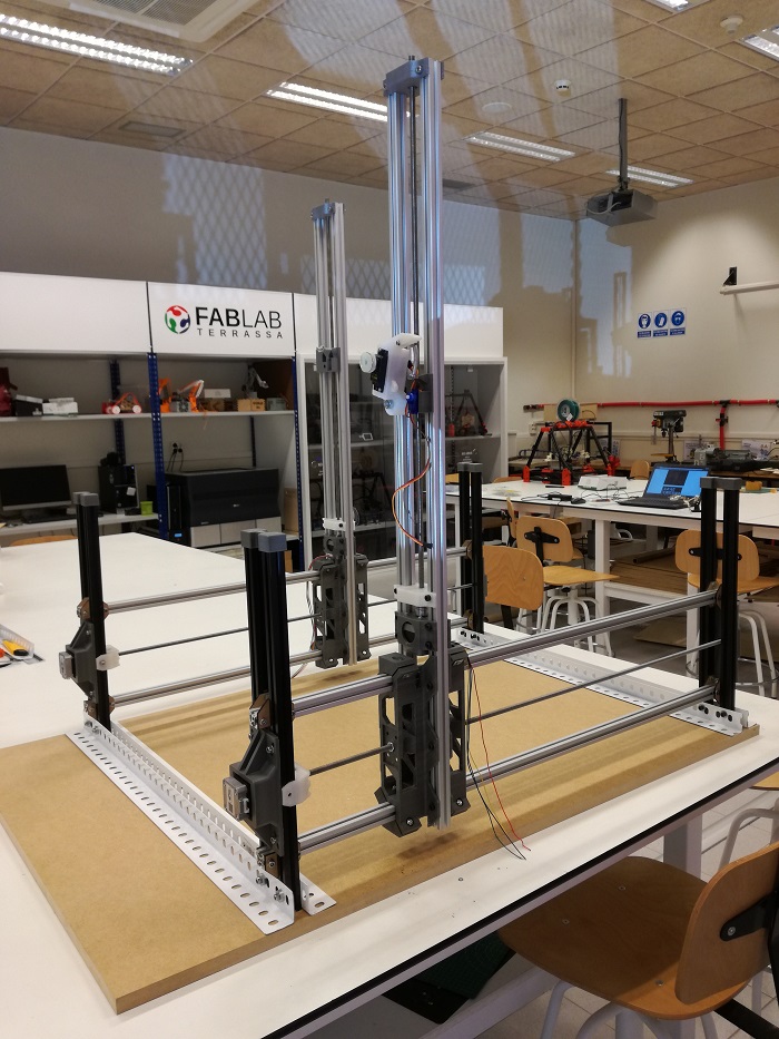
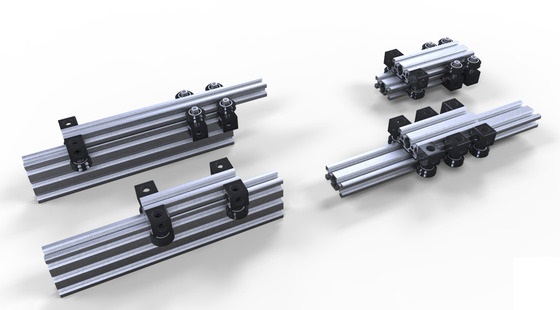
4 axis machine movement system
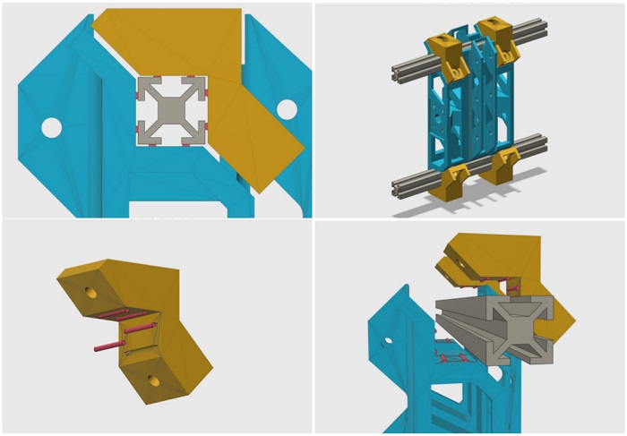
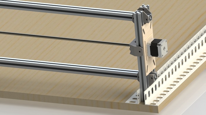
One of the concepts to emphasize in the design of the machine in the use of the structure as a linear guide. The cars will move on the same structure using as element antifriction small segment of tribo filament. This filament is up to 50 times more abrasion-resistant than standard 3D print materials.
Here you can see the.Tribo filament data sheet.
The design of the machine allows it to widen the size of the machine.
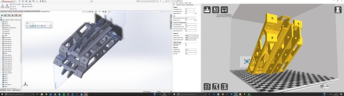
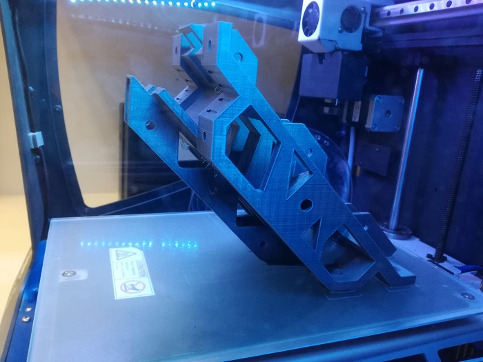
Some structural parts are 3D printed.
Wire tensor system
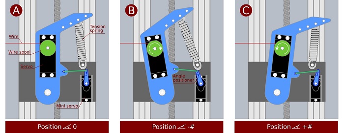
Another important design solution has been the system to maintain the tension of the hot wire. In addition to using a tension spring, a servo motor is used to wind or unwind the hot wire spool and another servo to define the correct position of the tensioning arm. To the first servo we remove the potentiometer so that it only works as a motor without feedback and the other servo we remove the engine so that its only function is to send a feddback.
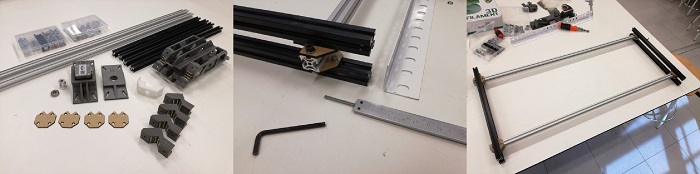
3 Material List
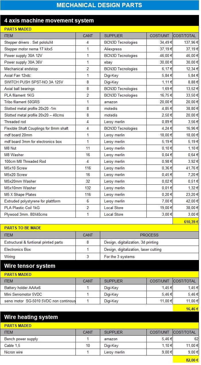
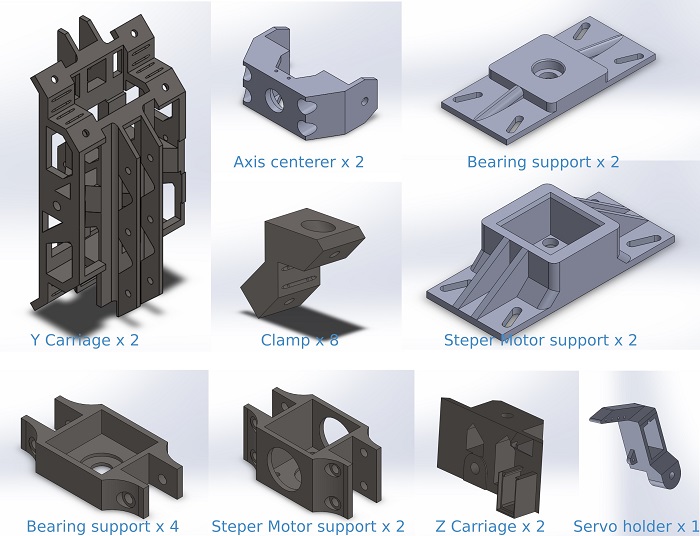
All printed with PLA, infill 50%, layer high 0,2
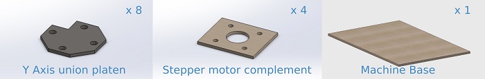
I use MDF for those elemnets to avoid flexion of the material
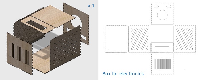
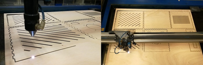
I have designed a box to hide the electronics and host a future lcd screen,I use 3mm Plywood board. Easy to cut and nice look
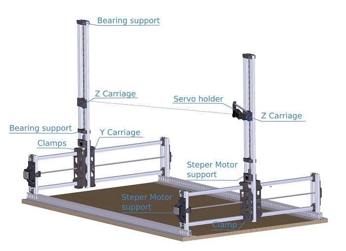
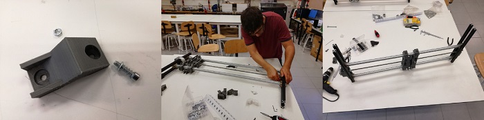
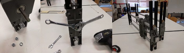
4 Assembling the machine
4 axis machine movement system
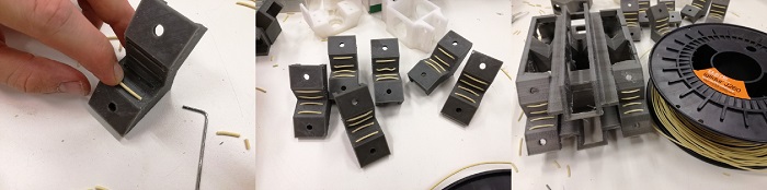
The design of the clamps and carriage has a small guides to introduce small segments of tribo filament . This filament is very brittle so introducing it can be a bit tricky, you just have to find the right size and a little bit of skill
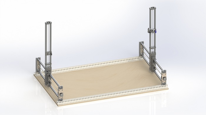
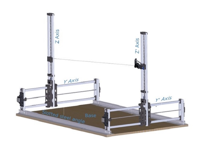
Assembling the Y-axis. Using the wooden plate, we join the vertical and horizontal metal profiles that will make the Y-axis. At one end we must leave space to be able to screw the slotted steel angle. As a result we obtain a rectangular figure in which there is a lower part and an upper one. The bottom screws should be tight and the upper screws should not.
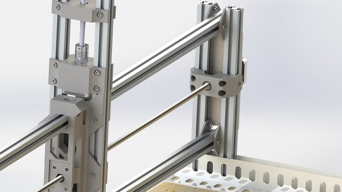
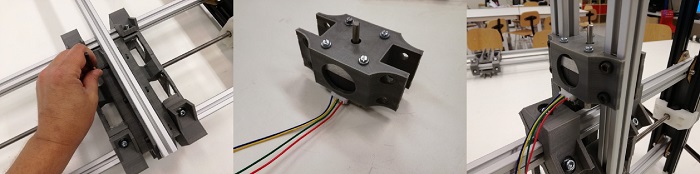
When assembling the carriage of axis Y we set-up the distances between the horizontal metallic profiles. We must insert the Threaded rod, the Stepper motor support and the bearing support. To assemble the carriage we use the clamps, the ones are attached to the carriage with screw and nut with a spring in the middle. Do not over tighten.
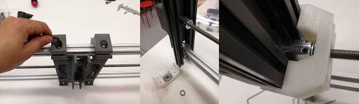
Now we assemble the axis centerer. We place the coupling on the shaft of the stepper motor (again, do not overtighten) and a washer between the coupling and the bearing. The bearing is housed inside axis centererin, this also must be bolted without being overtighten by the exterior hollows.
Now adjust the Y axis by moving the carriage from one side to the other (better if you use an electric screwdriver), now we can tighten all the screws.
To finalize with the Y axis we place a washer that will be in contact with the ball bearing and then 2 nuts which we will tighten between them.
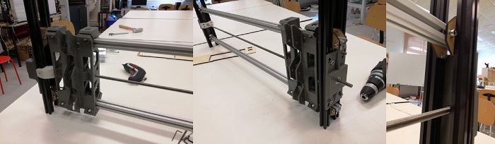
Now we begin to assemble the Z axis. We place the metal profiles all at the same height and tighten the screws well, place the motor stepper bracket and tighten the screws.
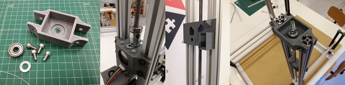
Before adding the threaded rod we rub on it the carriage of the Z axis, then we add the threaded rod using the coupling to attach it to the shaft of the motor stepper, the coupling must be slightly separated from the motor stepper and separated from the ball bearing by a washer. Then we close with the bearing support. . Finish the structure of the Z axis by placing the bearing support of the end, this is placed in reverse and tighten with washer and double nut.
Wire tensor system
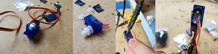
It is time to prepare the tensioning system of the hot wire. As I explained before we will use 2 servos. Here, preparing the servo that will do the work of obtaining the feedback of the tension of the hot wire. Disassemble everything related to the motor and stay with the potentiometer, eliminate the welding to then weld the cable that is left of the motor.
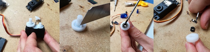
Prepare the second servo, this will do the motor function and will use the servo feedback that we have already prepared. I have not got servos of continuous rotation so I will have to modify it. Breaking a small flange and extracting a small piece of plastic that blocks the movement of the engine.
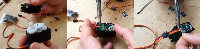
Reassemble the servo and open it at the back to eliminate the welding of the potentiometer so we can weld the cables of the potentiometer of the first servo. The potentiometer of this servo is left inside but deconected.
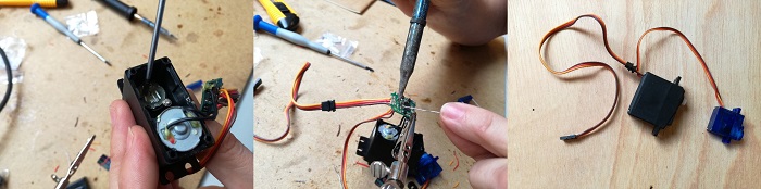
Once we have soldered the cables we must make a small hole in the back cover of the servo to allow the pass of the cables.
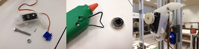
We insert the servos in their respective spaces. Now is when we start doing improvised things. the servomotors come with coupling pieces, we will use the round piece and we stick it to the thread reel.
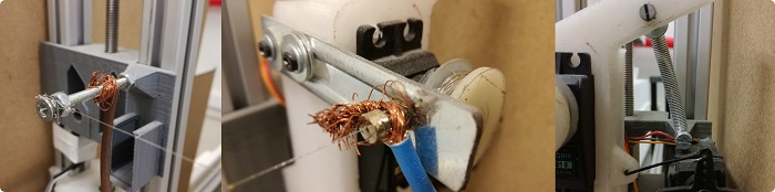
Another improvise work! A screw to hold the hot wire and connect one of the electric wires, a piece of metal to make an element that guides the hot wire so that it always comes out of the same point, a rigid cable bent to transmit the movement.
Finished assembly.
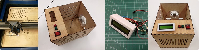
I made a box to house the electronics and put a lcd screen and a couple of buttons, the functionality of these elements are not included in this final project, for now it is a ventilated box for electronics..
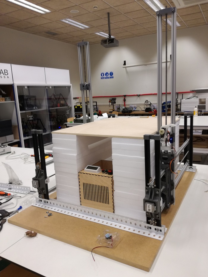
I cut a few pieces of fosmboard and stacked them until they reach the useful cutting height and cut a board to have a smooth and stable surface.
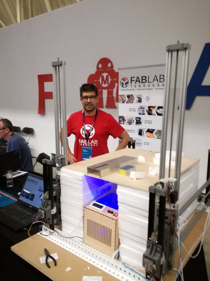
Here I am presenting the machine at the Barcelona makerfaire 2017.
5 Conclusions, What would I change?
Some plastic parts can be redesigned to make them stronger and more robust so that they can resist the tightening of screws without fear of breaking
The conclusions about the mechanical design I have meditated on after operating the machine.
I recently assembled a cnc milling machine that used the vslot system, it has made me very practical and functional and the price of its components is relatively low. I liked to try new things but if I did this machine again I would use metal profiles vslot to improve the movement of the carriages.
Threaded rod or Timing Belt, The threaded rod has its own music, to be more precise they are a bit noisy. I would also change to Timing Belt, I do not think it will lose precision and in case of wear it is not difficult to make a change
Solidworks design files are too big to be in fab academy git, you will find them in my personal git, other wise the stl files are available in the fab academy git
Background
Machine
Electronics
Interface

This work is licensed under a Creative Commons Attribution-NonComercial ShareAlike 3.0 Unported. International License.