week 8 - embedded programming
-individual assignment: read a microcontroller data sheet
program your board to do something, with as many different programming languages and programming environments as possible
-group assignment: compare the performance and development workflows for other architectures
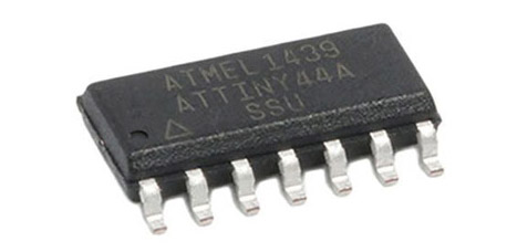
This week we will learn how to program our boards using Arduino software. We will work a lot with ATtiny microcontrollers, which are small, cheap ($2-3) microcontrollers that are convenient for running simple programs.
The ATtiny45 and ATtiny85 have eight legs and are almost identical, except that the ATtiny85 has twice the memory of the ATtiny45 and can therefore hold more complex programs. The ATtiny44 and ATtiny84 have 14-legs and more inputs and outputs. The ATtiny45 or 85 is a great option for running simple Arduino programs: it's small, cheap and relatively easy to use. It does, however, have some limitations relative to the ATmega328P on an Arduino Uno:
- There are fewer pins, meaning you can't connect as many components.
- There's less flash memory (4KB or 8KB instead of 32KB), meaning your programs can't be as big.
- There's less RAM (256 or 512 bytes instead of 2KB), meaning you can't store as much data.
- There's no hardware serial port or I2C port (Wire library), making communication trickier. (There are workarounds, like the SoftwareSerial library or the TinyWire library, but they're not as robust and flexible.)
Reading this datasheet will be helpful to know more about them, even though it's a bit of a heavy language for someone who doesn't know anything about electronics.
The ATTiny44 is high Performance, low Power 8-bit Microcontroller with advanced RISC architecture. These are its general features:
- 4K Bytes of Flash Program Memory
- 256 Bytes of Programmable EEPROM
- 256 bytes SRAM
- 12 general purpose I/O lines
- 32 general purpose working registers and 8-channel 10-bit ADC.
- Internal calibrated oscillator
- Operating voltage supply between 1.8 ~ 5.5V.
There are two kinds of ports:
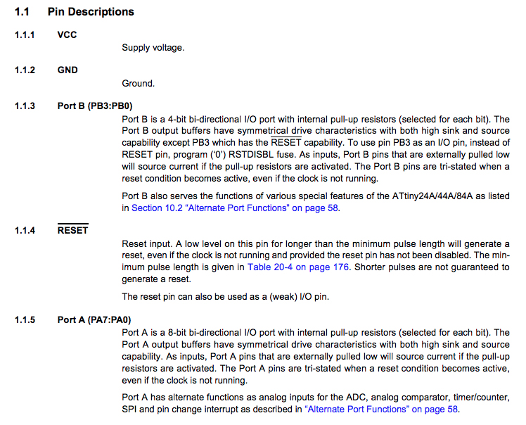
- Port A pins are 8-bit bi-directional I/O port with internal pull-up resistors (pin names are from PA0 to PA7)
- Port B pins are 4-bit bi-directional I/O port with internal pull-up resistors (pin names are from PB0 to PB3).
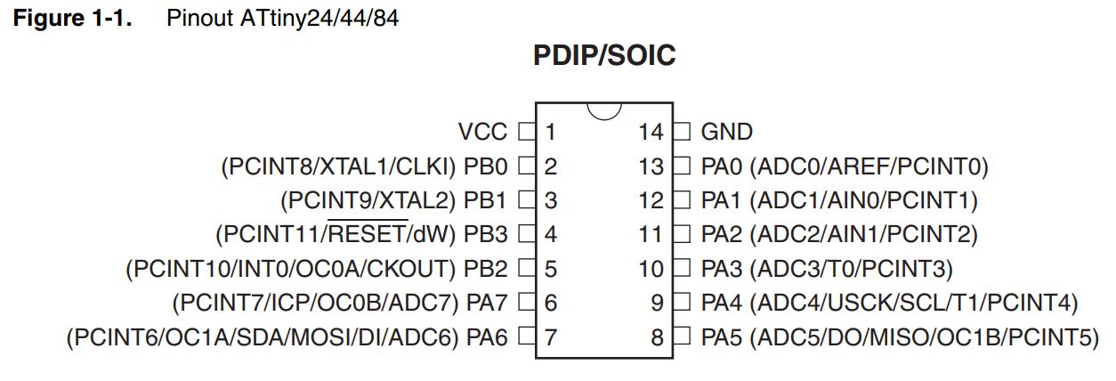
This is the pin layout found in the datasheet:
However, this layout is more visual and easy to understand:
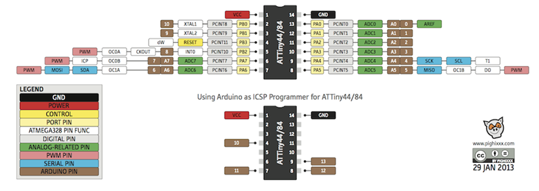
Some pins have a specific use, while others to which you can assign the function:
Some things I learned:
-The CPU core runs on the AVR architecture.
-The ATTiny24/44/84 chips have three different types of memory:
-Data Memory (Static and Dynamic RAM). SRAM memory is used for storing your data which is processed during the run time (including also the registers) - volatile memory
-The Program Memory is a reprogrammable flash memory that stores the program - non volatile. It can endure up to 10,000 write/erase cycles.
-EEPROM memory, can be used for storing non volatile data and changeable during run-time. (for example: setting values) Endurance: 100,000 Write/Erase Cycles
-The chip contains four different clocks: the CPU Clock, the I/O Clock, the Flash Clock and the ADC Clock. The internal oscillator is the default clock and it runs at 8mHz.
programming the board
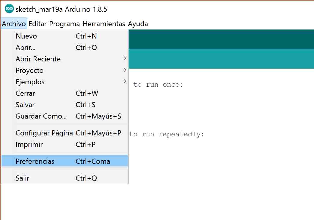
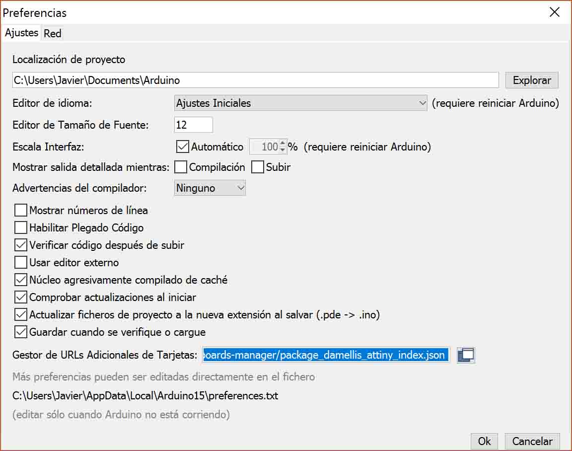
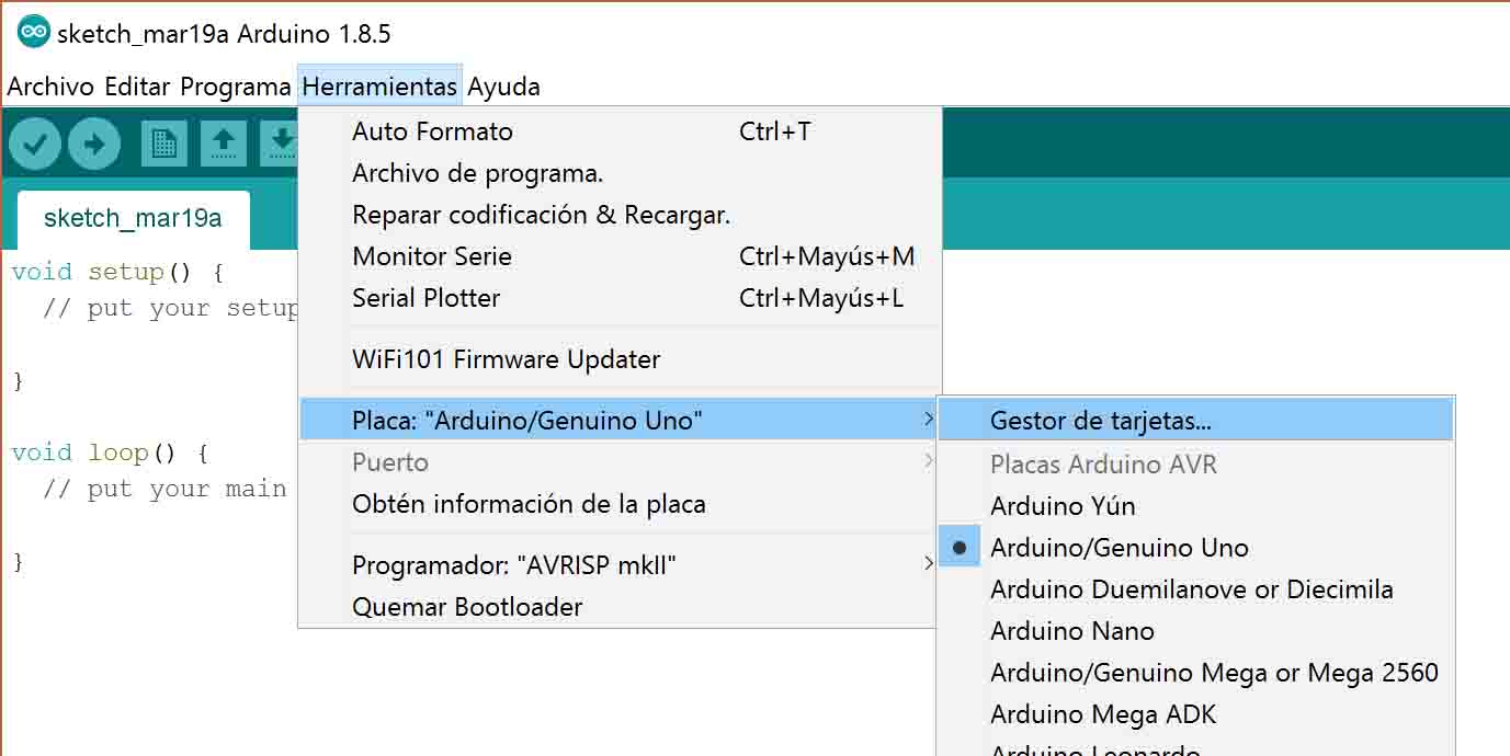
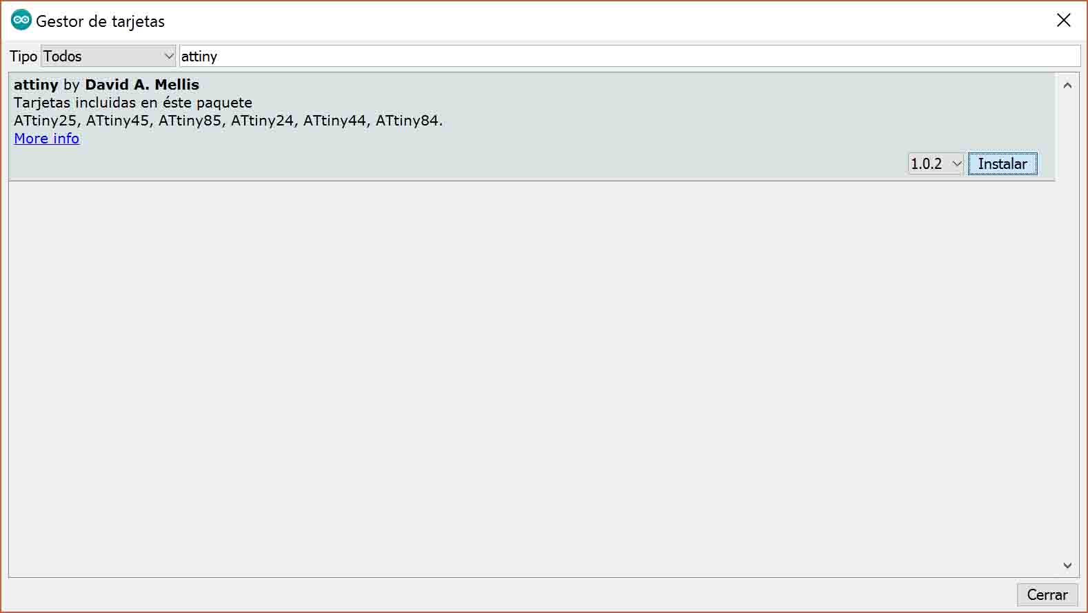
First you need to install ATtiny support in Arduino. I followed this tutorial, but basically the steps are:
We copy this into the "Additional Boards Manager URLs" field: https://raw.githubusercontent.com/damellis/attiny/ide-1.6.x-boards-manager/package_damellis_attiny_index.json
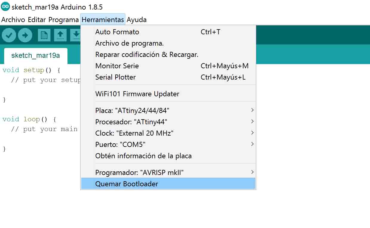
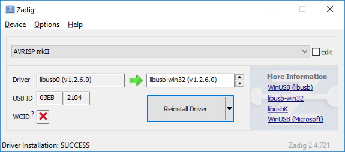
However, when burning the bootloader it doesn't work and an error appeared. Apparently it was a poblem of not detecting de AVRISP mkII and libusb-win32 drivers for Windows10 needed to be downloaded. Open the .zip, look for the inf-wizard.exe and generate the .inf file. If you check the Windows Device Manager, you will see the AVRISP mkII with a yellow sign. Download Zadig software to install the drivers. After that, that yellow sign should have disappeared.
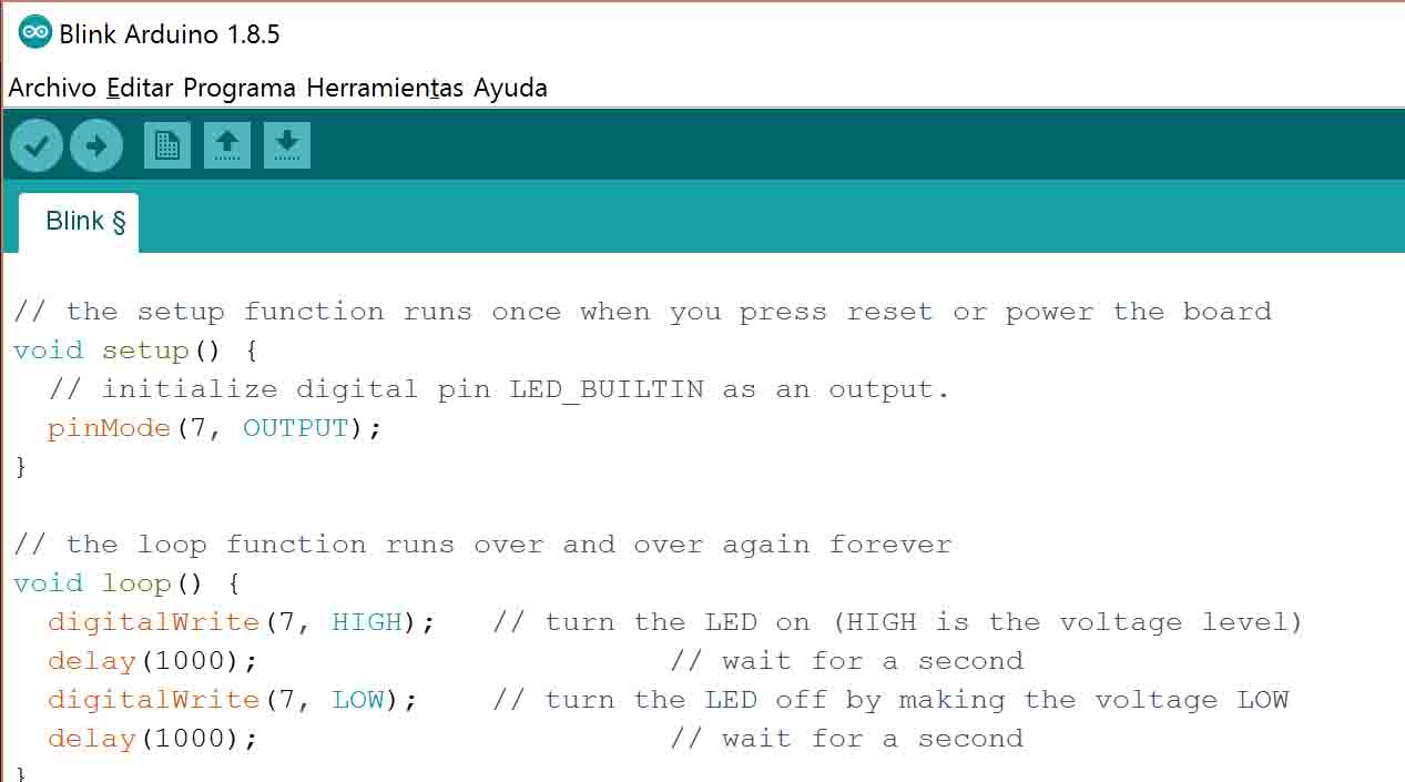
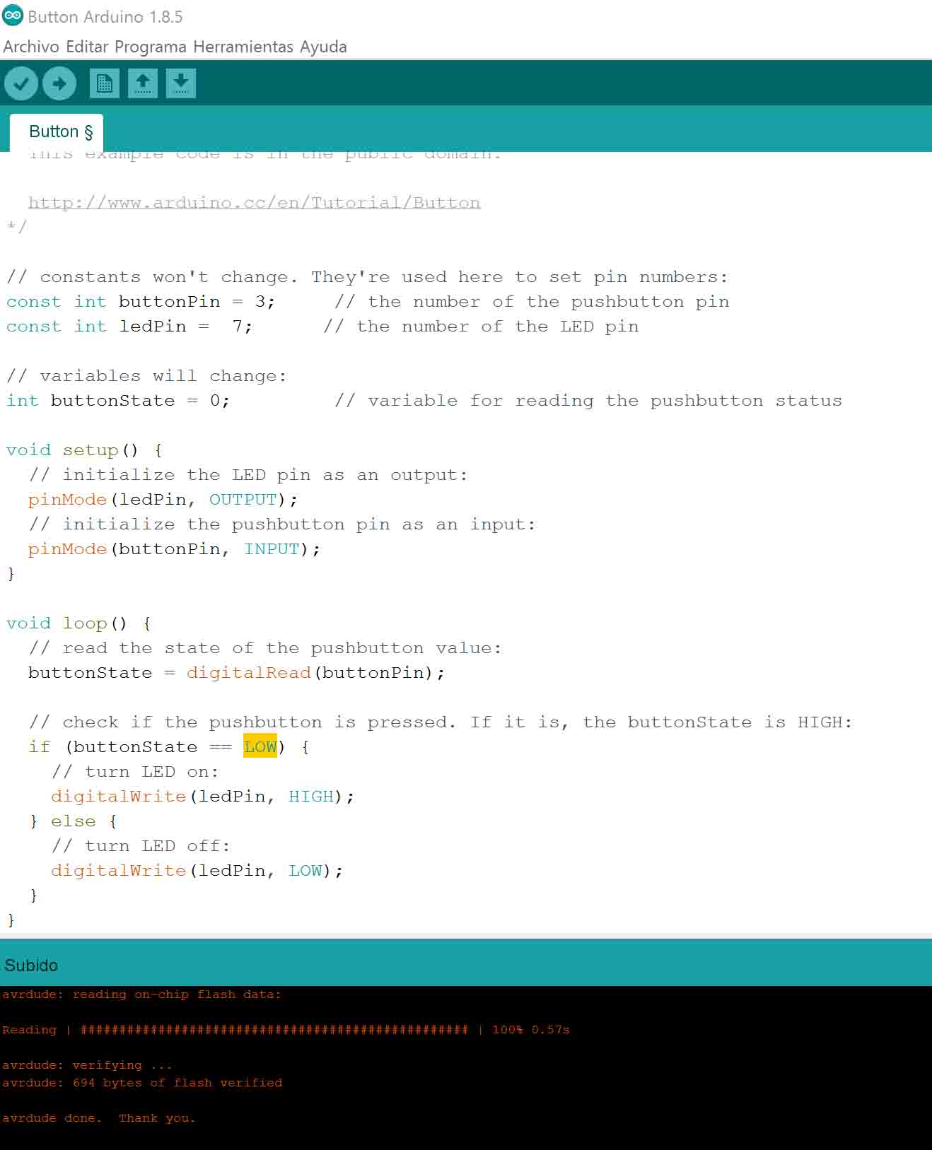
First I tried the 'blink' example:
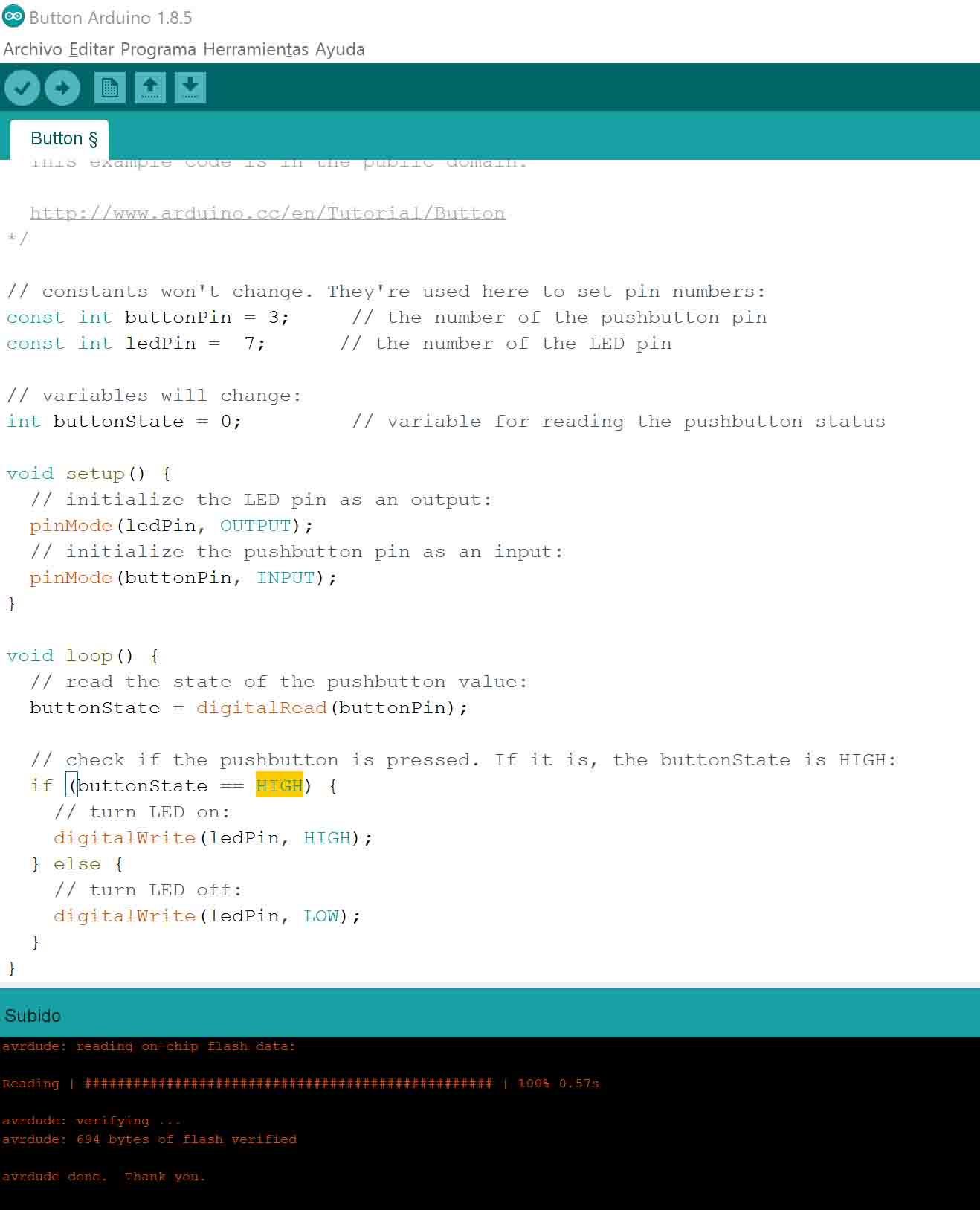
In the button example my LED ended up always ON, unless I pressed the button, which turned it off. I wanted it to be the opposite: LED off by default, and only being ON while pressing the button. In order to do that I changed the HIGH setting to LOW, as seen in the images. Apparently...
Then I decided to program the board in order to send an morse SOS via LED when the button is pressed:
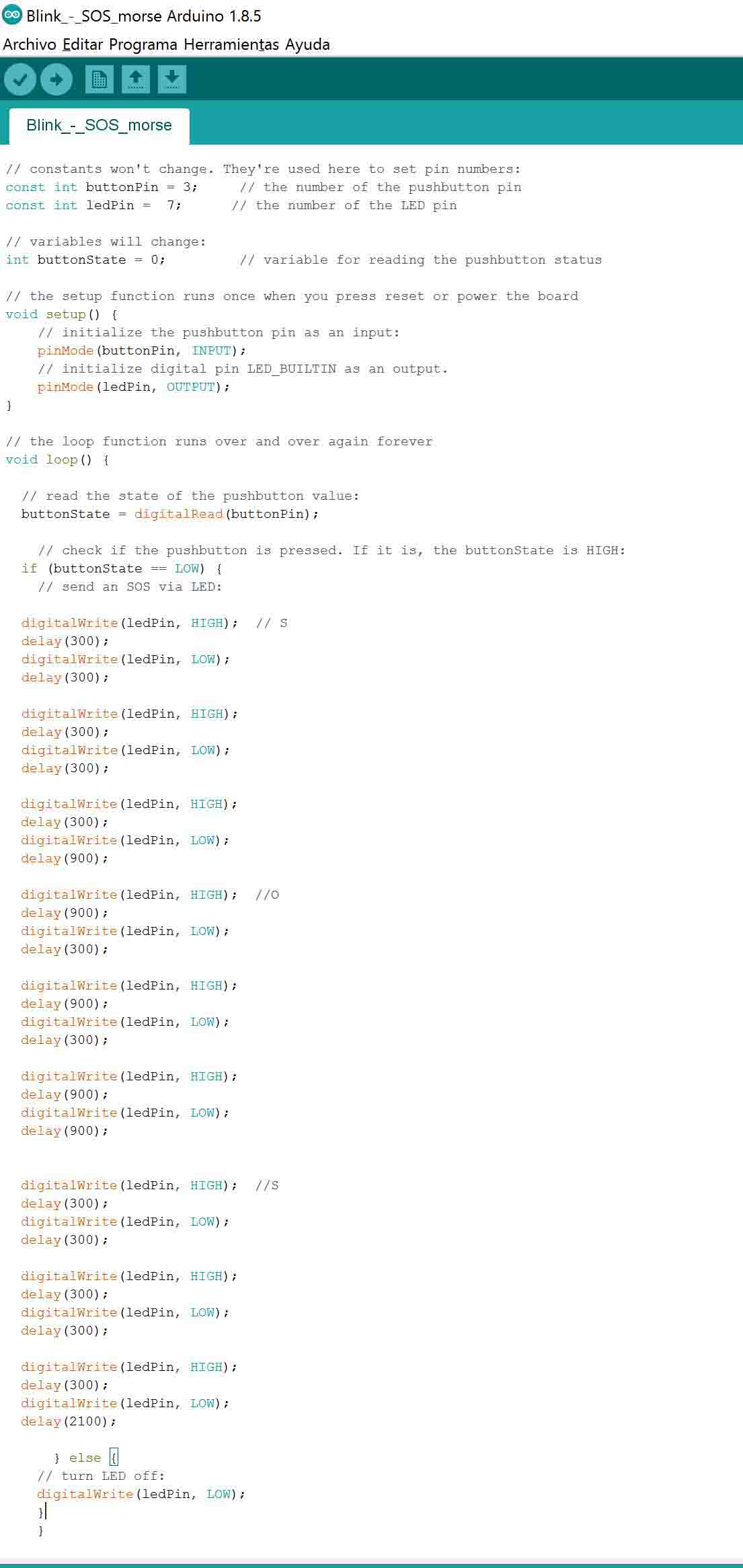
  // constants won't change. They're used here to set pin numbers:
  const int buttonPin = 3;     // the number of the pushbutton pin
  const int ledPin =  7;      // the number of the LED pin

  // variables will change:
  int buttonState = 0;         // variable for reading the pushbutton status

  // the setup function runs once when you press reset or power the board
  void setup() {
    // initialize the pushbutton pin as an input:
    pinMode(buttonPin, INPUT);
    // initialize digital pin LED_BUILTIN as an output.
    pinMode(ledPin, OUTPUT);
  }

  // the loop function runs over and over again forever
  void loop() {

    // read the state of the pushbutton value:
    buttonState = digitalRead(buttonPin);

    // check if the pushbutton is pressed. If it is, the buttonState is HIGH:
    if (buttonState == LOW) {
      // send an SOS via LED:

      digitalWrite(ledPin, HIGH);  // S
      delay(300);
      digitalWrite(ledPin, LOW);
      delay(300);

      digitalWrite(ledPin, HIGH);
      delay(300);
      digitalWrite(ledPin, LOW);
      delay(300);

      digitalWrite(ledPin, HIGH);
      delay(300);
      digitalWrite(ledPin, LOW);
      delay(900);

      digitalWrite(ledPin, HIGH);  //O
      delay(900);
      digitalWrite(ledPin, LOW);
      delay(300);

      digitalWrite(ledPin, HIGH);
      delay(900);
      digitalWrite(ledPin, LOW);
      delay(300);

      digitalWrite(ledPin, HIGH);
      delay(900);
      digitalWrite(ledPin, LOW);
      delay(900);


      digitalWrite(ledPin, HIGH);  //S
      delay(300);
      digitalWrite(ledPin, LOW);
      delay(300);

      digitalWrite(ledPin, HIGH);
      delay(300);
      digitalWrite(ledPin, LOW);
      delay(300);

      digitalWrite(ledPin, HIGH);
      delay(300);
      digitalWrite(ledPin, LOW);
      delay(2100);

    } else {
      // turn LED off:
      digitalWrite(ledPin, LOW);
    }
  }
And here it is working!
Arduino function delay()pauses the program for an amount of milliseconds specified as parameter. millis(), on the other hand, is a function that returns the amount of milliseconds that have passed since program start. For simple tasks such as blinking one led, this might not be that useful, but it will if we want to have several tasks running at the same time without pausing the entire code. However, just to start getting used to this function, I decided to write the same code as above, but using millis() instead.
download files

This work is licensed under a Creative Commons Attribution-NonCommercial-ShareAlike 4.0 International License.