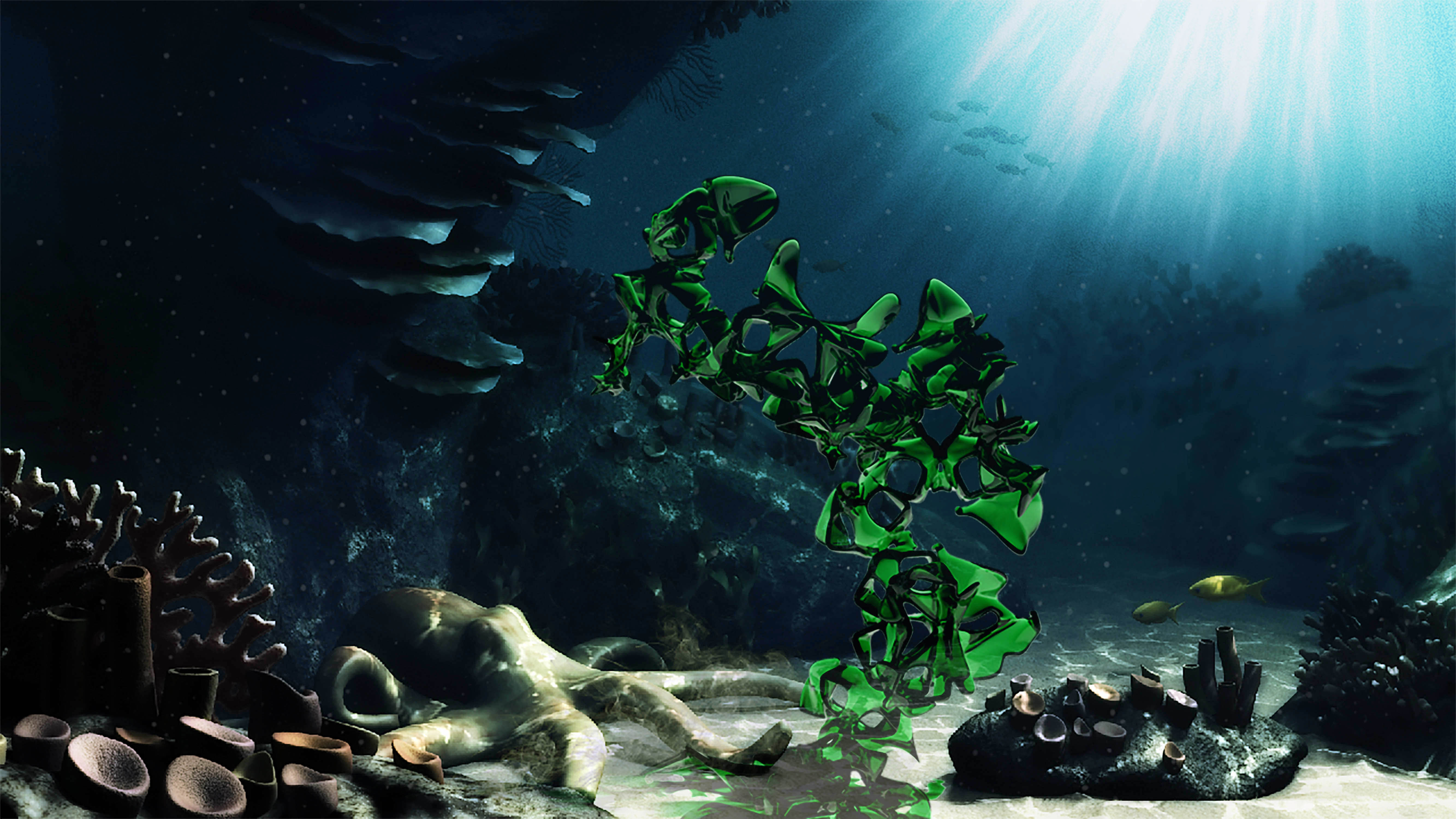
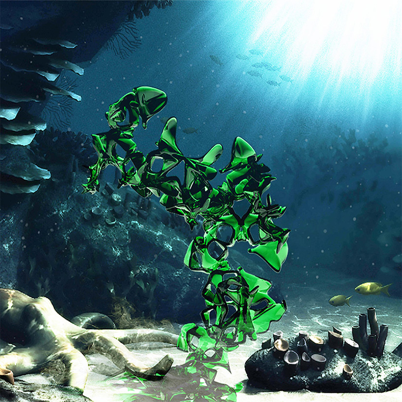
Computational morphogenesis makes it possible to generate biomimetic forms.
Bioplastic
Bioplastic made from 100% algae designed to return to the sea.
Marine Biology Data
We can use data to study the ecology of artificials reefs.
Assignments
Fabacademy Paris 2017 / VOLUMES / WOMA
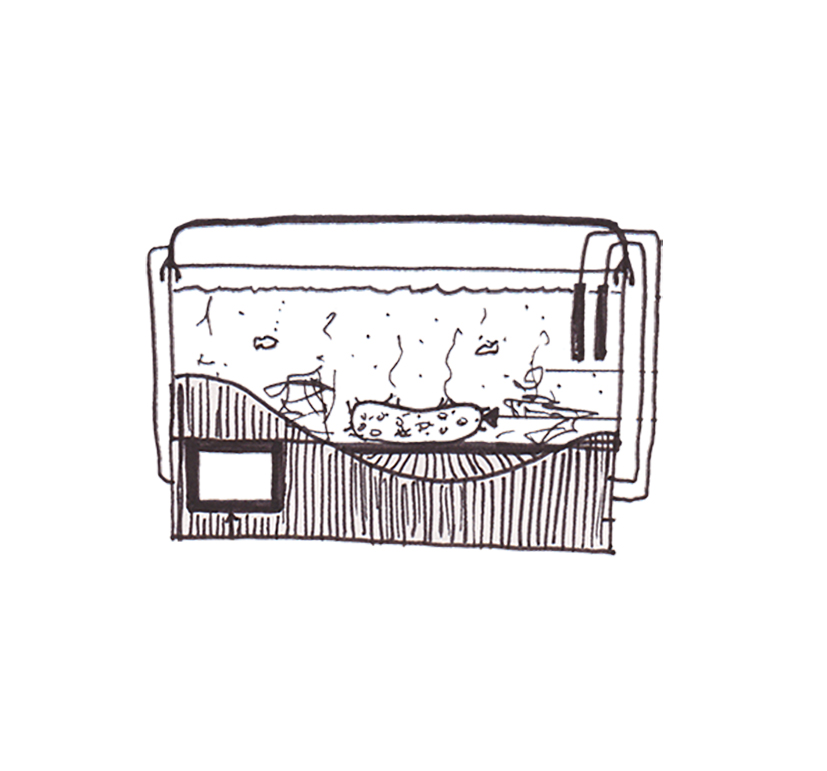
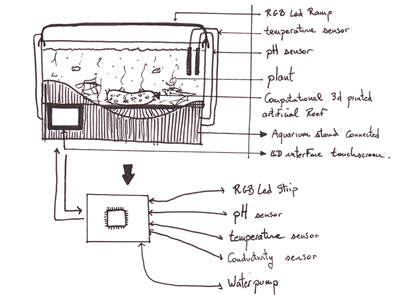
Sketch of final project
Week 1 - Project Management
Computational Artificial Reefs
Week 2 - Computer-aided design
Press fit kit
Week 3 - computer-controlled cutting
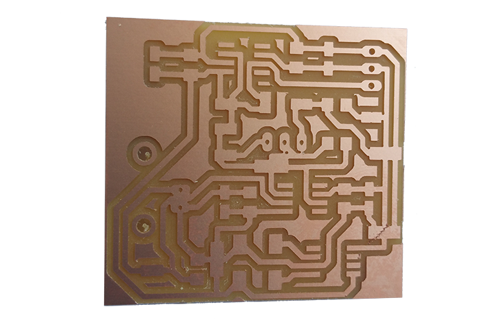
PCB Milling
Week 4 - Electronic production
Stereolithography 3D printing
Week 5 - 3D scanning / printing
Electronic design
Week 6 - Electronic design
CNC Milling
Week 7 - computer-controlled machining
Microcontrollers programming
Week 8 - Embedded programming
Gear design
Week 10 - Output Devices
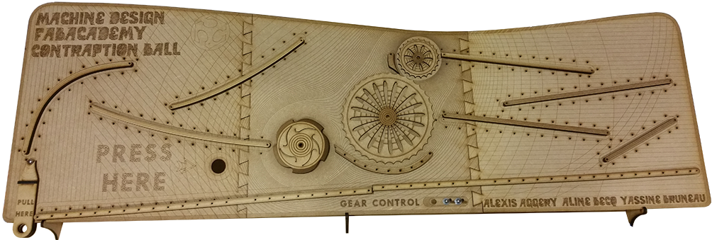
Contraption ball design
Week 11 - Machine design
Mold Biomimmetic patterns
Week 12 molding / casting
Sound input
Week 13 - Input devices
Tore composite
Week 14 - Composites
I²C protocol and logical analyzer
Week 15 - Networking and communications
interface programming
Week 16 - Interface and Application Programming
connected artificial reef system
Process of the Final project
FINAL PRESENTATION
FINAL PROJECT
Invention, Intellectual Property and Business Models
CC
About
Project progress
Januar 2017
Sketch the concept
A connected seaweed to study artificials reefs for the future ! Today artificial reefs, unknown to the general public, do not integrate into the submarine landscape. This experimental biomimetric project proposes the use of numerical design tools as well as the use of biomaterials in a complex ecosystem of marine biology.
February 2017
Experimental forms
Lorem ipsum dolor sit amet, consectetur adipisicing elit. Sunt ut voluptatum eius sapiente, totam reiciendis temporibus qui quibusdam, recusandae sit vero unde, sed, incidunt et ea quo dolore laudantium consectetur!
March 2017
Embedded programming
Lorem ipsum dolor sit amet, consectetur adipisicing elit. Sunt ut voluptatum eius sapiente, totam reiciendis temporibus qui quibusdam, recusandae sit vero unde, sed, incidunt et ea quo dolore laudantium consectetur!
April 2017
Phase Two Expansion
Lorem ipsum dolor sit amet, consectetur adipisicing elit. Sunt ut voluptatum eius sapiente, totam reiciendis temporibus qui quibusdam, recusandae sit vero unde, sed, incidunt et ea quo dolore laudantium consectetur!
Be Part
Of Our
Story!
Team
Hello ! My name is Yassine BRUNEAU. I am 26 years old, i am a young architect, passionated about Diy, Opensource, Collaborative spirit, Digital revolution, biology, complex geometries and digital technology in architecture.
Yassine Bruneau
Architect
Contact me
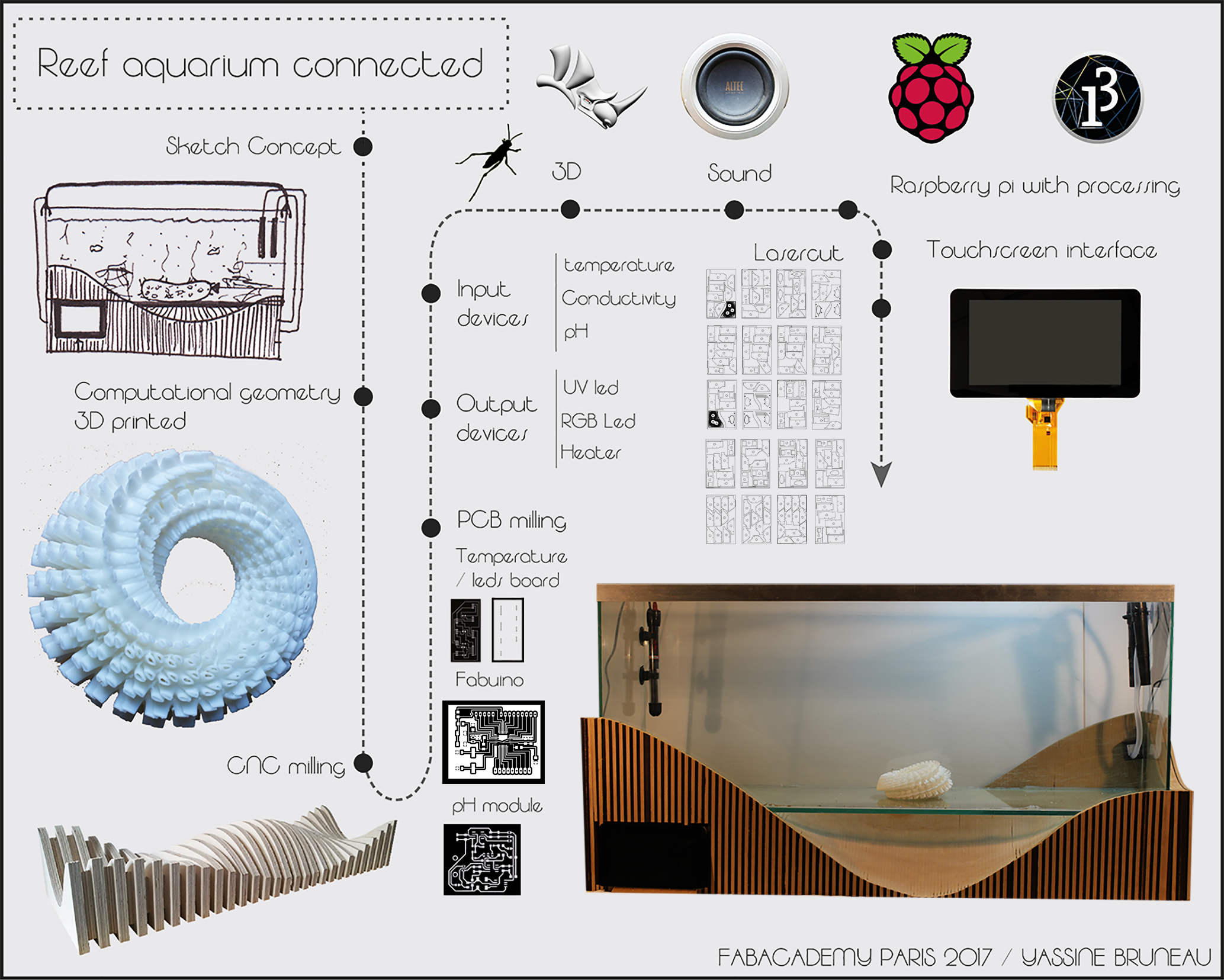
My PROJECT : A Connected seaweed
Artificials reefs for the future !
Today artificial reefs, unknown to the general public, do not integrate into the submarine landscape. This experimental biomimetric project proposes the use of numerical design tools as well as the use of biomaterials in a complex ecosystem of marine biology.
The biomimetic forms will be generated by computers and manufactured using numerical control machine. They will be tested to see if they offer an ecological niche favorable to the development of certain species. These observations will make it possible to
The computer code to the natural selection in order to reveal the morphogenetic parameters which have observable effects on the marine life. The second part of this project is to study the possibility of capturing data such as temperature or light in order to quantify these observations. At the end of this fabacademy the objective is to develop a prototype of coral artificial connected that captures data and to visualize them on a computer.
Fabacademy 2017
Yassine BRUNEAU
Januar 2017
Sketch of the project
Developing a website using HTML and CSS with Bootstrap and Atom
Bootstrap is a free and open-source front-end web framework for designing websites and web applications. It contains HTML- and CSS-based design templates for typography, forms, buttons, navigation and other interface components, as well as optional JavaScript extensions. Unlike many web frameworks, it concerns itself with front-end development only.
Step 2 : Create a new folder where you can unzip inside your bootstrap files
Now, you have your website files inside the folder you created.
Atom is a text editor that's modern, approachable, yet hackable to the core—a tool you can customize to do anything but also use productively without ever touching a config file.
Step 4 : Open Atom and open your new folder
Inside Atom, Click to index.html, to see the html code of your future website.
The HTML code give the information of the contents of your website.
Inside Atom, Click on the agency.css file inside the folder named "css". Now you cn see the CSS code who give the information of the style/aspect of your website
Step 5 : Open your index.html files with your web navigator
Click right with your mouse an click to "inspect". A new windows openedin your navigator. You can see simultaneously the HTML code and the CSS modules.
You can click and change them to simulate what's happen if you modify to code and make your own design.
Step 6 : Find an html/css ressources to learn how design your website !
You can go to w3schools or openclassroom to learn very quickely how tochange the HTML and CSS code.
Good luck !
GIT tutorial
Git is a version control system for tracking changes in computer files and coordinating work on those files among multiple people. It is primarily used for software development, but it can be used to keep track of changes in any files. As a distributed revision control system it is aimed at speed, data integrity, and support for distributed, non-linear workflows.
Download the setup files wich corresponding with your os. install it.
Step 2 : Generate your SSH key
launch Git Bash, you have a command line who appears. write "cat ~/.ssh/id_rsa.pub". it will generate your SSH key.
You can connect you to gitlab here.
You can save your ssh key to identify your computer ans save your work safely.
Step 3 : Upload your work !
You have 4 commands to execute inside the command line to save your work every week in this order :
- git pull
- git add -A
- git status
- git commit-m "write a commit of your work"
- git push origin HEAD
Step 4 : To learn more about git commands, you can go here.
Computational artificial reefs !
Made with Rhinoceros 3D + Grasshopper
Grasshopper is a graphical algorithm editor tightly integrated with Rhino’s 3-D modeling tools. Unlike RhinoScript, Grasshopper requires no knowledge of programming or scripting, but still allows designers to build form generators from the simple to the awe-inspiring.
How to modelise complex geometries?
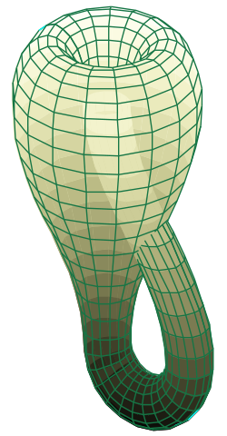
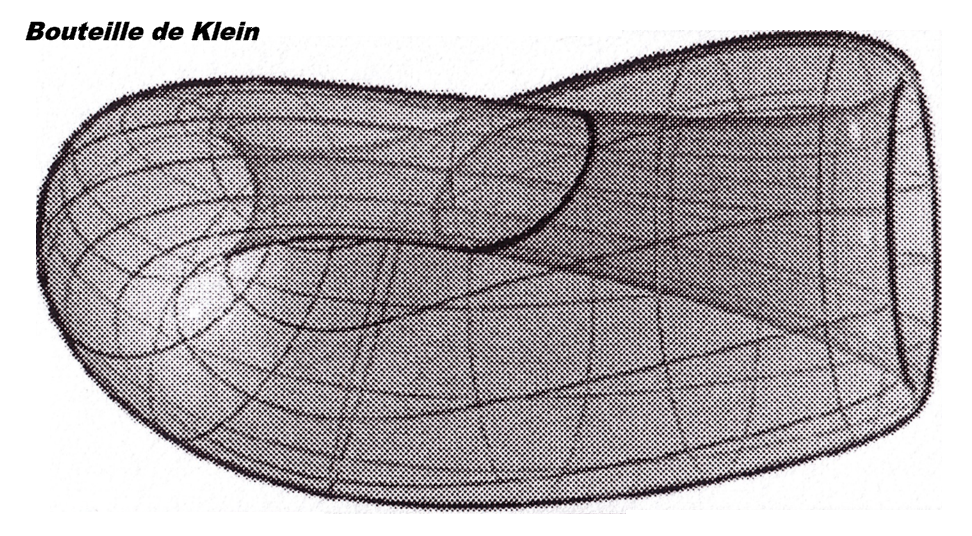
Example of the Klein bottle
In mathematics, the Klein bottle /ˈklaɪn/ is an example of a non-orientable surface; it is a two-dimensional manifold against which a system for determining a normal vector cannot be consistently defined. Informally, it is a one-sided surface which, if traveled upon, could be followed back to the point of origin while flipping the traveler upside down. Other related non-orientable objects include the Möbius strip and the real projective plane. Whereas a Möbius strip is a surface with boundary, a Klein bottle has no boundary (for comparison, a sphere is an orientable surface with no boundary.
Moebius Strip
Moebius, is a surface with only one side (when embedded in three-dimensional Euclidean space) and only one boundary. The Möbius strip has the mathematical property of being unorientable. It can be realized as a ruled surface
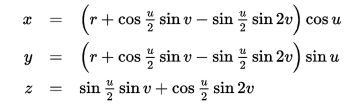
Modelisation of the "figure 8" of the klein bottle
To make the "figure 8" or "bagel" immersion of the Klein bottle, you can start with a Möbius strip and curl it to bring the edge to the midline; since there is only one edge, it will meet itself there, passing through the midline. It has a particularly simple parametrization as a "figure-8" torus with a half-twist:
Parametrization : Maths to 3D algorithms with grasshopper
It is a visual 3d coding tools as a framework that allows to easily parameterize the geometric models of complex geometry.
You can use every 3D tools or 2D tools in Rhino to create a simple surface.
Step 3 : Launch grasshopper
To launch grasshopper, you have to write the command " grasshopper " inside the Rhino command bar.
Step 4 : Open your script inside grasshopper
You can download this grasshopper example file HERE
To open the file, you can move it inside the grasshopper windows. Now you can see your visual framework script.
Step 5 : Apply your grasshopper script to your rhino target surface.
How to Draw Fabacademy logo with illustrator ?
Step 1 : Open Illustrator software
We make contact with the interface of this wonderful graphic design software. Unlike Photoshop or Gimp that work with pixels.
Illustrator is a vector software. it is widely used among other things to create logo or illustration.
On the left, we have graphic editing tools. On the right, we find the management of effects and layers.
At the top, we have a toolbar that changes depending on the tools selected
Step 2 : Import one image as a background
To import an image, simply select this one and move on our illustrator sheet.
Then we can change its size thanks to the handles of change of scale. Just keep shift pressed to maintain the proportions when changing the scale.
Step 3 : Placer l'image dans un calque en arriere plan
To place an image in a layer, just select the image and click in the layer management tab on the small blue square,
keep the click and drag the square in the line of the layer where you want place the picture.
Then you have to lock the layer in order to draw on it without affecting the background image.
Step 4 : Select the "Pen" tool
The pen tool is located in the toolbar on the left, at the top
Step 5 : Bend the curves with tangents.
Correctly bend the curves with tangents.
Step 6 : Invert background color and outline color
We need to color the inside of the letters A and B in white. We detour these spaces but we click on an icon which allows to invert the background color and the outline of the selected zones.
Step 7 : Use the text tools
To realize the letters faster. it is better to use the text tools while keeping the same character font
Step 8 : Change the color of the background and the logo.
To finish this wonderful moment of creation, I propose you to select the rectangle tools and to assign the black color to it.
I propose you to to assign the black color to your rectangle in back ground.
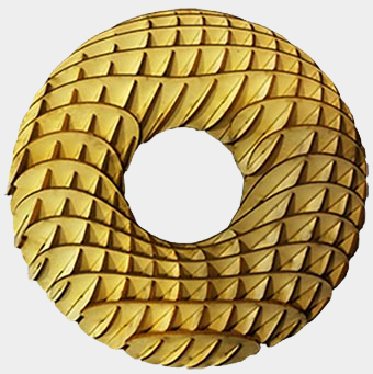
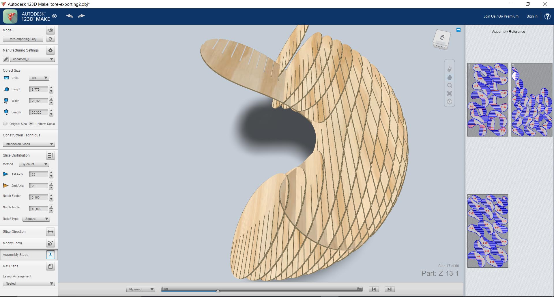
How to make a simple parametric press fit kit with 123D make
This week, I decided to experiment with an Autodesk software named 123Dmake to generate press fit kit with rounded shapes or even complex geometry.
This software is presented as a turnkey solution with tools of numerotatins of the parts, numerotation of the boards and the optimization of the plates to be cut with the laser thanks to the preparation of the dimensions of the materials.
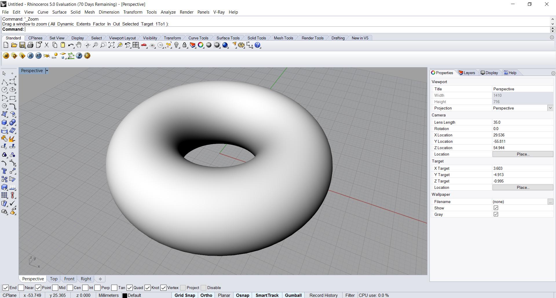
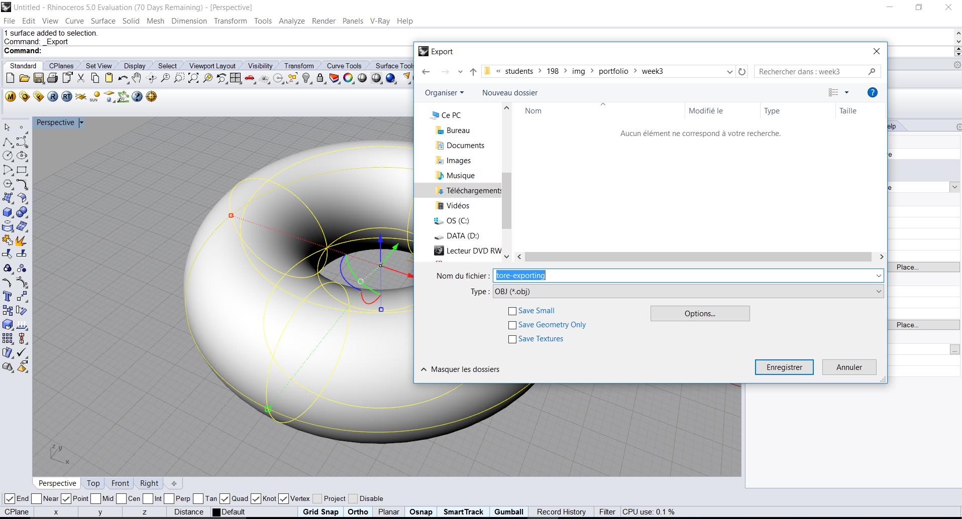
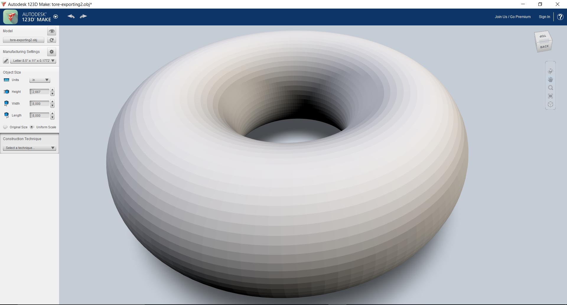
Step 1 : Draw something and export it in OBJ
First we will draw our geometry in a 3D software so we can draw the curves that we wish to give our press fit Kit. To do that, i used Rhinoceros 3D to make a very simple closed surface like a torus.
In order to transmit the information from one software to the other, we need to transcribe it in a common language. We must export our file to an extension that is readable by the target software. In this case we are going to use the .obj file format which is a very used 3D model extension file.
Step 2 : describe parametric 3D and 2D modelling final processe
After opening the software 123Dmake, I import my geometry tore in .obj, and here is what happens. The interface of this software is quite simple on the left, we have a series of information which are the parameters of the material: width, length, thickness. It is possible to customize material preferences in case you often need to cut out the same material.
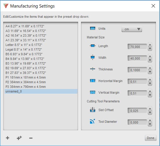
When one clicks on manufacturing setting, one arrives on this window which contains all the parameters related to the manufacture,
It is here that I adjust the cut to my carton and my preferences of cutting
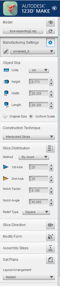
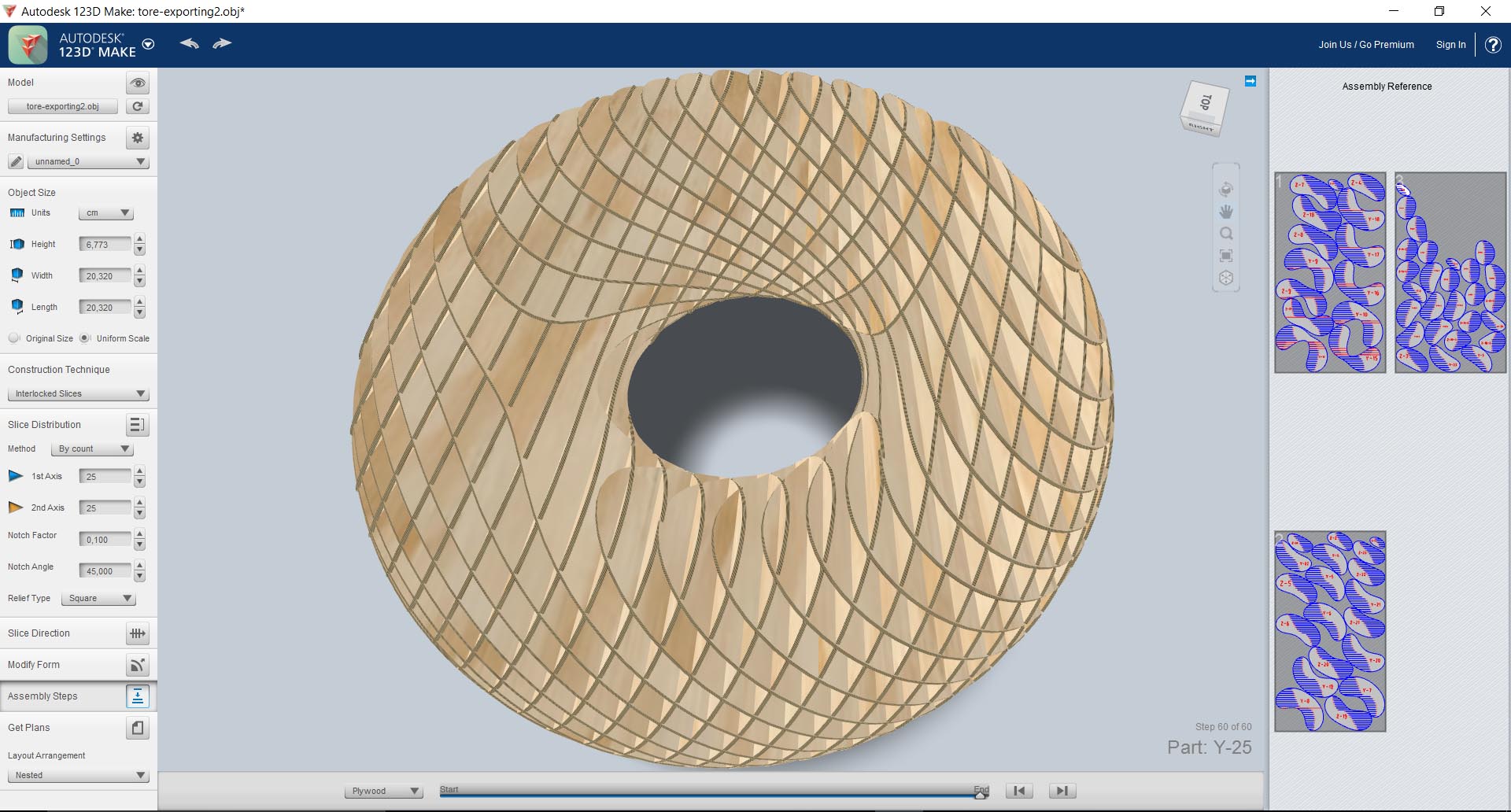
This new window, directly accessible on the left, allows to adapt the method of construction and assembly of the cut object. And all the geometric factors that decompose the shape of the final object..
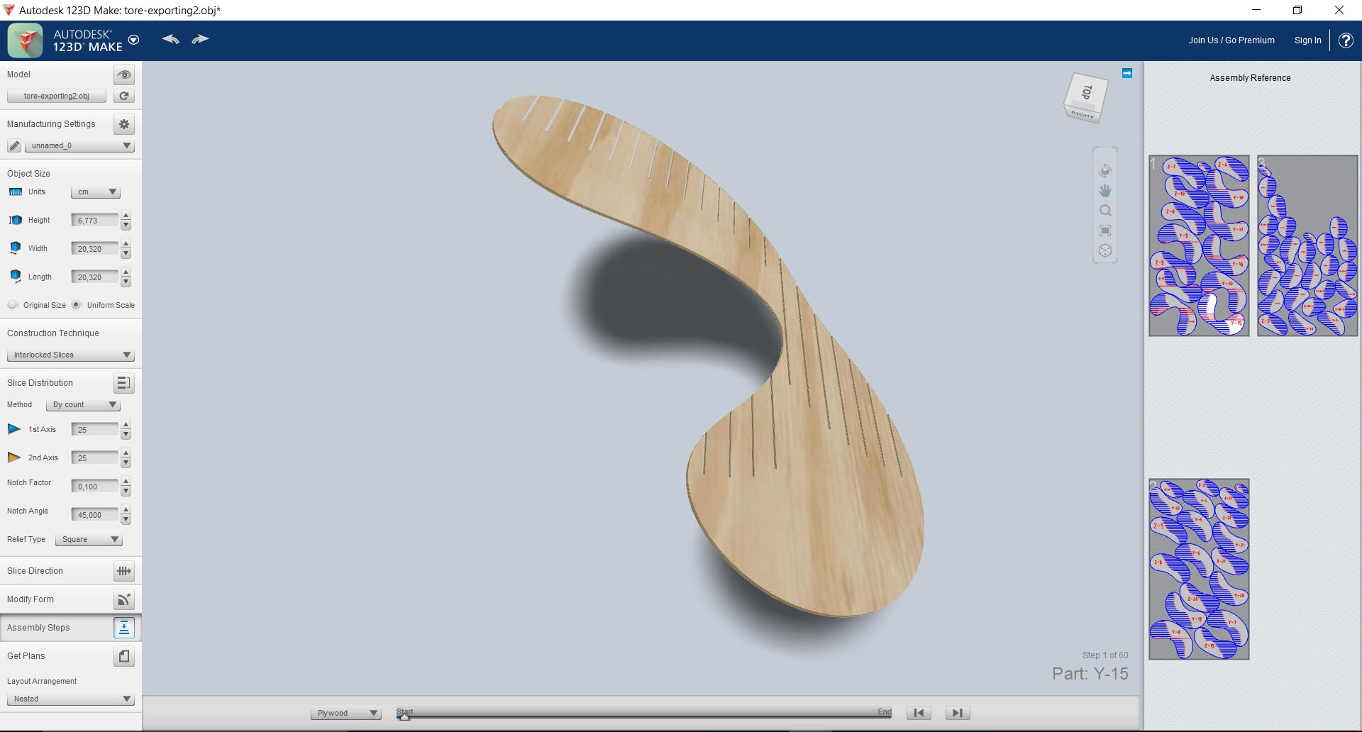
In the three images which follow one sees the object being assembled and constructed. Effectively 123Dmake includes a simulation tools of the assembly. Caution in many cases a number of factors are not taken into account in the software such as the expansion, elongation of the materials, its flexibility and this profoundly changes the data to the assembly. Some objects will be impossible to assemble given the number of friction generated by the different parts.
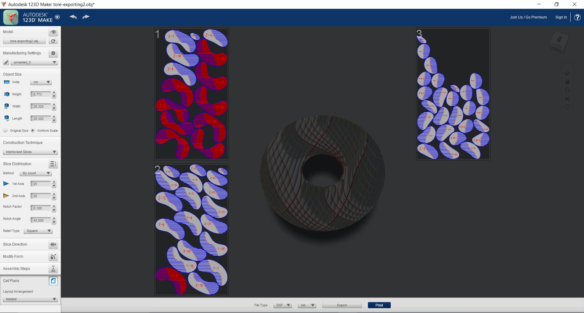
Now you have generated your cut board, you are ready to export your model in.dxf and cut your object !
Step 3 : Open your 2D DXF with AutoCAD
I opened the infile into AutoCAD to prepair the file to the lasercutter. On autocad I must now assign line colors to each machining, cutting, plotting, engraving so that laser cutting can sort the order and the natures of the different actions to perform.
Step 4 : Export your file to TrotecJob
To send the file to the laser cutting control software, click on file - print and select the driver of the Trotec 300 laser in the same way as if you want to print on an inkjet printer.
Step 5 : Set the parameters to cut with Trotecjob to control your lasercutter
In this window you can pametrate each color nottament by playing with the speed and power of the laser. The lasercut can cut, trace or etch according to the parameters. Each color is assigned to a particular order. In the occurance on the lasercut of the range trotec a code coueur is imposed which defines the order with which the machine will carry out the jobs.
In the window below on the left, the machine estimates the cutting time necessary to complete the cutting of the fihier. As well as the time for each job.
Finally here is an image of laser cutting cutting our file.
This is the first board we cut. The parts thus cut on the cardboard are directly selfassembling.
Step 6 : Result after assembly the press fit kit
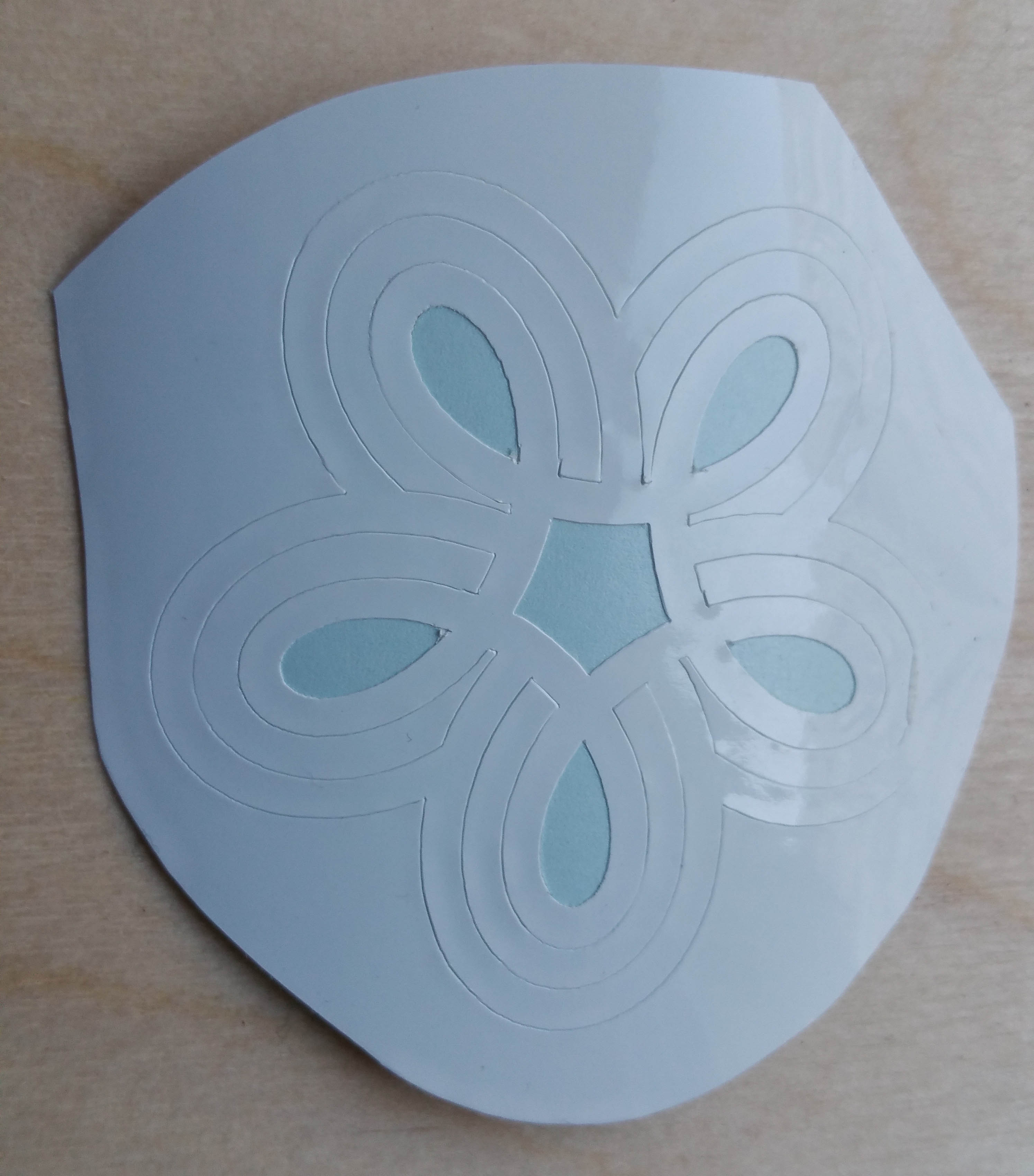
Use the vinyl cutter
Step 1 : Draw a 2D parametric model with Rhino / Grasshopper
To model the cut-out pattern with the vinyl cutter i use rhinoceros 3D ith grasshopper to simulate a spirograph as described in this video. I export my file in DXF. Then I opened this DXF file with the Proprietaire software of the Silhouette Cameo vinyl cutter
Step 2 : Using the vinyl cutter
The CAMEO silhouette is the ultimate DIY machine . It connects to your PC with a simple USB cable. The CAMEO Silhouette uses a small blade to cut over 100 different materials, including paper, cardboard, vinyl and fabric up to 30 centimeters wide and 3 meters long. When replacing the blade with a pen, the CAMEO can also draw and dotted. The machine has the ability to cut out printed images with the marker detection system and is PixScan compatible.
The position of the tools is indicated with a red circle on the left and a blue circle on the right. Insert your tools (an AutoBlade blade and a Silhouette pen) into the corresponding tool holders you assigned in your cut-out settings in Silhouette Studio®. Your machine performs two different functions in succession for a single cutting job. Using the left toolholder allows automatic adjustment of the blade length.
CAMEO vinylcutter has a raised training bar (2 mm) compared to previous CAMEOs. This allows you to load and cut thicker materials * using the deep cutting blade.
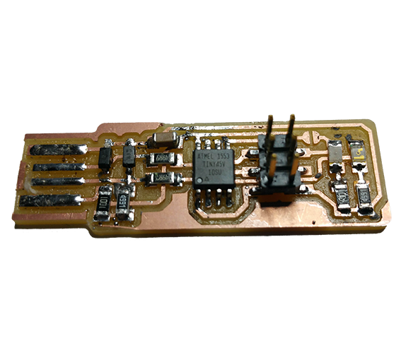
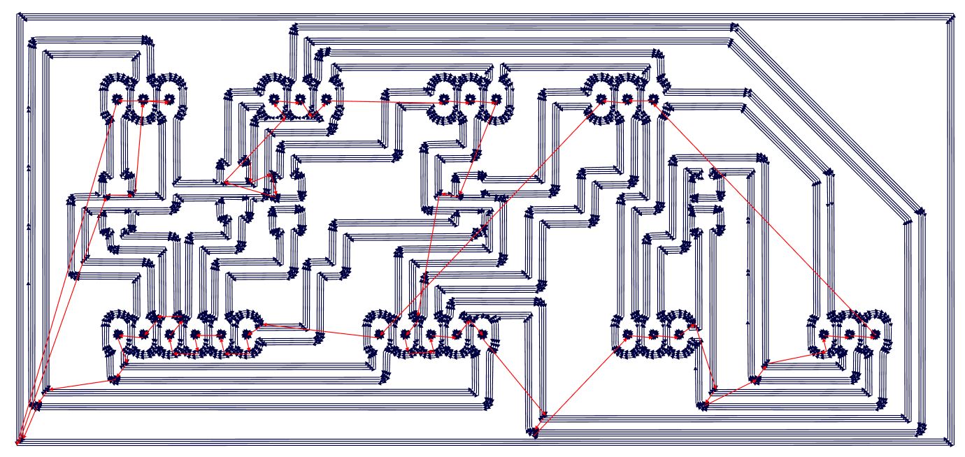
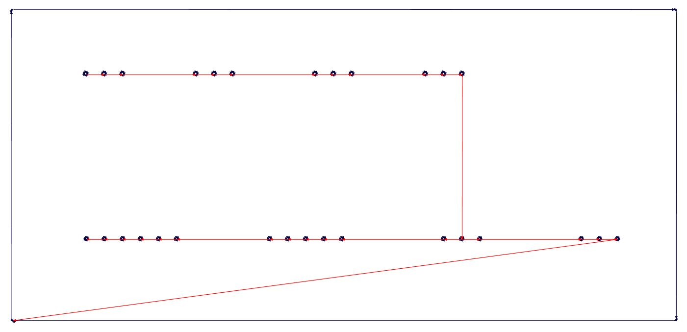
This week, we will learn how make our own Programmer board. I take the expample of brian's programmer
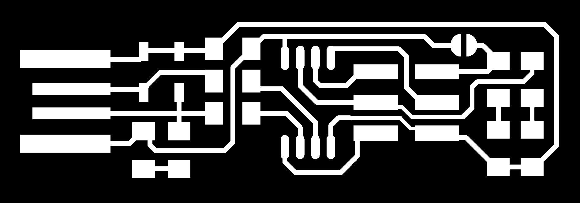
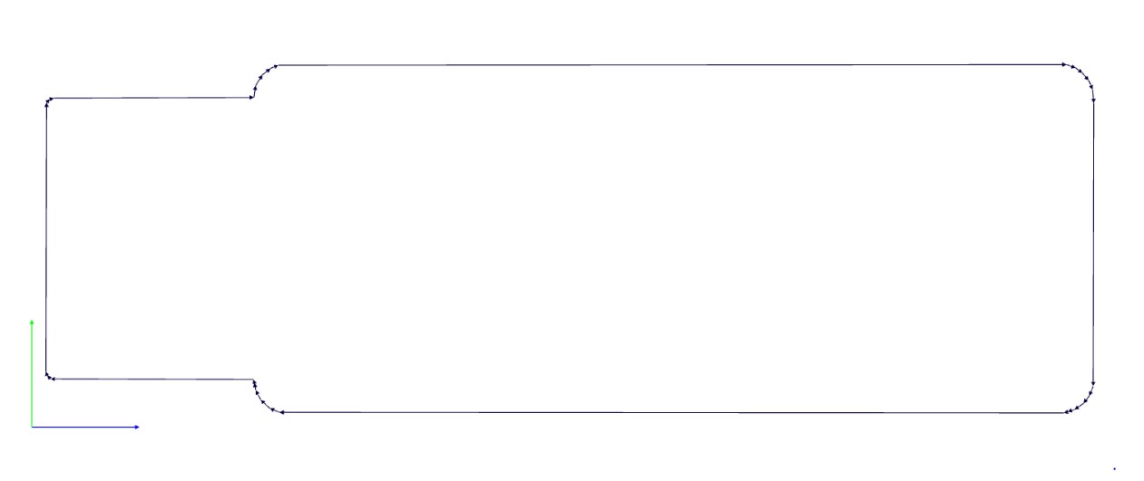
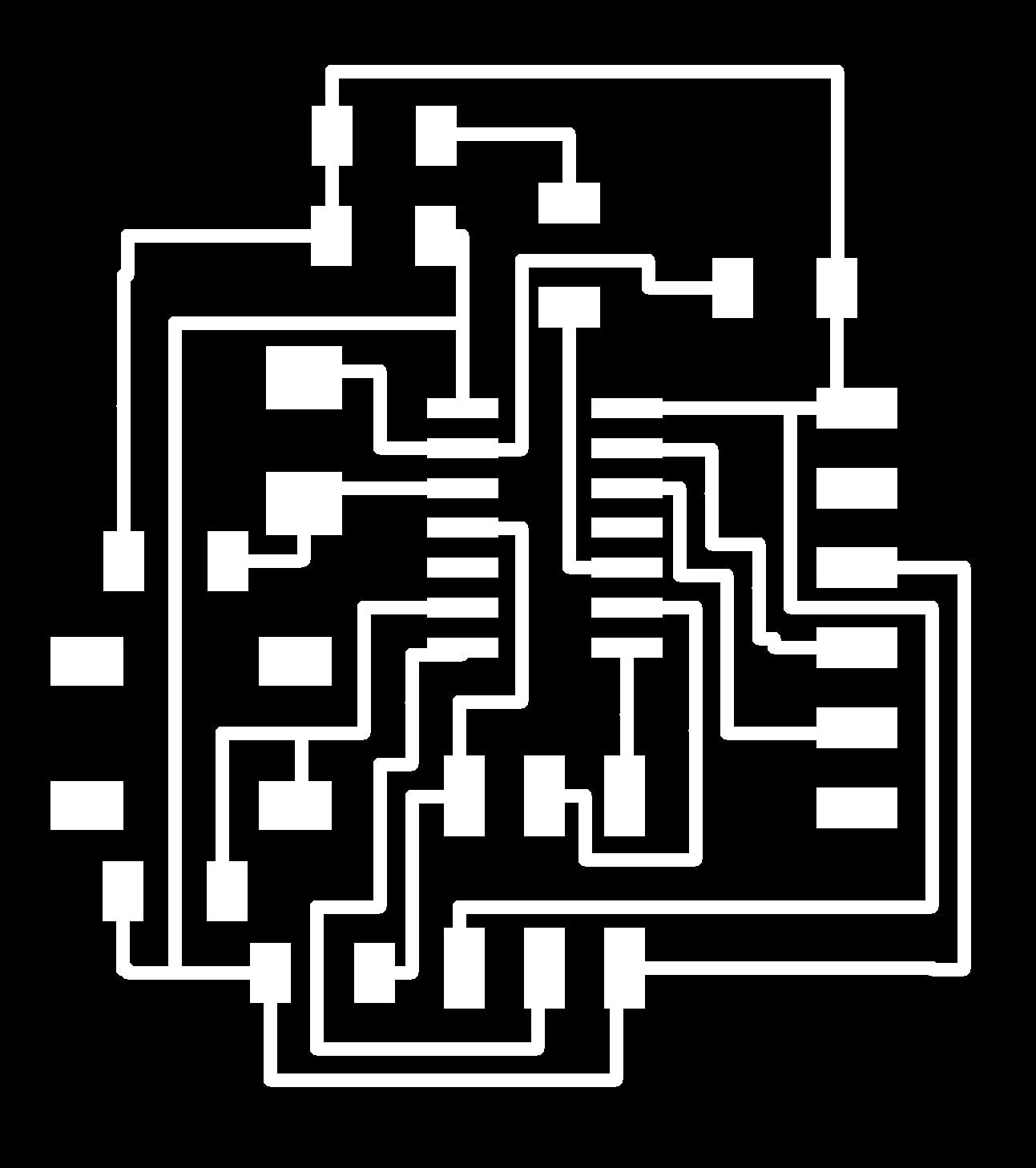
Step 1 : Draw your circuit with gimp or photoshop
You have to make two importants files : one for the traces of your circuit and one for the outlines to cut the border of the board.
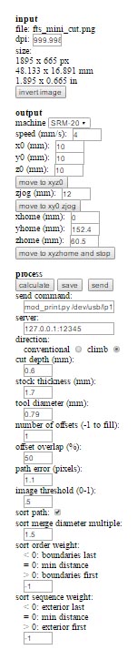
Step 2 : Use fabmodule to generate the G-Code
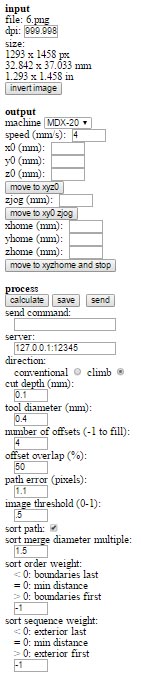
You have to go to fabmodule.org
You click to input format to choose the format of your file. For me i choose .Png.
You have to verify the size and the resolution of your file (.png)
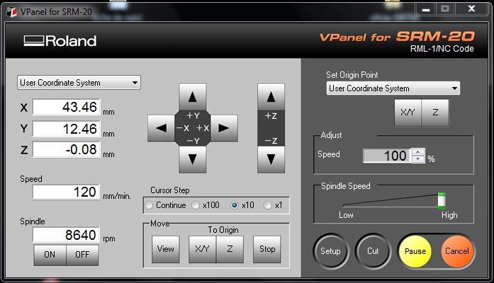
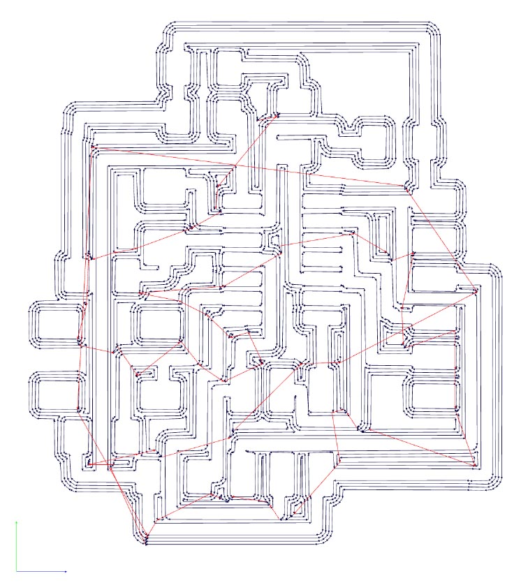
You have to define the output. For us we chose .rlm because we have a Roland SRM-20 milling machine.
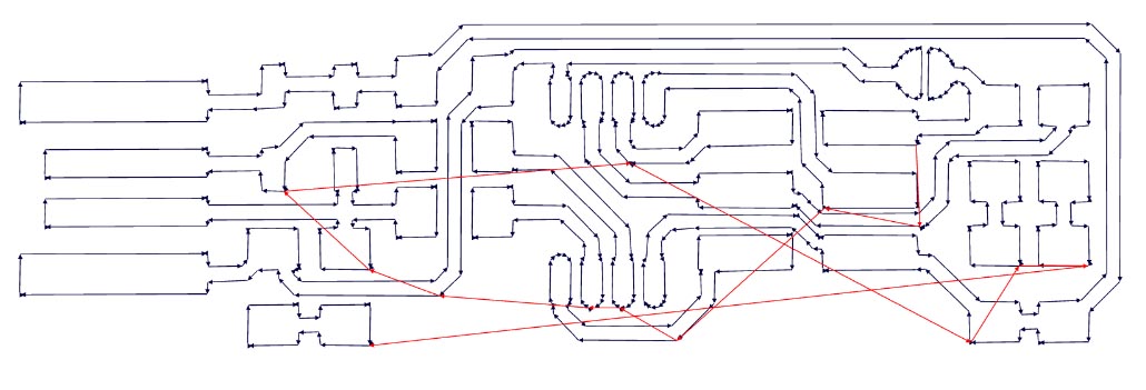
And define parameters of milling in the process parameters and click on calculate to generate the gcodefile. To finish , click save to download your g-code file.
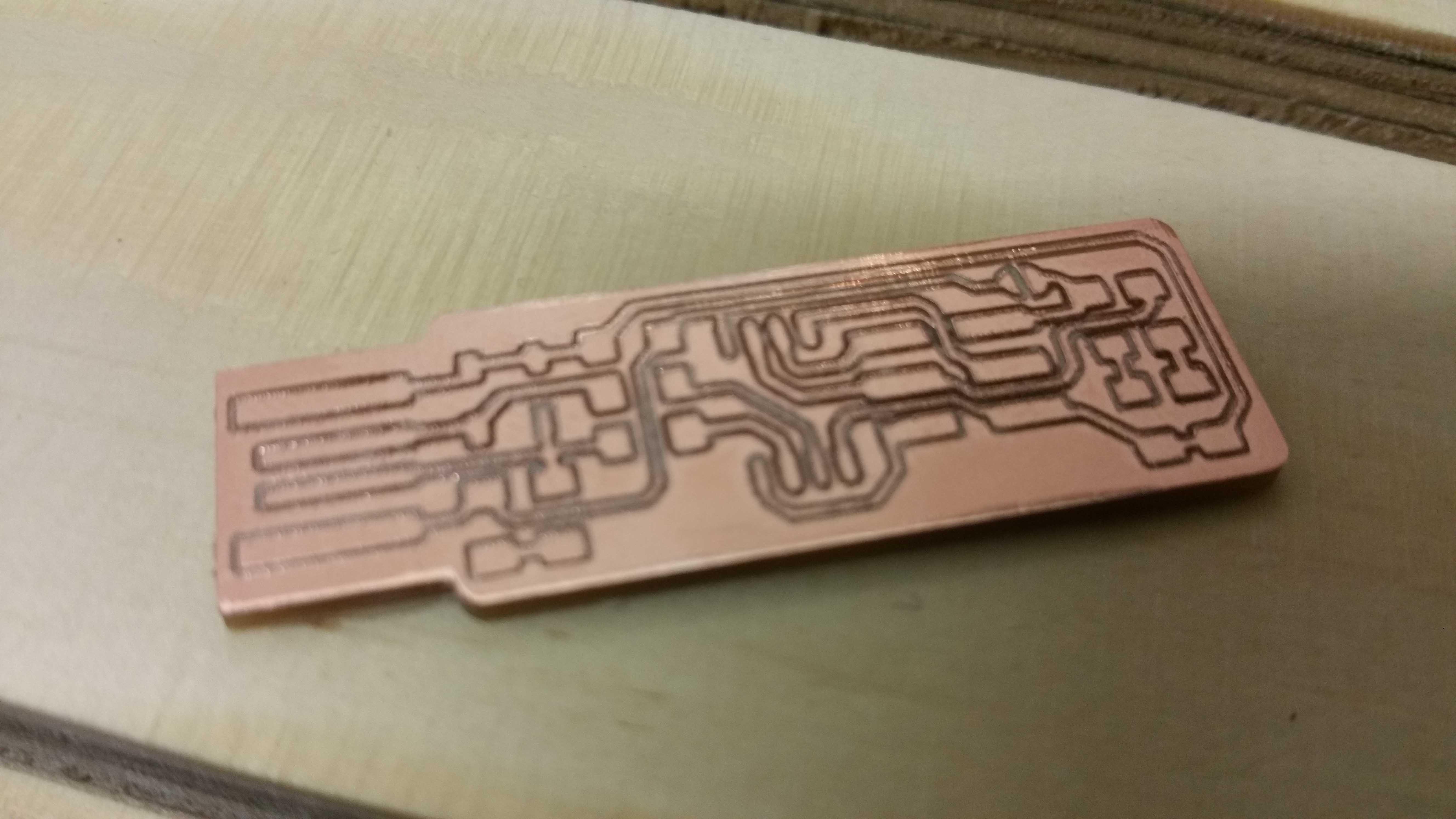
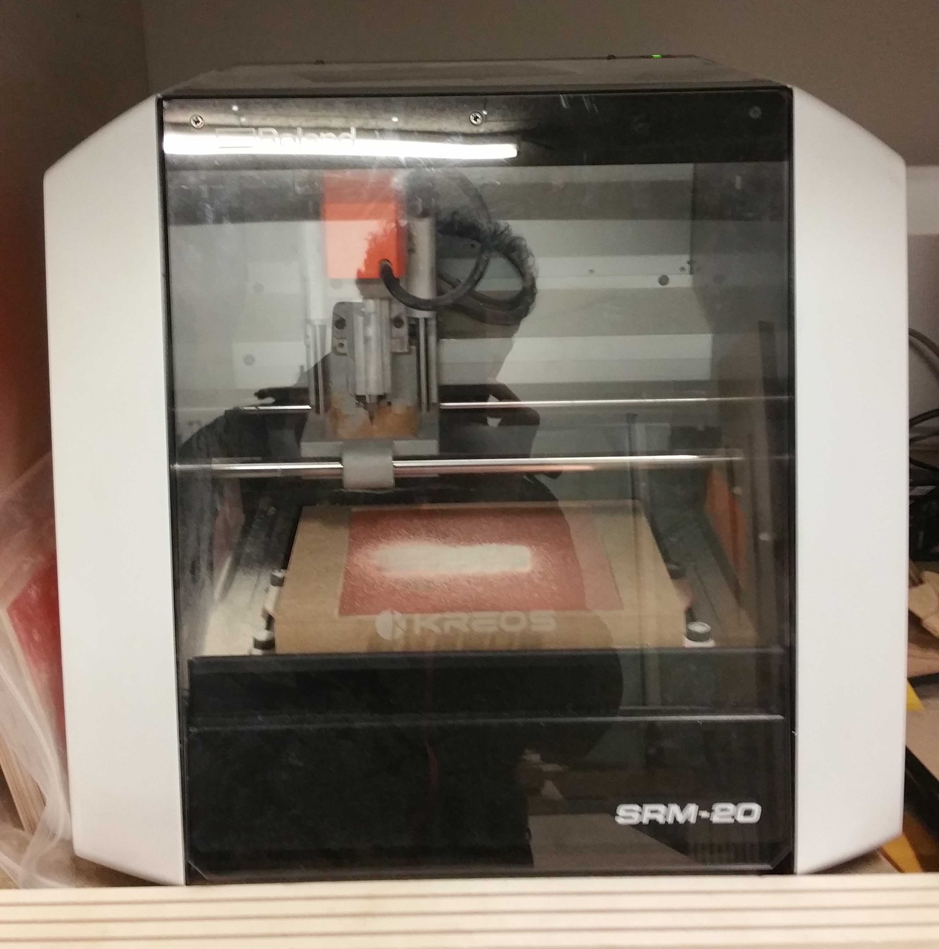
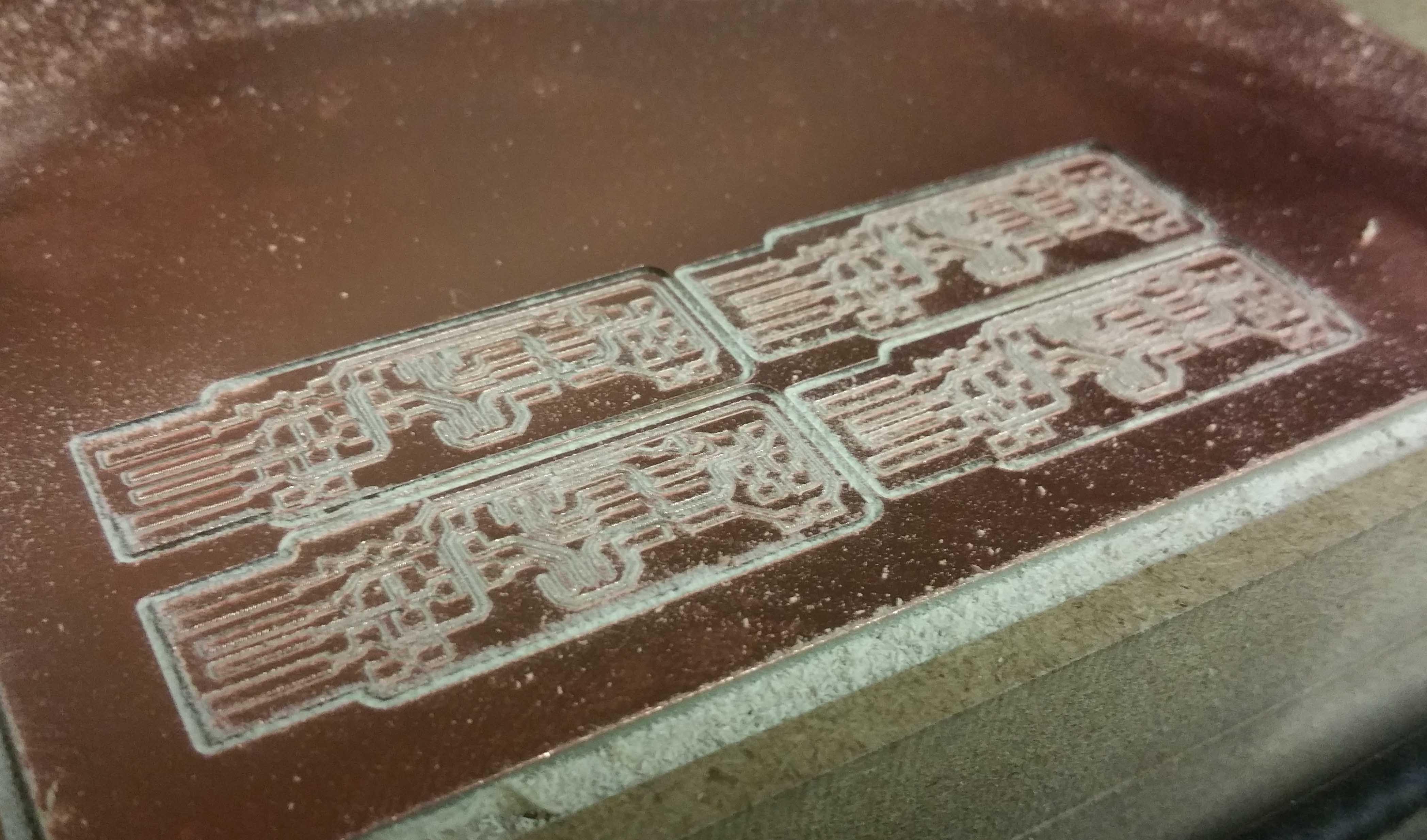
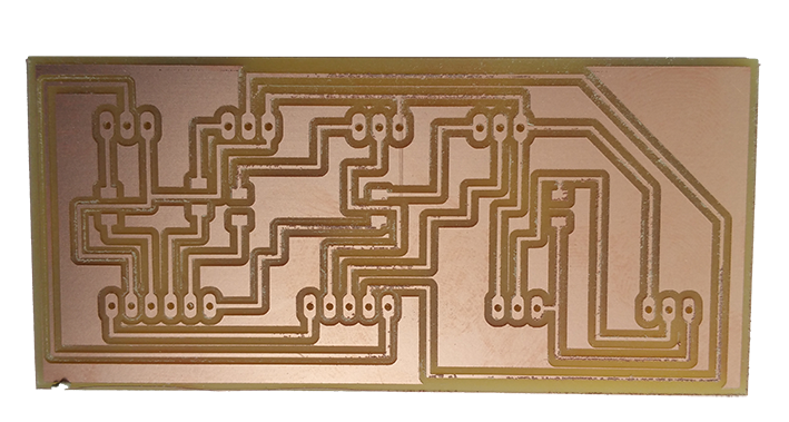
Step 3 : Mill your PCB board with your milling machine
We have a Roland SRM-20 milling machine.
The next picture is the control panel of the milling machine.
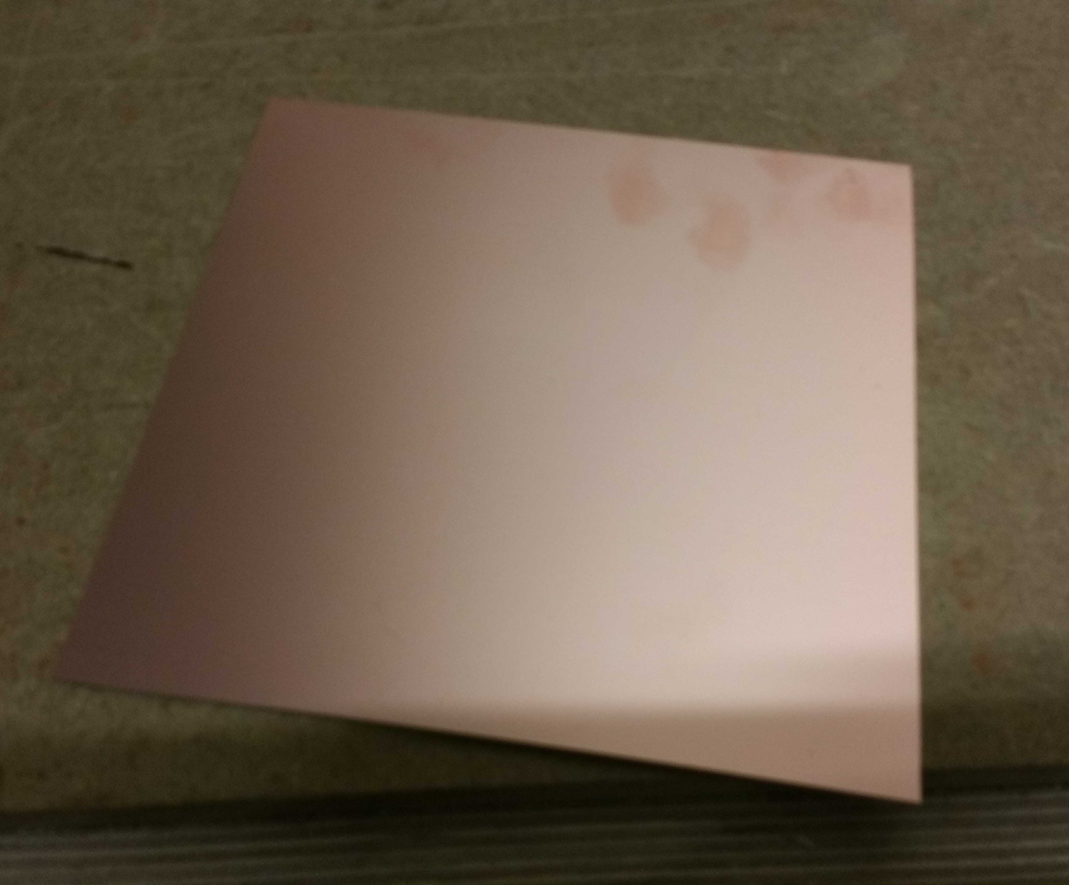
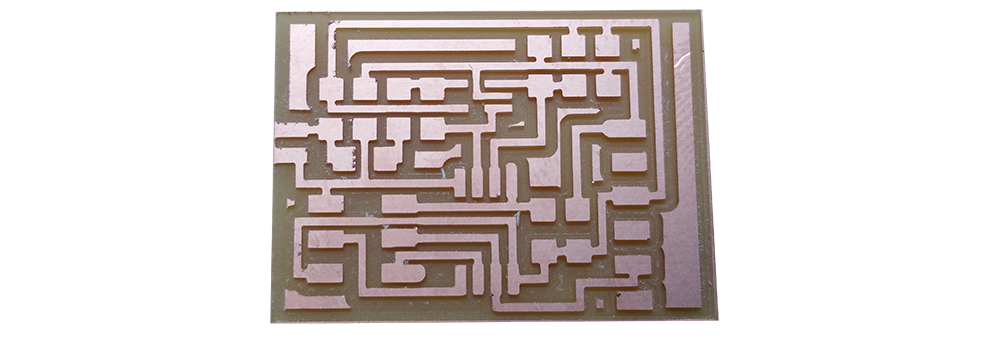
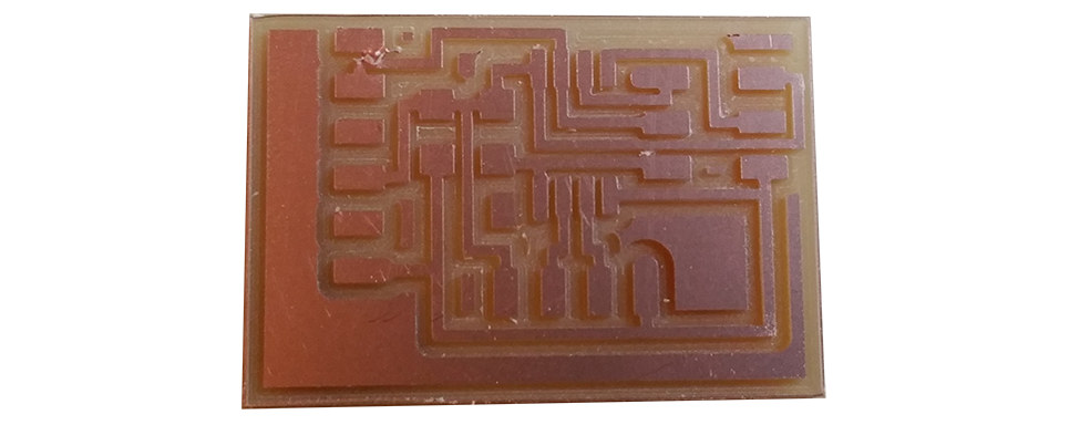
The PCB board before milling.
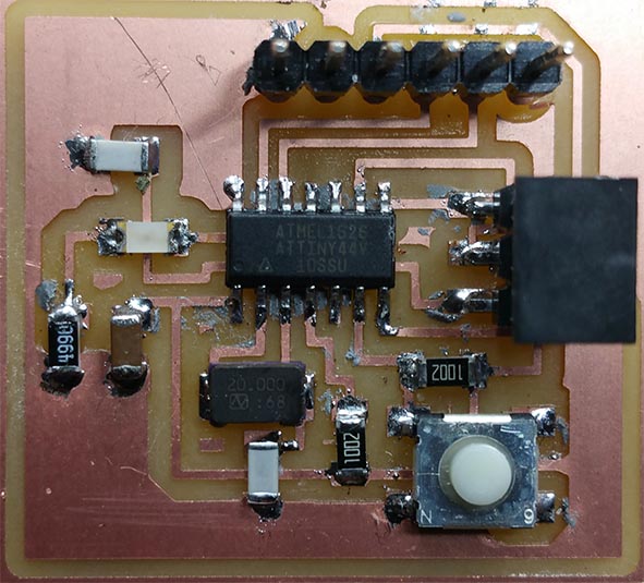
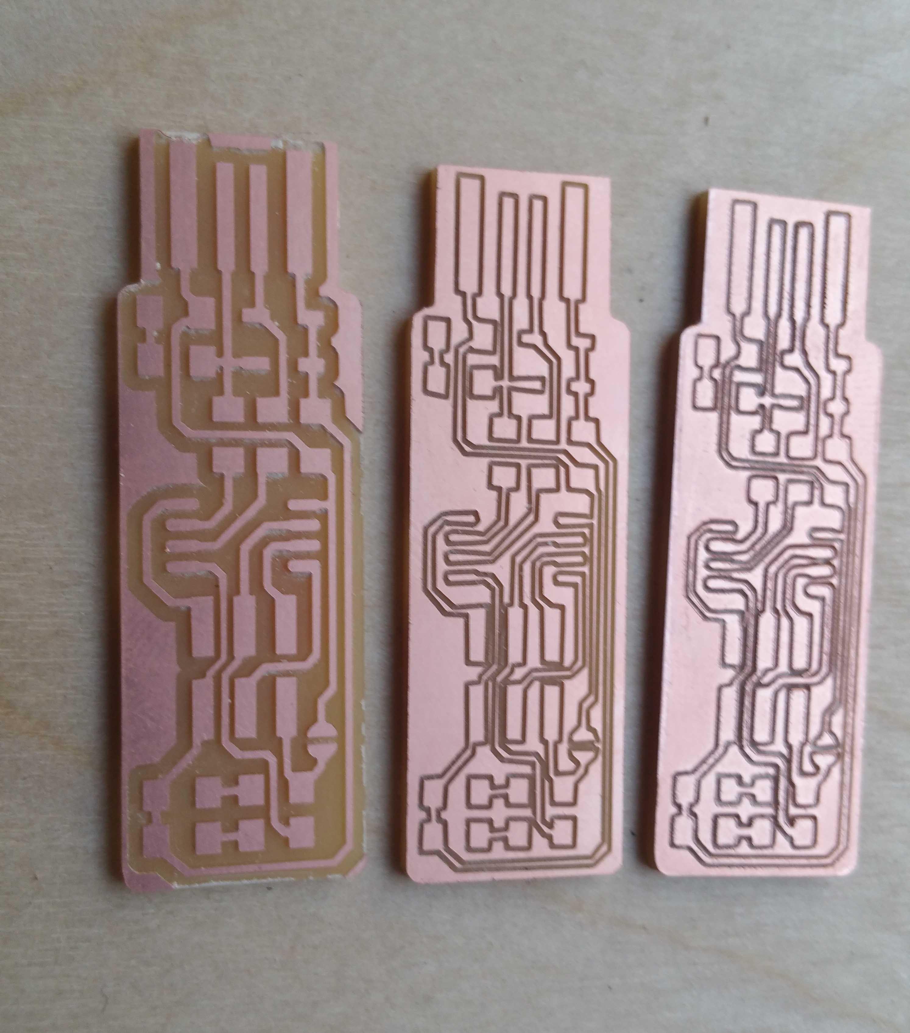
This is the result after milling the trace and the outcut.
This is the result after the third test
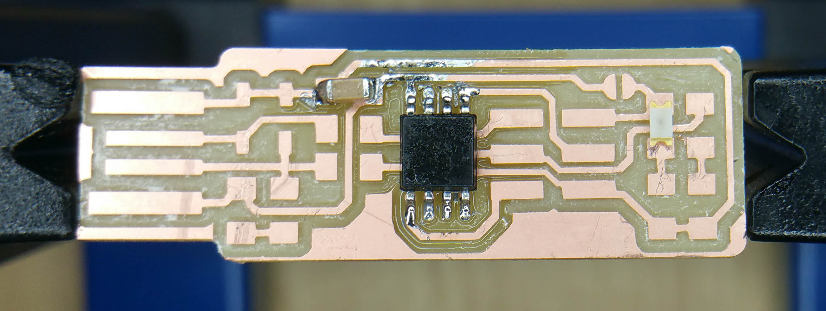
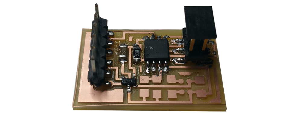
Step 4 : Assembling the PCB and his components
At first we can review all of our components in the box : 1 x ATtiny 45 2 x 1kΩ resistors 2 x 499Ω resistors 2 x 49Ω resistors 2 x 3.3v zener diodes 1 x red LED 1 x green LED 1 x 100nF capacitor 1 x pin header 2x3
I placed my pcb on my pcb holder
I clean my pcb board with isopropyl alcohol
Now we can place the microcontroller ATtiny 45 with my electronic clamp on the pcd Board after clean the board with isopropyl alcohol.
I used the paste to weld to each pins of the microcontroller Attiny 45.
with the soldering iron i heated every pin of the AtTiny 45 to weld them in the same time.
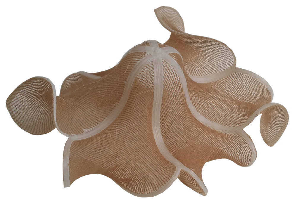
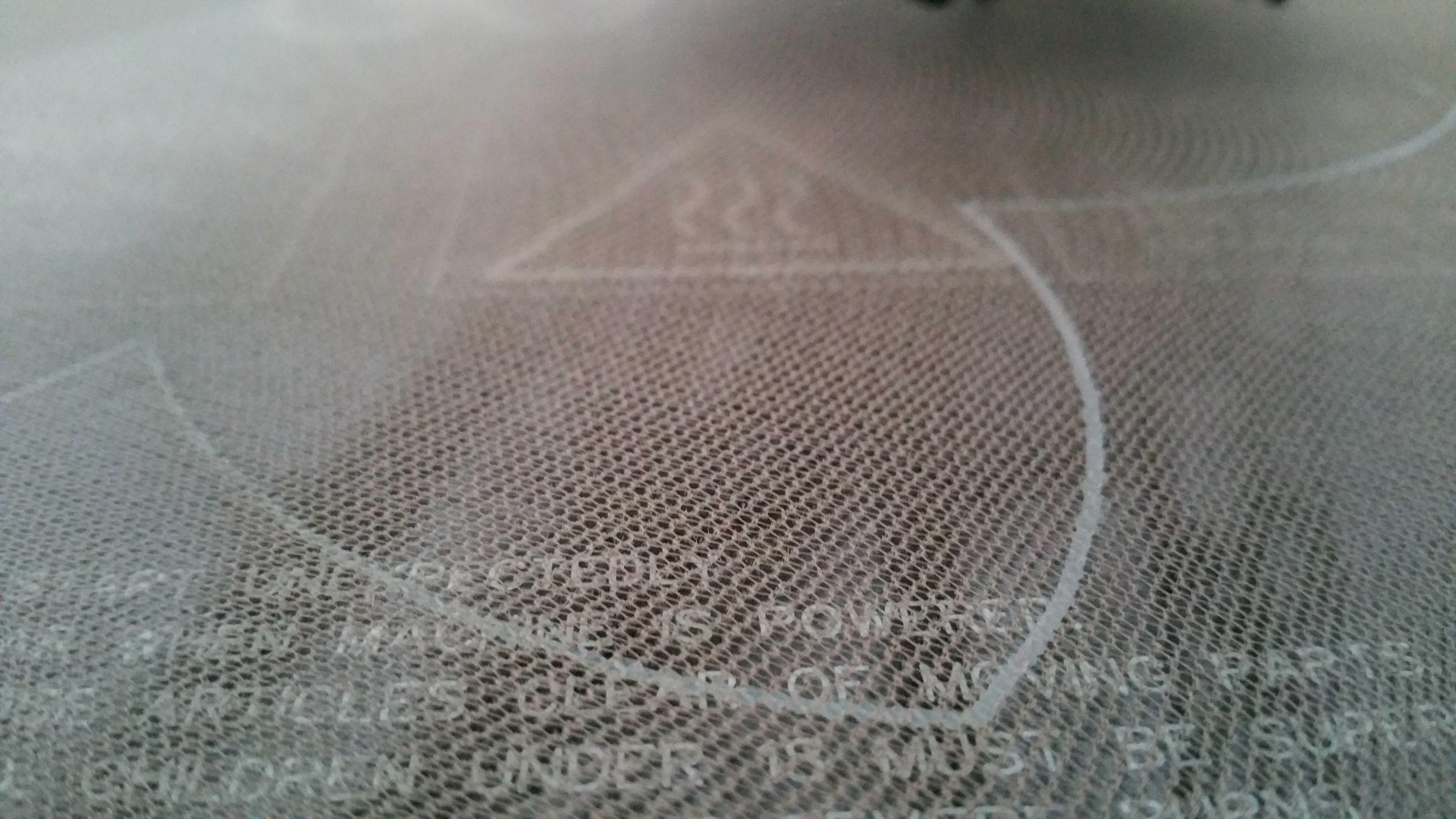
This week we will experiment 3D printing with differents technology as FDM an Stereolitography
We also will try to scan flower with complex geometry and print it
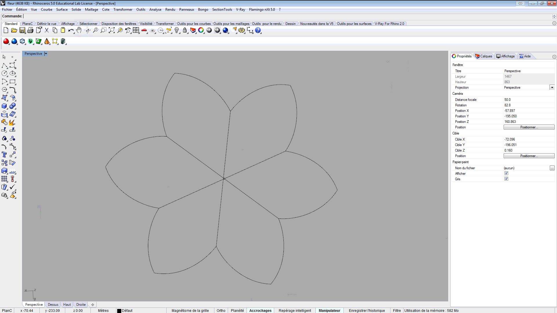
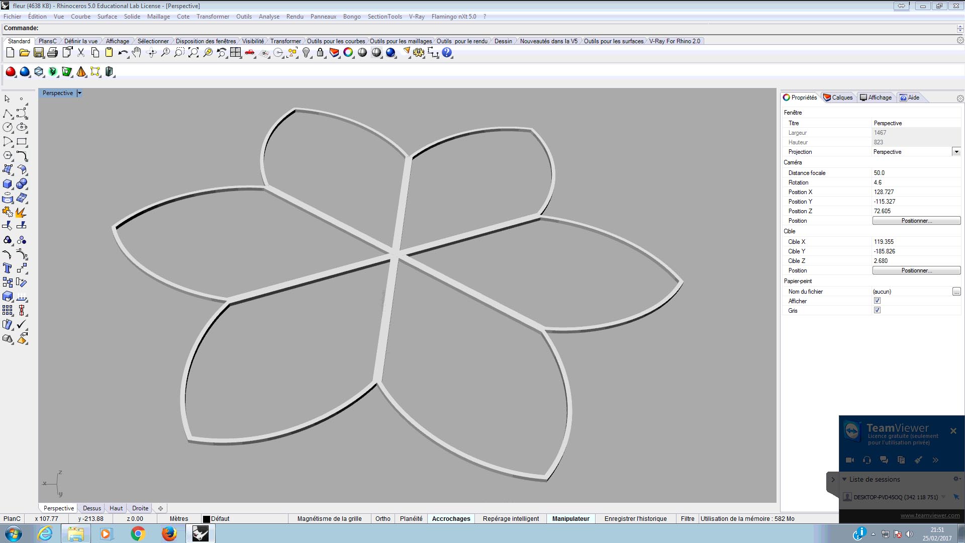
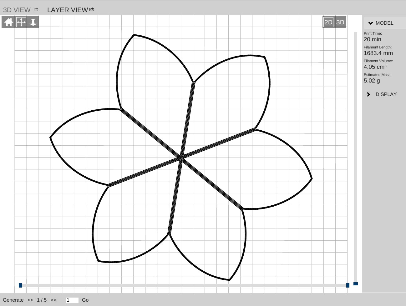
STEP 1 : Draw your pattern in 2D
I used Rhinoceros 3D to design a first pattern that will be folded by the tension inside the tight
STEP 2 : Build a volume to print
I extruded my pattern to build a volume able to print.
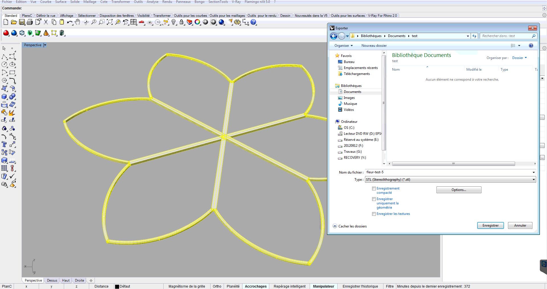
STEP 3 : Export your 3D file in STL
Before printing you need to export the part you want in . stl. So you click on file -> export selected object and save your file.
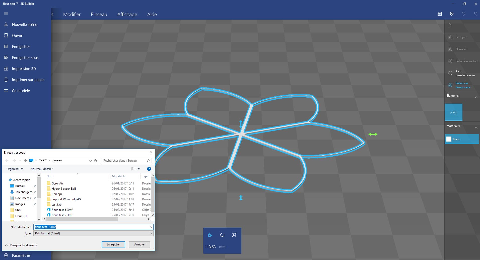
STEP 4 : Prepare your file with 3D builder
You can use 3D builder to check if your .stl is without error.
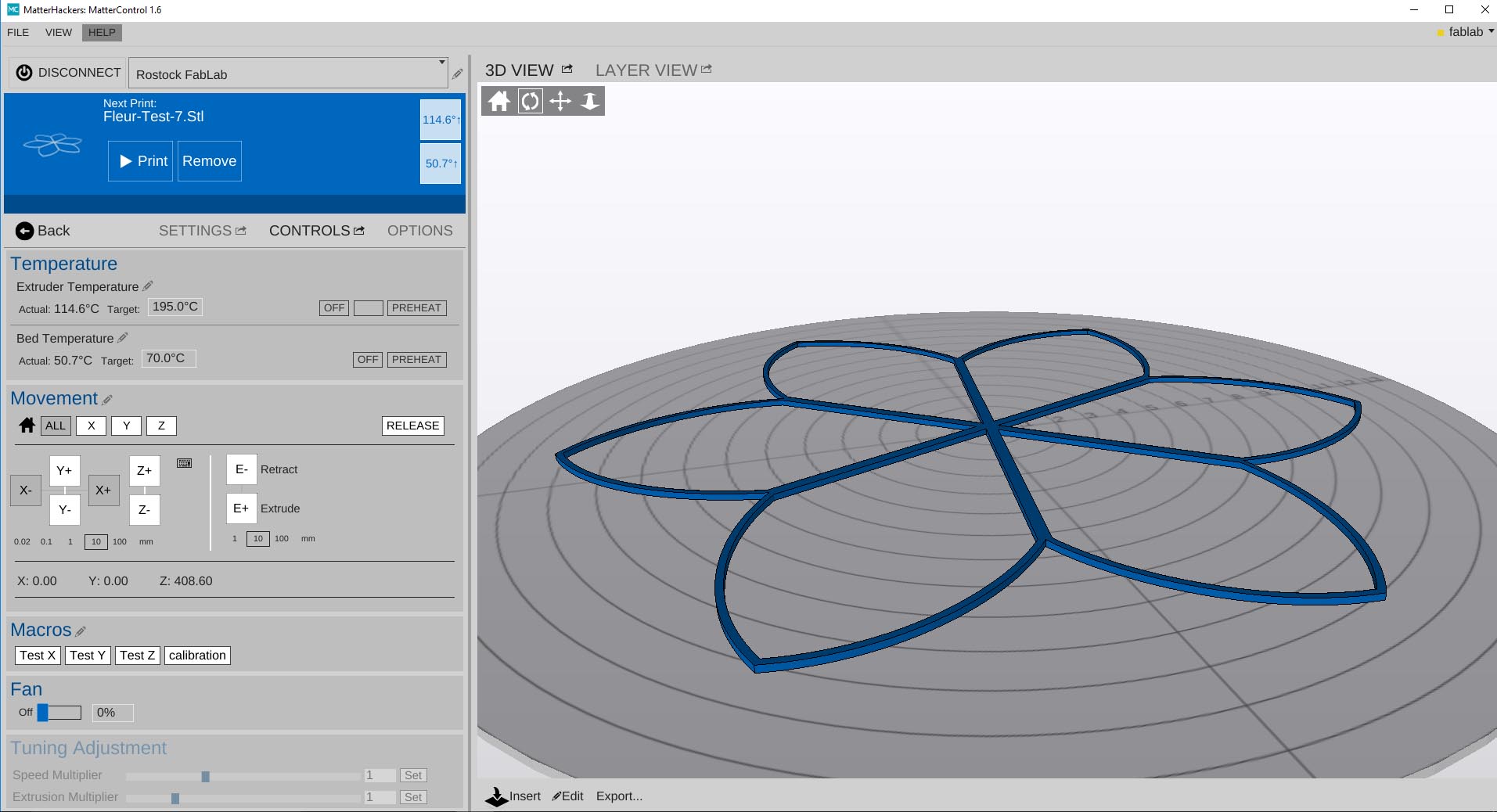
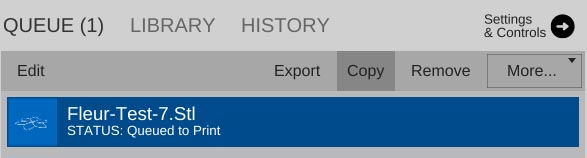
STEP 5 : Open your file with Matter control
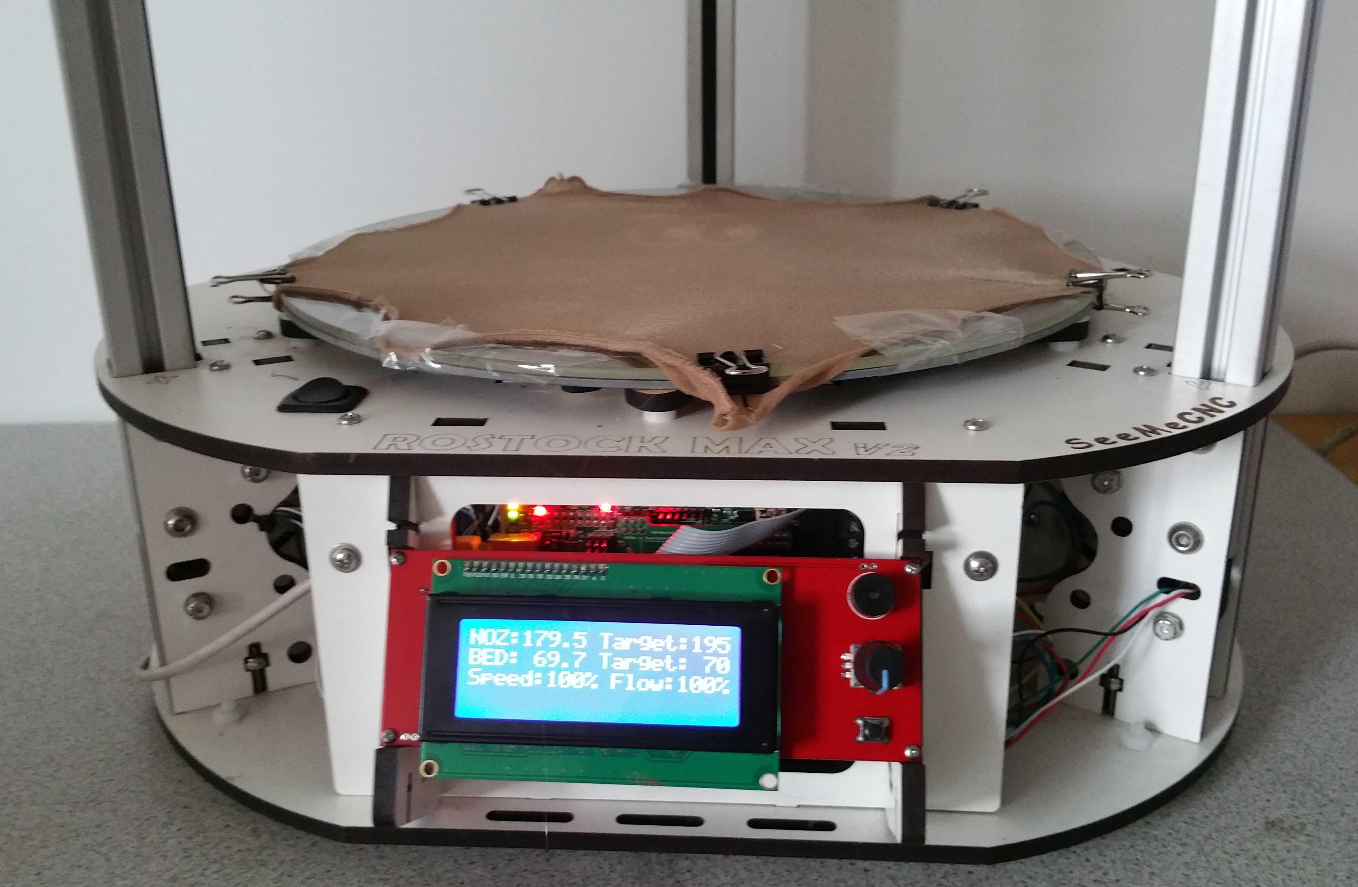
We will use a rostock V2 max, the software corresponding is matter control. It is a free,
opensource software package that let you organize and manage your 3D prints.
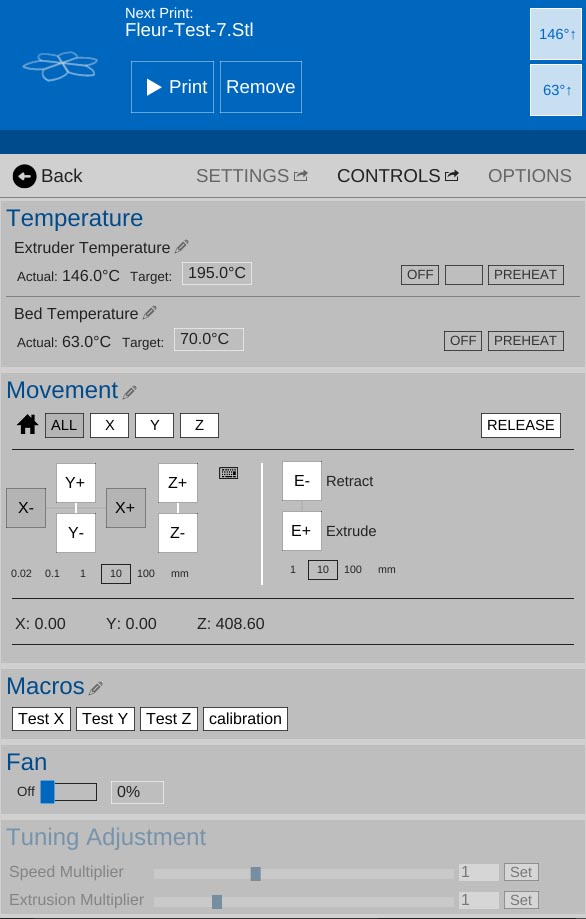
I verified the calibration of the 3D printer
I used a flexible filament whose the temperature of fusion is 195°C, for the temperature of the bed is 70°C.
Now i sliced the model to see the path of the extrudor durint the print.
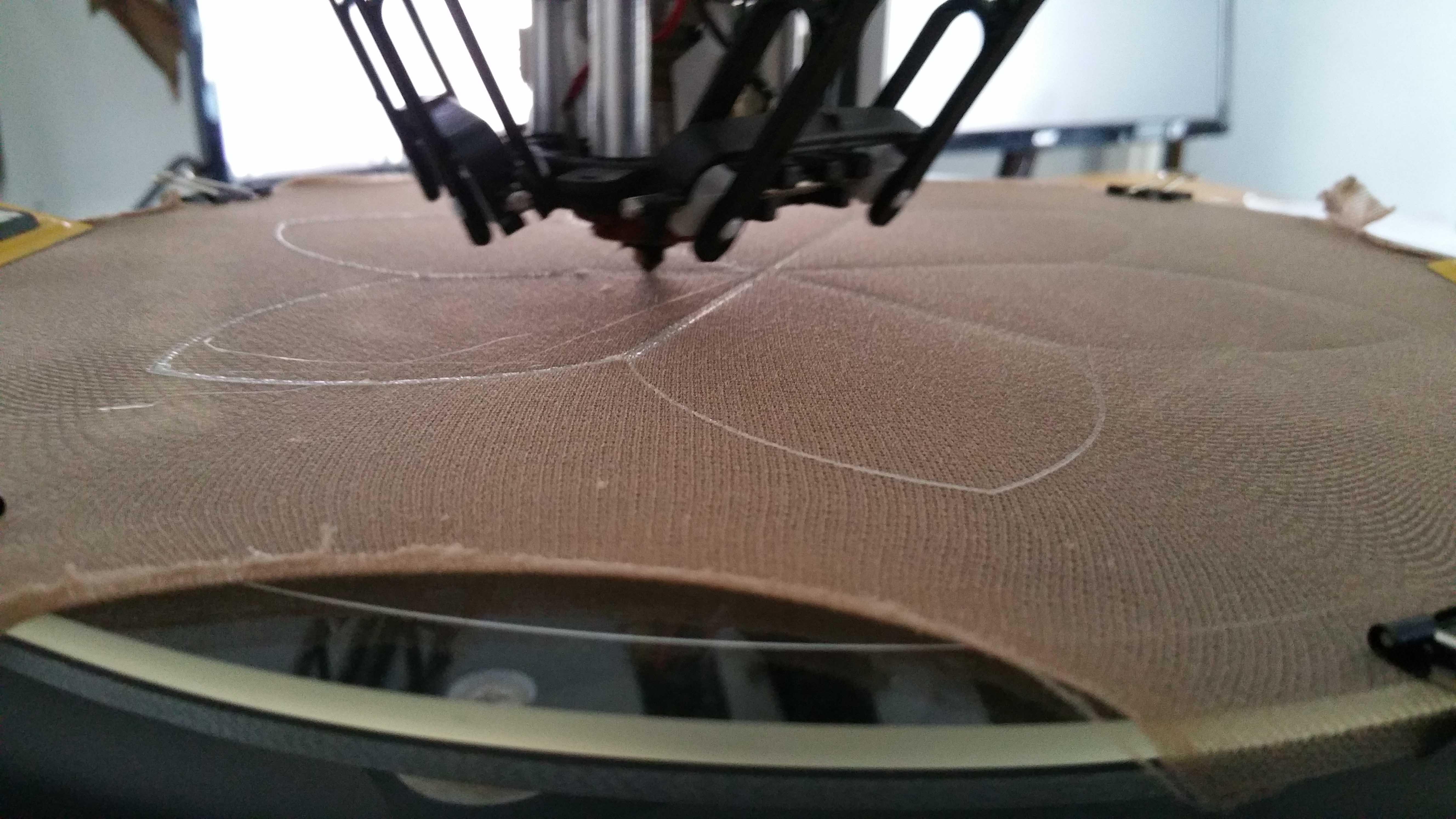
STEP 6 : Prepare the tights on the bed of the 3D printer
I used some clamp to stretch the tight on the bed of the 3D printer
As we can see with the heat the PLA plastic enter inside the tight
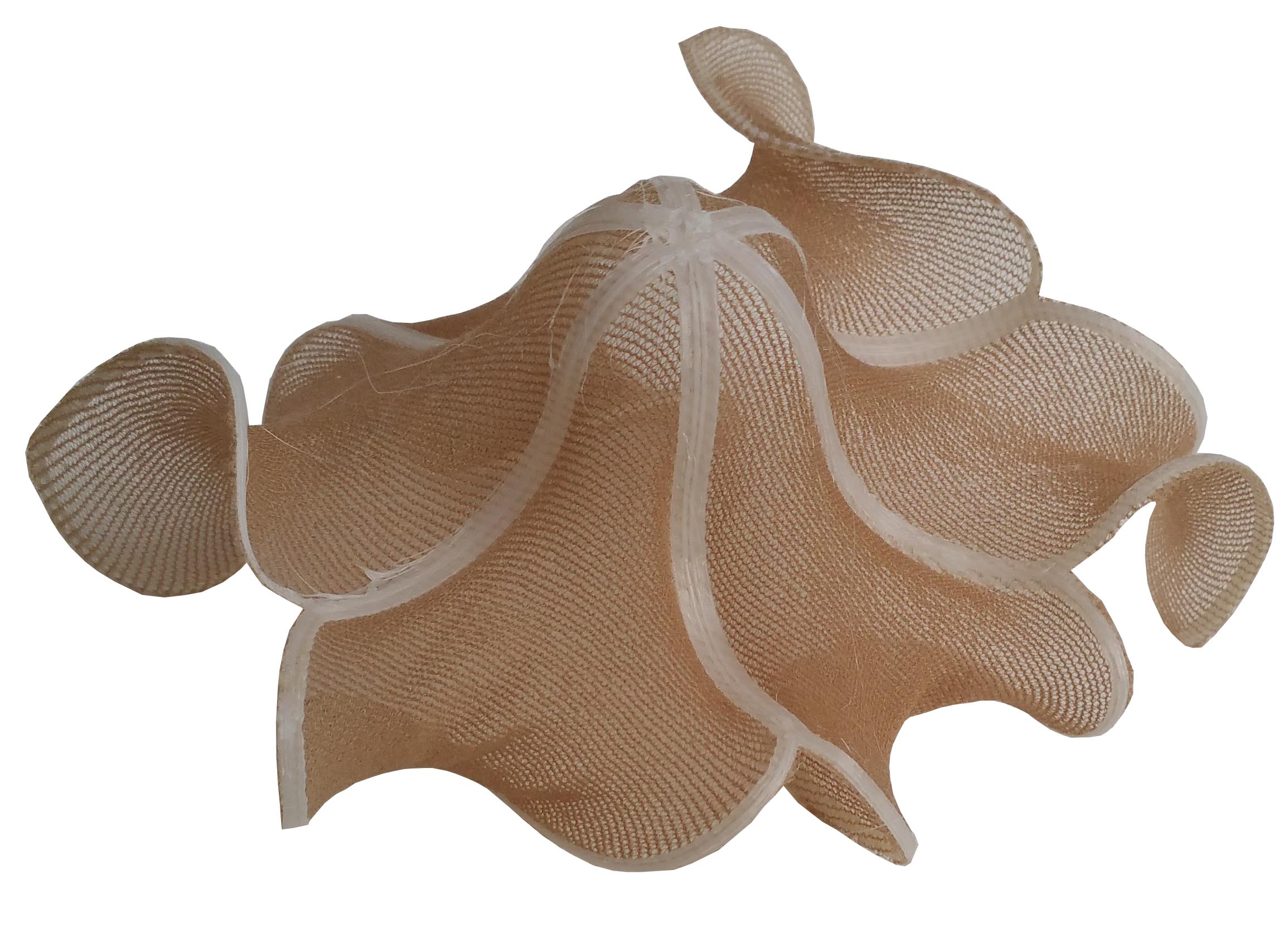
StEP 7 : 3d printing
We can start to 3D print to make the test.
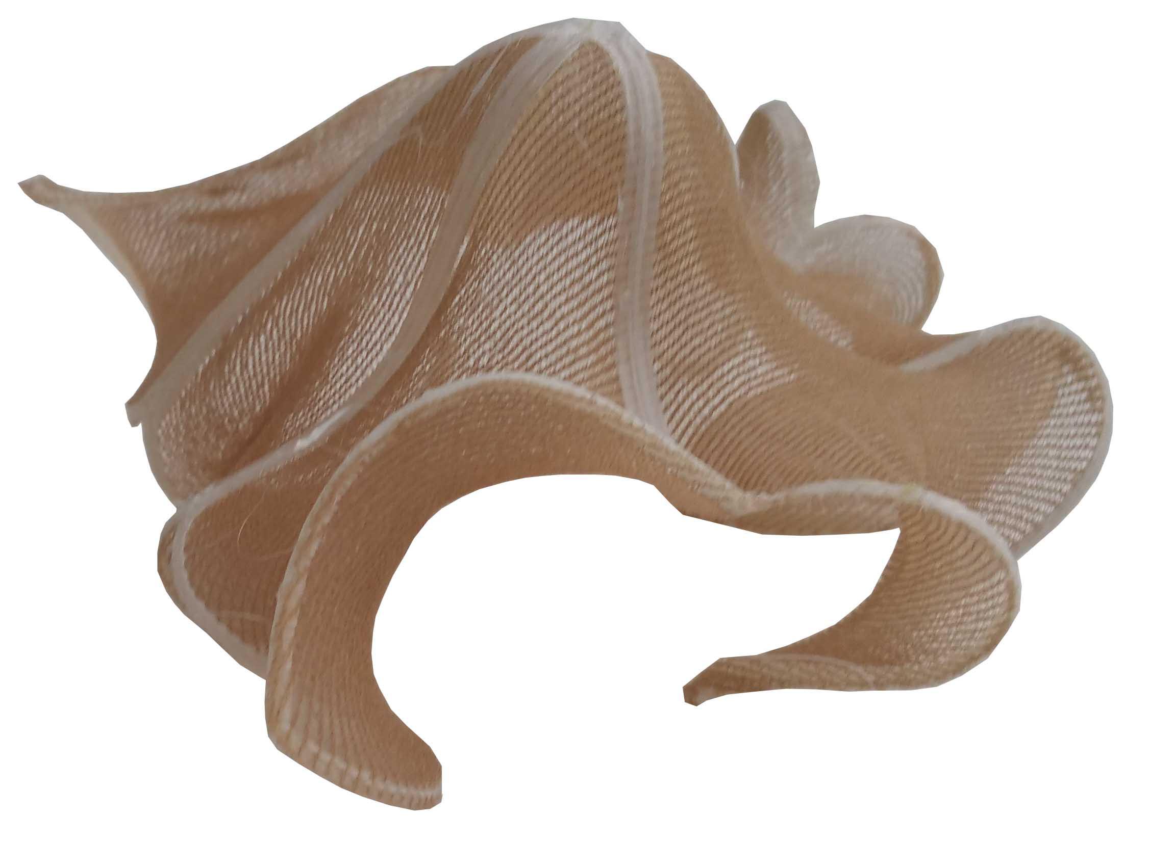
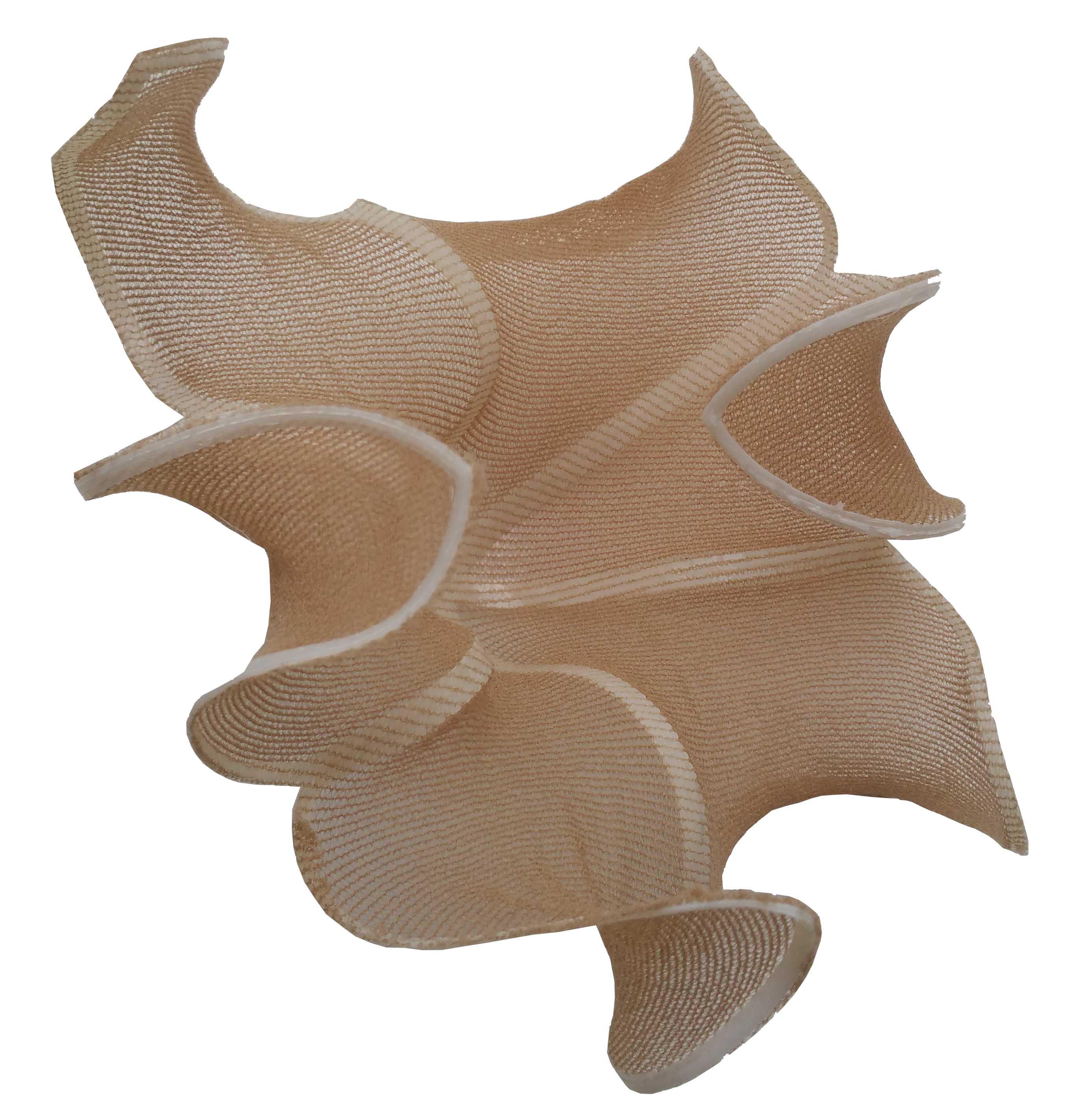
Result
When the print was finish, i cut with a cissors the exterior part of the pattern. Now we can enjoy the funny result.
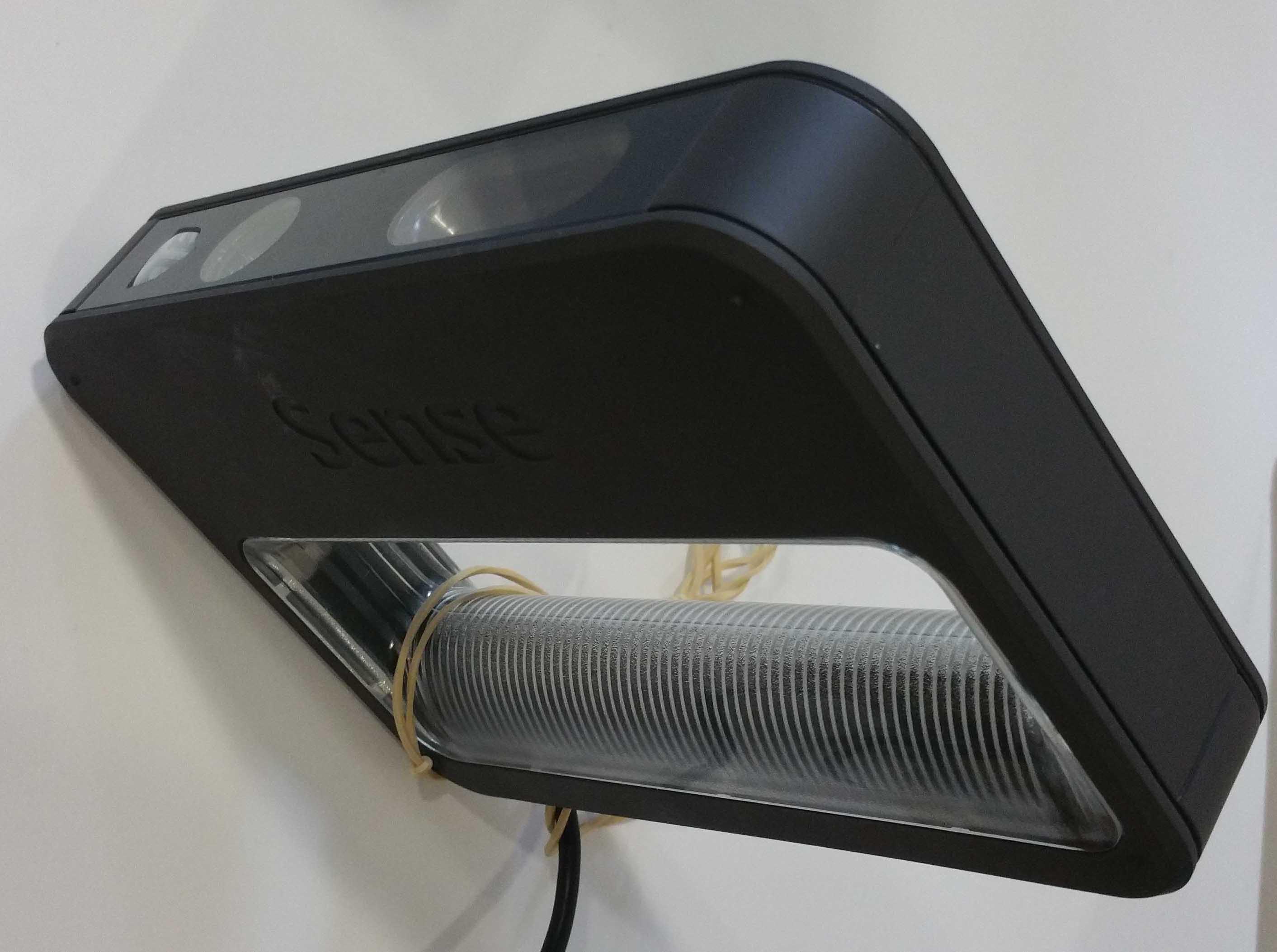
How to scan and print yourself in 3D
STEP 1 : Connect your scanner 3D and launch the software
For this assignment i will use a scanner 3D Sense by 3D system.
STEP 2 : Choose the kind of things that you want scan
When you start the software, you have to choose the kind of object you want scan.
STEP 3 : Start to Scan
I chosse to scan my self. Before lanch the numerisation you have to be at approximatively 40 cm of the scanner 3D.
That's the result of the 3D. This not very precise because it's not a professional tool.
STEP 4 : Repare your 3D
After you can use some tools to finish your 3D model
STEP 5 : Export in .OBJ
Now we will export in .OBJ to open the file with rhino
STEP 6 : Export in .STL
Rhino is very usefull to export in .stl with high quality.
STEP 7 : Open with Preform and set parameters to print
with preform we will set the material and the accuracy of the print.
We can scale the 3D model to choose the size of our object.
STEP 8 : Generate supports to print
Now we click on generate to generate supports. That the final 3D that we will be print.
We send the file to the 3D printer with the right material.
This is a Stereolithography 3D printer named Form 2.
Result after printing
The 3D printed object was extruded by the platform from the liquid resin.
Finishing the 3d printed object
Now we need to place our object inside a alcohol bath and cut the support to have the final object.
Result after finish
This is the final result. The accuraccy is not wonderfull. Bur we can reconize something.
Identify advantage and limitation of 3D printing technology
There are different additive manufacturing technologies. The 3D printing has material deposit, called FDM technology. FDM works on an "additive" principle by laying down material in layers. These 3D printers are the most common in Fablabs.
The materials most often used are plastics of the PLA and AB type which have the particularity of having relatively low melting temperatures in the range of 170 to 240 ° C. More and more, there are biobased materials (algae, coconut, hemp etc.) that are most often mixtures of 70% plastic and 30% bio-sourced material.
The common problem with this type of printer is the extrusion speed and the surface appearance of the parts produced.
The different volumes of printing on 3D printing machines are most often of the order of magnitude of 20x20x20cm.
More and more these machines are perfecting and sometimes offer extruders with two extrusion nozzles thus making it possible to produce multi-material prints or with soluble supports that allow for overhangs, but also require more post-processing
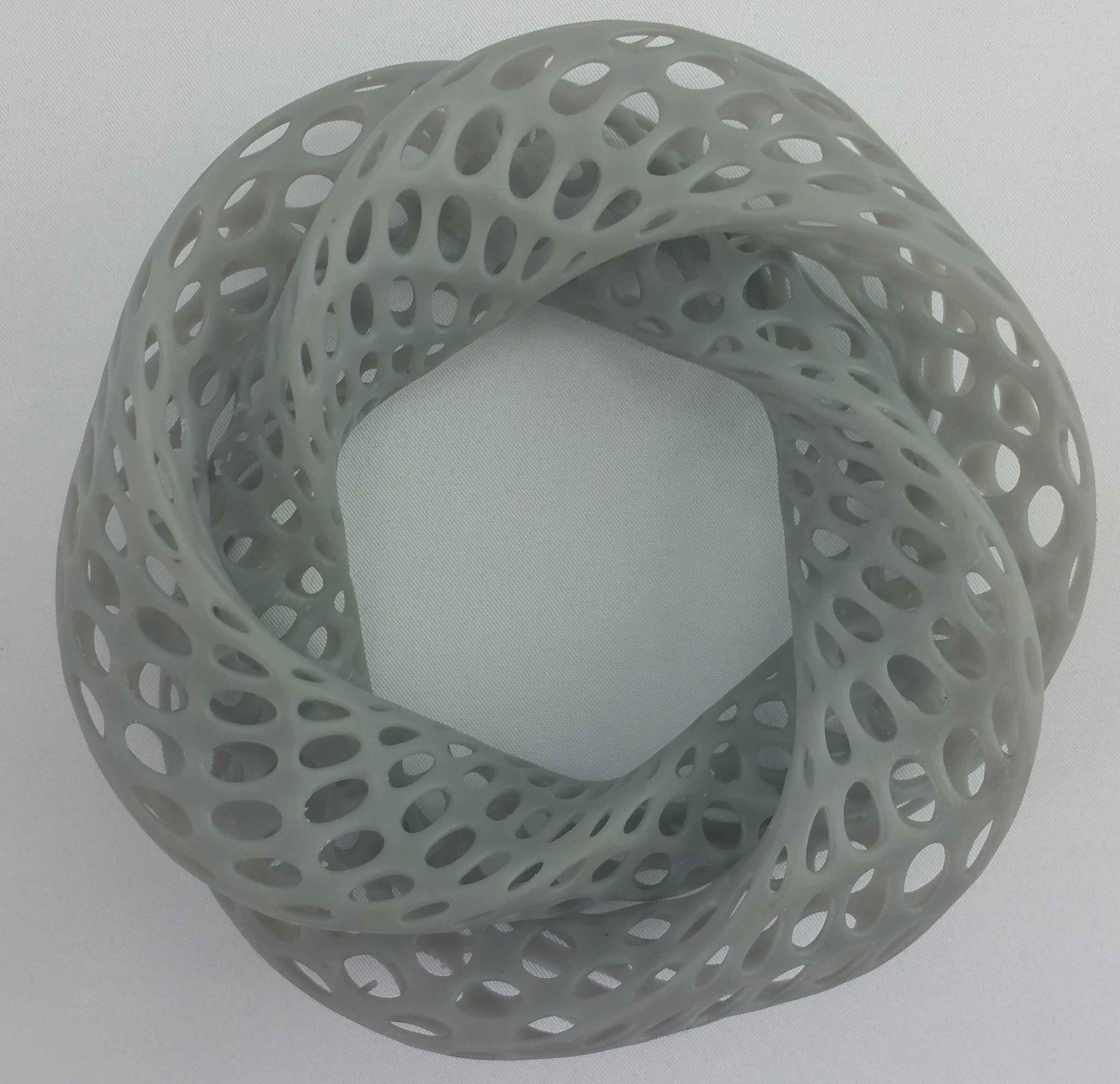
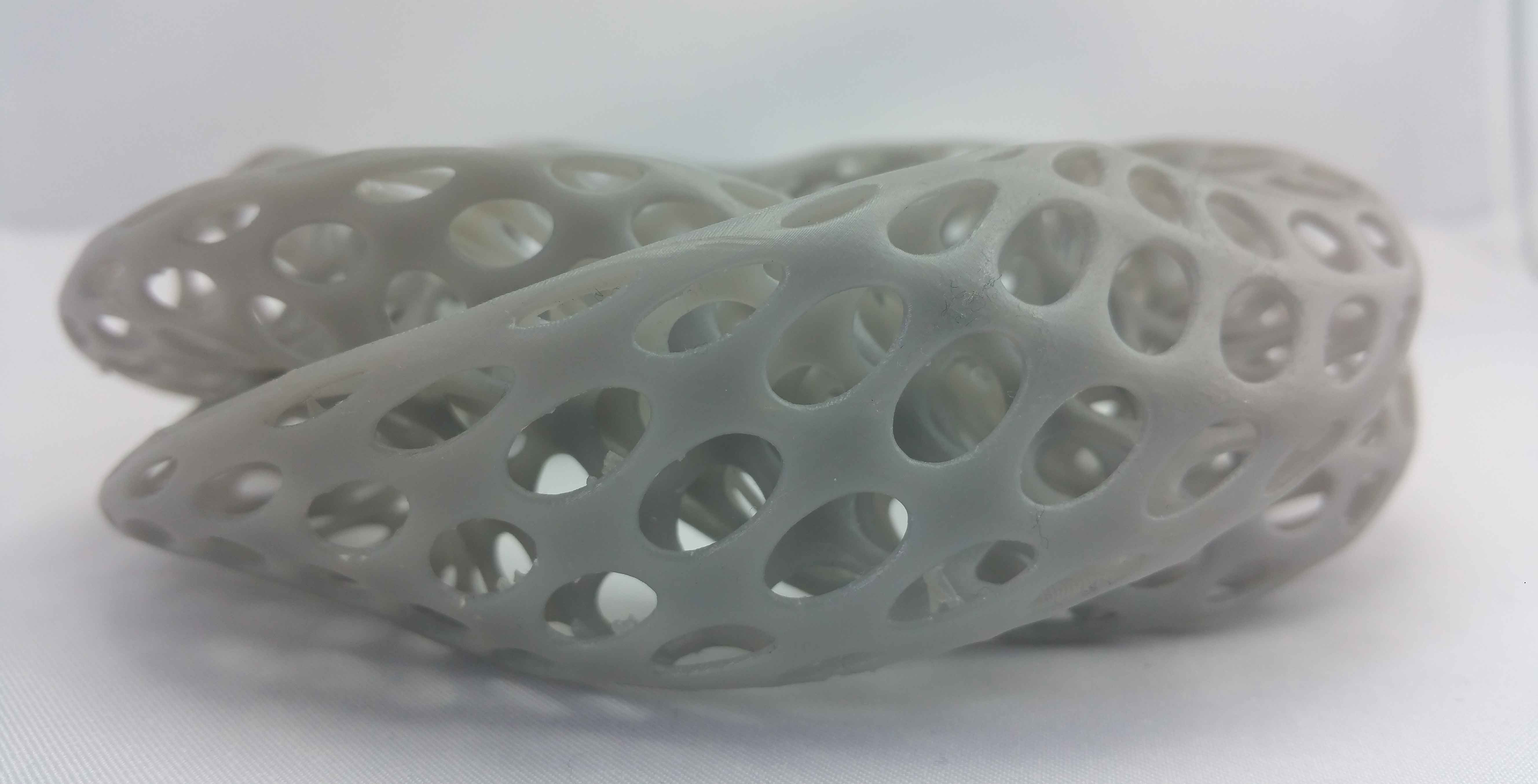
However, there are emerging technologies such as SLA desktop 3D printers (Stereolithography) that use the principle of light curing to make 3D models from a UV-sensitive resin. This is solidified by the passage of a laser layer after layer. It provides one of the most qualitative printing surfaces of existing printing technologies.
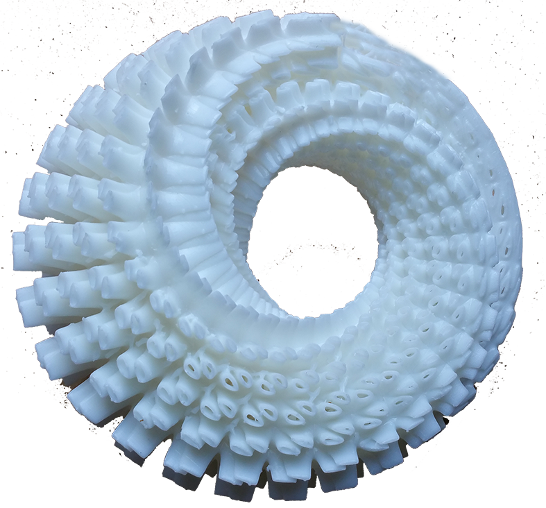
In this case I used a FORM2 to make the following pieces. I try to achieve the finest 3D printing possible to go to the limit of possibility of manufacturing this SLA technology. Using visual 3D programming software, in my case, the Rhinos / grasshopper software. The pieces have been printed with supports that are generated by the FORM2 printing software. Then in a post-processing operation, she was separated from these supports. Then as a finishing, the piece was placed in a 90 degree alcohol bath to dissolve the resin remained stuck on the surface during extrusion and to improve the surface condition of the piece
Design and print 3D objects
Make your echo hello-world board
With Eagle, a pcb board, a cnc milling machine and some cms components.
This week we will try to design our own electronic design wit Eagle. We will begin to open eagle and draw the schematic
of the board and export a png file of the board. Then generate the g-code to mil the board.
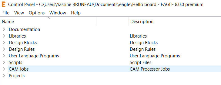
Step 1 : Open Eagle
Eagle is a CAD software to electronic design. You can simulate your circuit before make it.
At first you need to have an Autodesk ID to open Eagle. When you open the software you have the control panel.
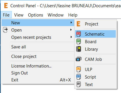
If you want draw your circuit you can click on file > New > Schematic. You have this window :
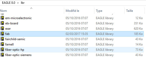
Step 2 : Download your libraries component
In this example, I will use the fablibraries downloaded on the fabacademy website.
The file is named fab.lbr. I will save this file with the other .lbr file inside Eagle installation folder.
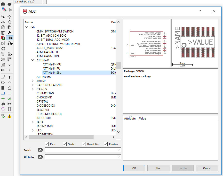
Step 3 : Add the component that you need to make the circuit
Before make your circuit you need add component in the canevas.
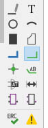
In order to do this you have to understand the main commands of the eagle toolbar.
The first command we will use is the command to add component. You click on this icon (in blue on the picture).
Inside the window named ADD you select your libraries, and you click on the component that you want to add to your future circuit.
In this example we will add a microcontroller named ATtiny 45 SSU.
Step 4 : Connect them together
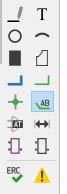
In order to connect your component together you need click on this icon inside the toolbar (net) to make a wire between two pins.
You can name the wire using this icon :
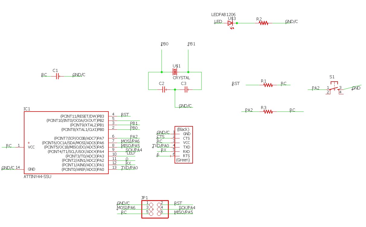
Finally you added all the component you need and you connect them together to make the schematic of your circuit.
Step 5 : Draw your circuit
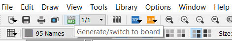
When you finished the circuit you can transform the schematic into board to design your pcb board. In order to do this, click on this icon :
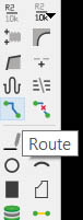
To draw the traces between component you have to click on this icon :
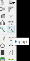
To remove wrong traces you have to click on this icon :
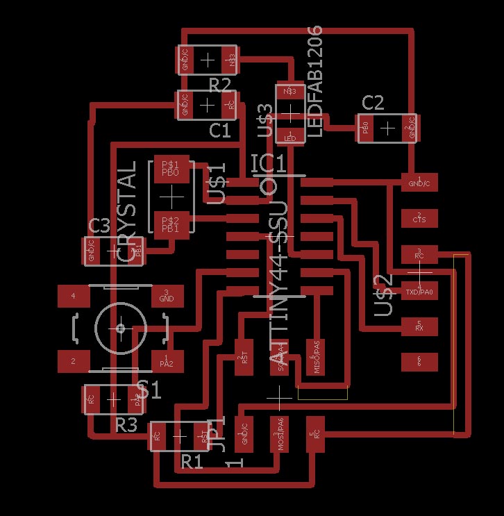
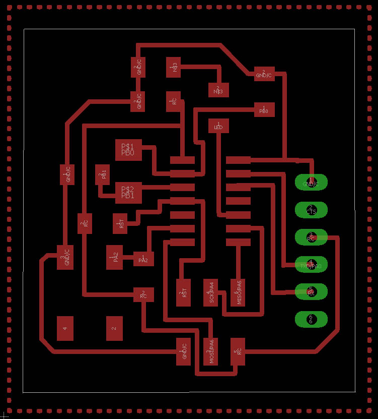
Finally you get a board like this:
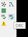
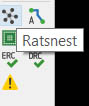
You can verify and check the design rules when you click here:
If it is all right, you can make the GND as a ratsnest
To do this you have to click here :
It gives you this result:
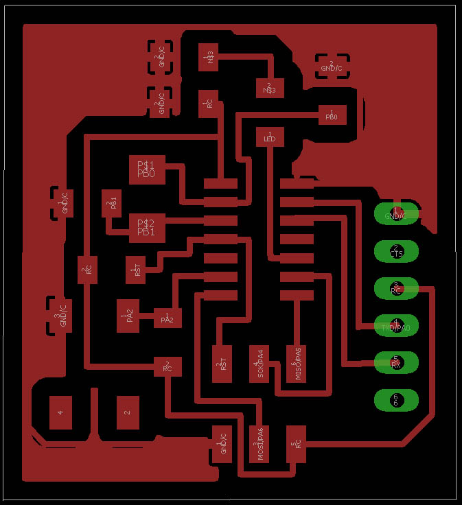
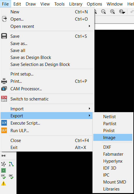
Step 6 : Export the image of your pcb
So you have finished to design your circuit, now you are ready to export your file to mill your PCB board as a PNG image with 1000 dpi resolution monochrome.
Now you hide few layers to export the outlines of your board
Same job for the outlines.
Step 7 : Use Fabmodule
We will use fabmodule to generate the g-code to mill our PCB board.
This is the path to mill our pcb board, and we do the same with the outlines.
Step 8 : Mill your circuit and solder the component
To finish we soldered every component as the schematic/board inside Eagle.We got this result.
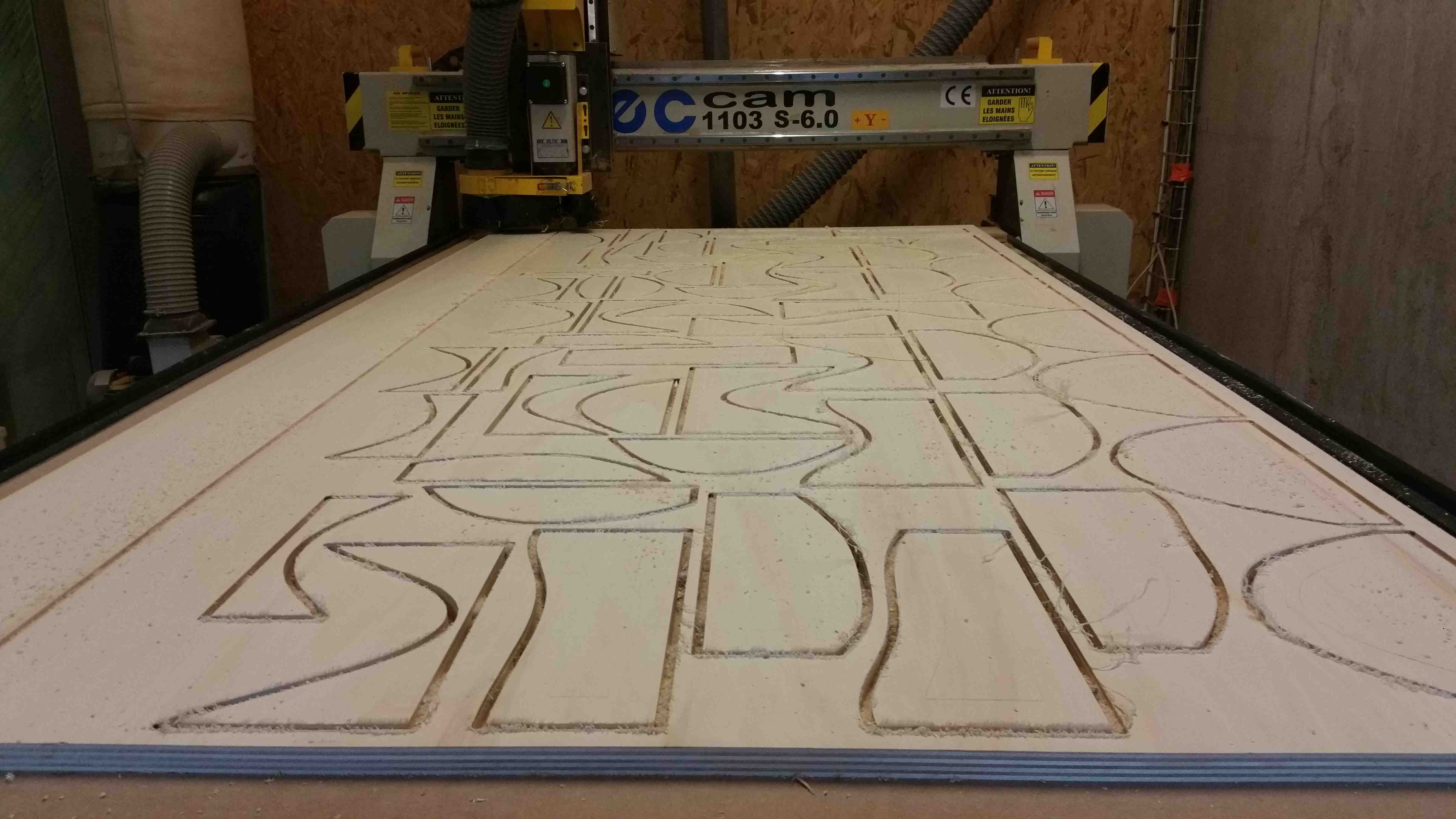
Make something cnc milled
With Rhinoceros , grasshopper and v-Carve pro
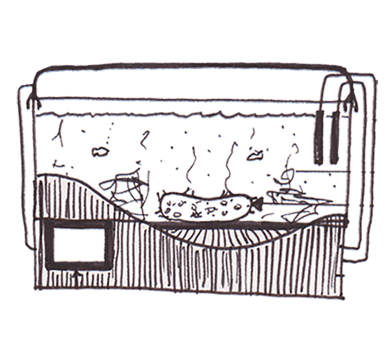
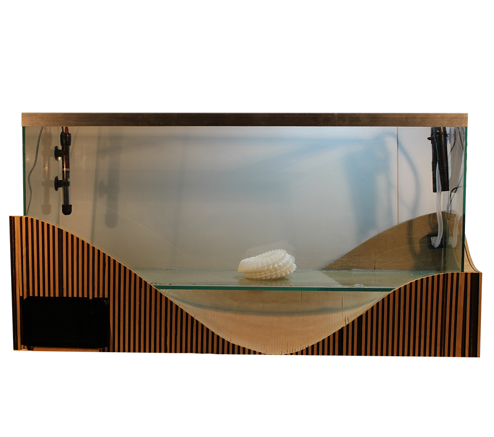
This week we will try to design something big with a cnc milling machine. We will start with rhino / grasshopper to design
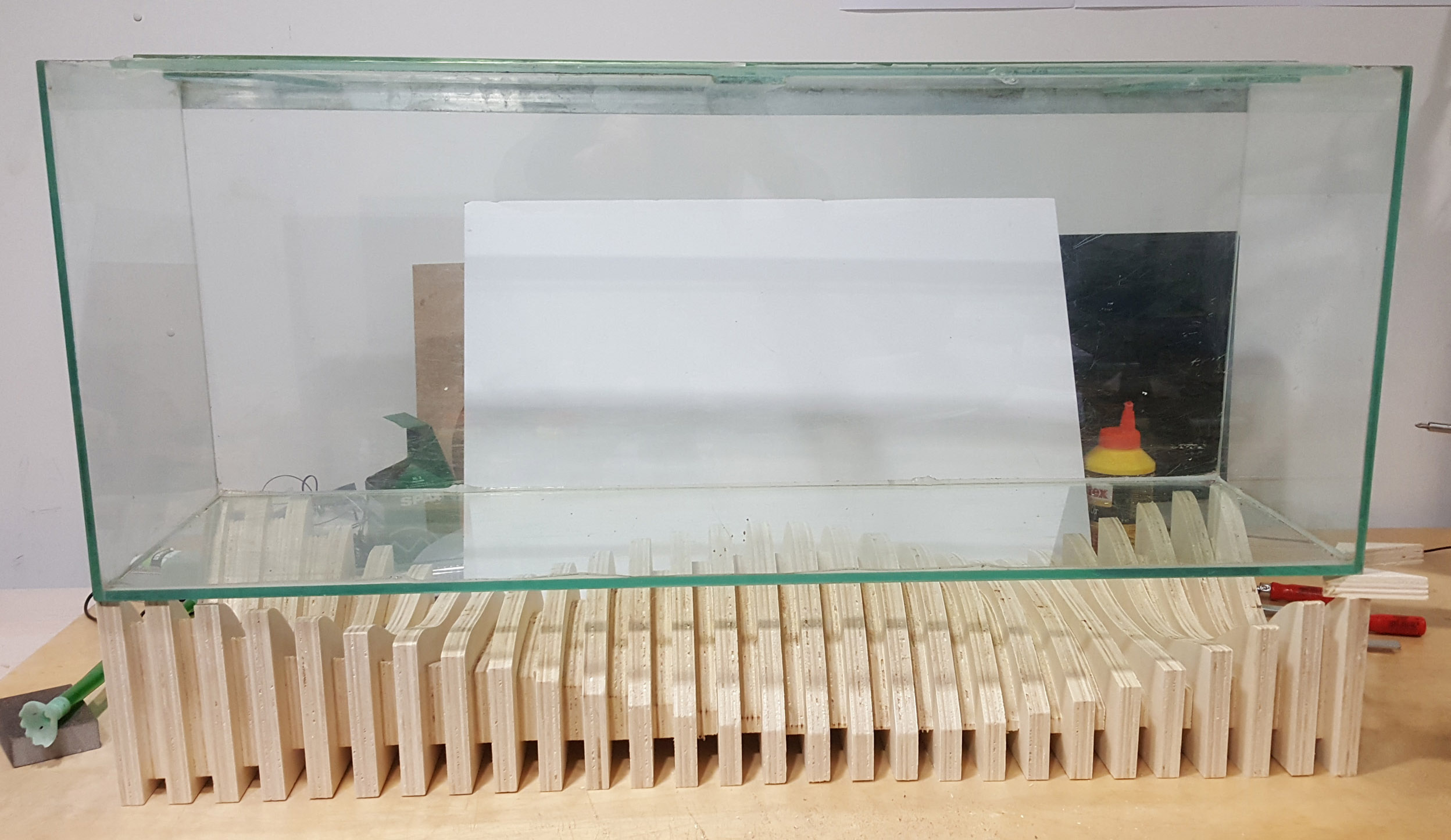
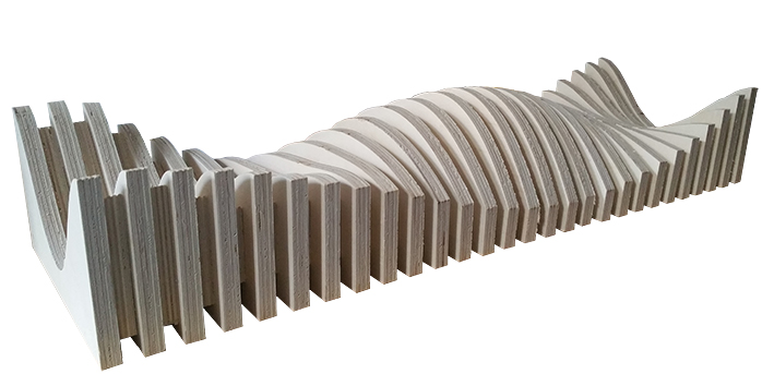
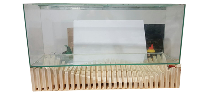
something cool and learn how use a cnc machine. I decided to mill something for my final project. Then i opted for making an aquarium support. Let's go !
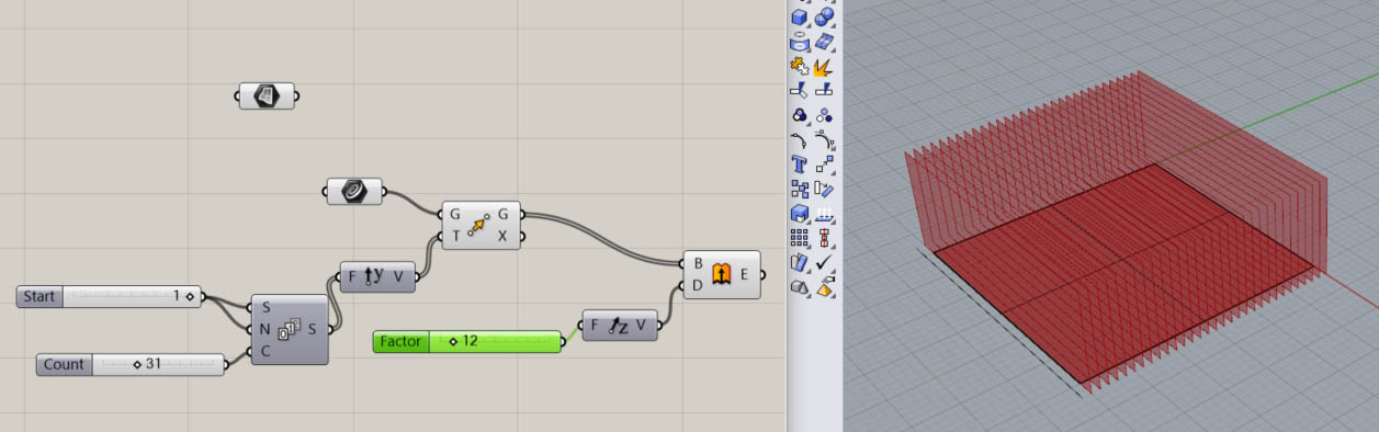
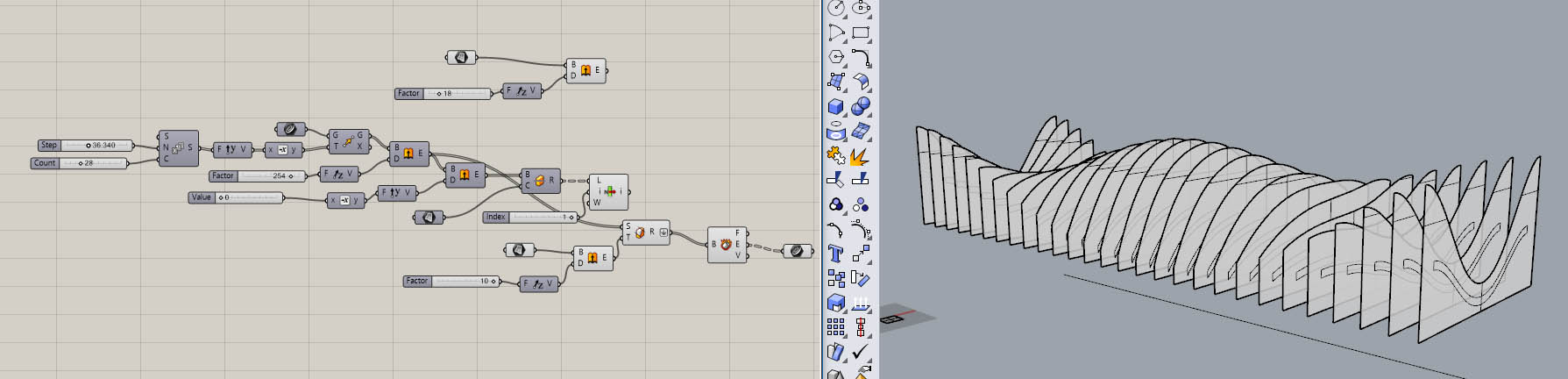
Step 1 : Generate a serie of cutting surface
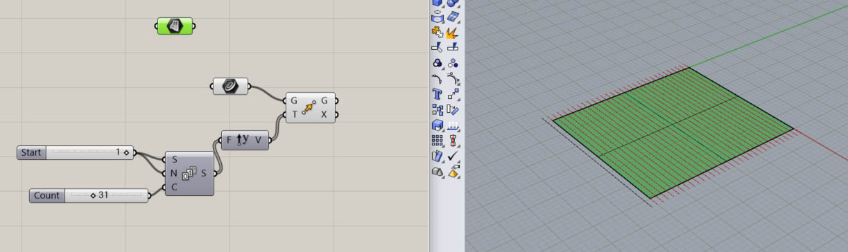
I want to make a biomimetic design to hold my aquarium. To make this by a simple way, i need generate a serie of plane. I draw a curve in hino
and i set my curve inside grasshopper. With a box move, and a box serie i can generate a serie of 31 curve in Y direction with a step of 1 unit.
I extrude all mu curves in Z direction to generate cutter plans.
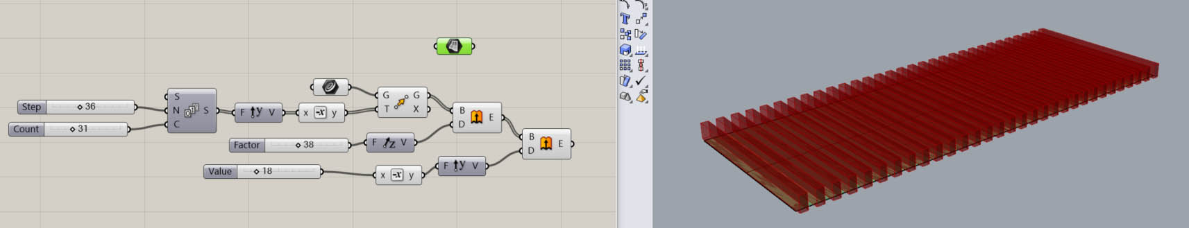
Step 2 : Give a volume to your surfaces
To have a volume to mill, need to extrude all my plans in y direction with a distance of18mm as the with of the wood plate we have.
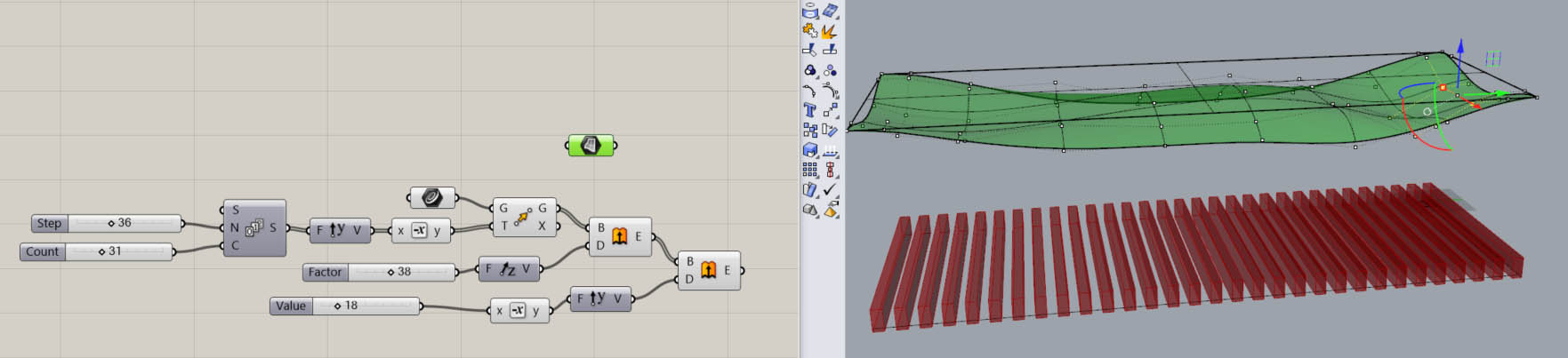
Step 3 : Design a smooth nurbs surface
In order to give some curvature we will try to design a nurbs surface to ha a smooth result.
Step 4 : Cut your volumes with this nurbs surface
We will use our smooth surface to cut all the surface and give a beautiful sinusoïdal continuity to them.
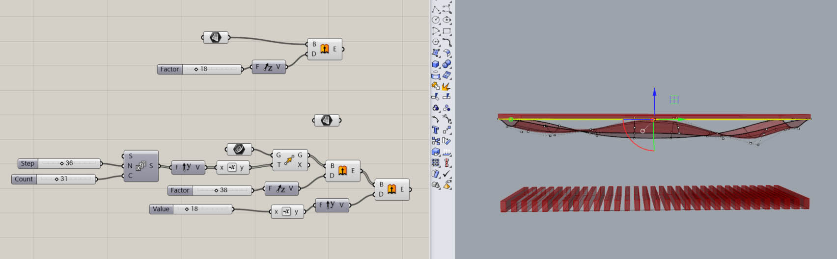
You can name the wire using this icon :
We can see on this picture, the shape we have and how the plate be holded on this support.
Step 5 : Design the connection structure between the volumes generated
I modelise the plate holded on the structure.
I extract the connection between the different part of the object.
Now i extract the curve that i need to mill with the machine.
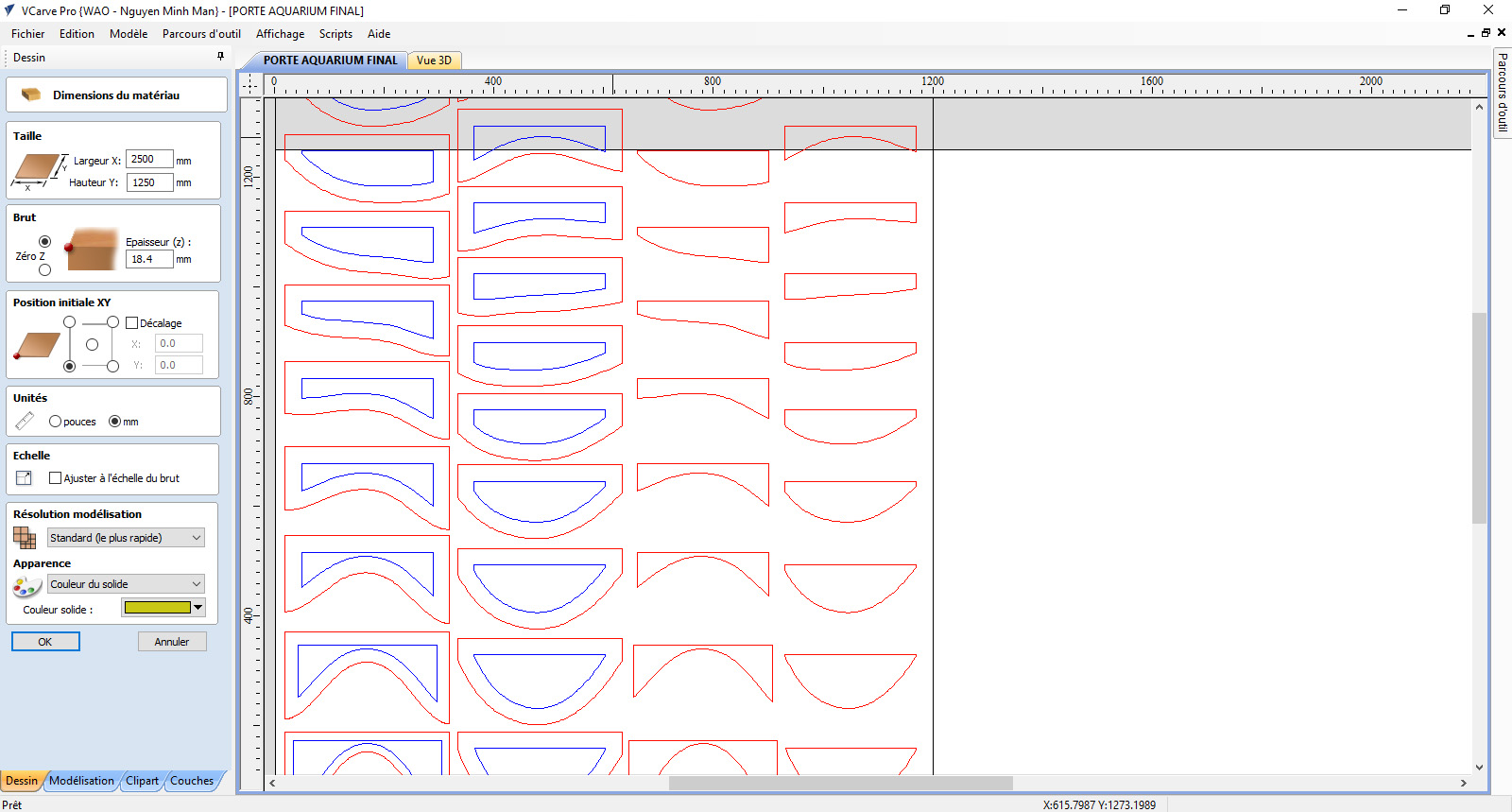
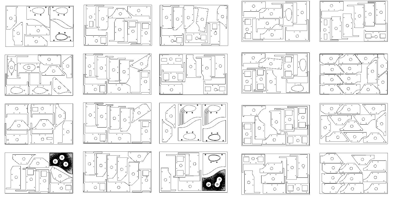
Step 6 : Prepare the file to export in DXF
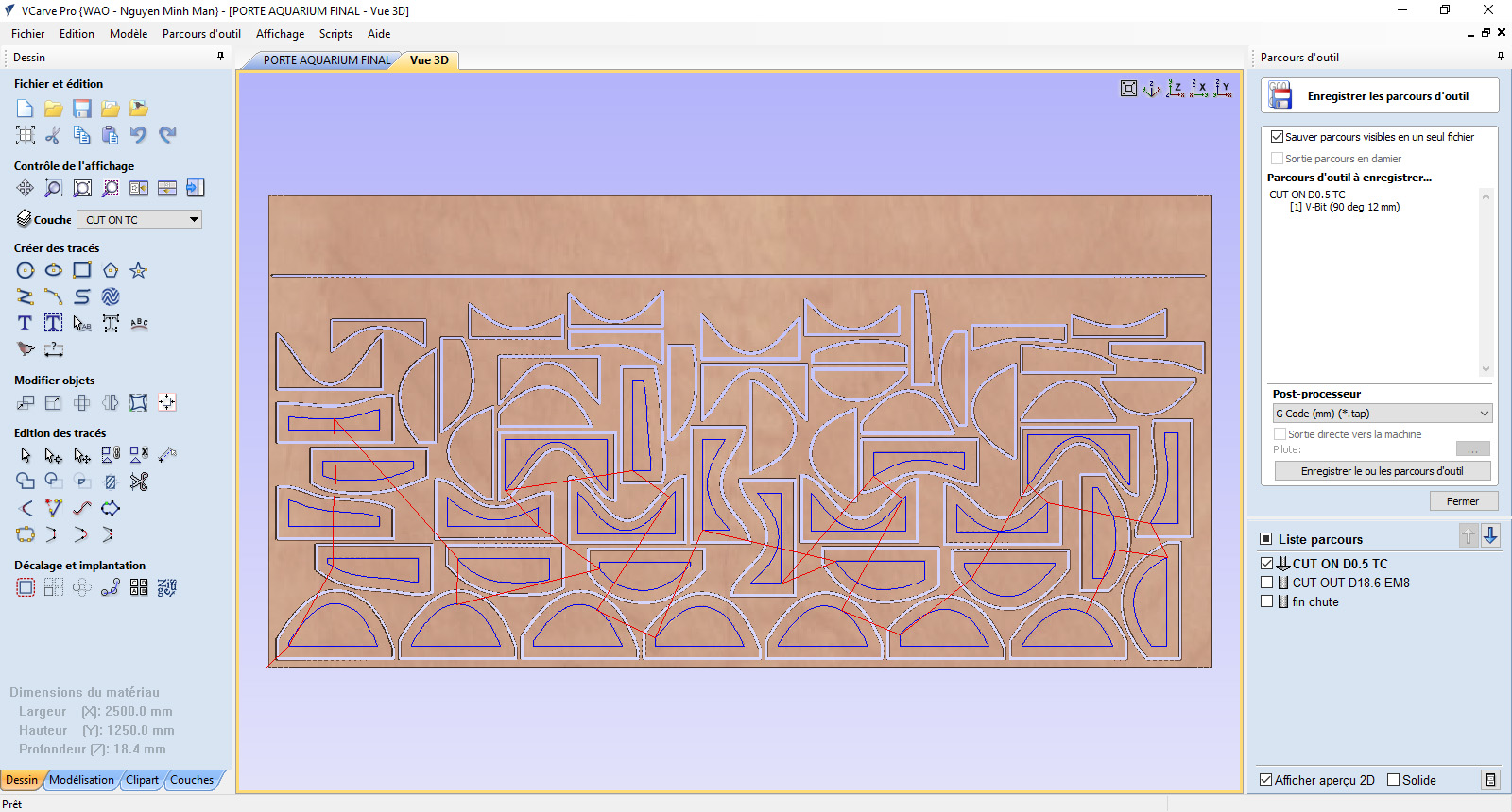
Finally you have to make a board like this and i have organized one layer for each milling job. My First layer in red nammed CUT OUT D18.7 EM8
and the second layer in blue nammed CUT ON TC. Now i can export in .DXF to open the file with V-carve pro.
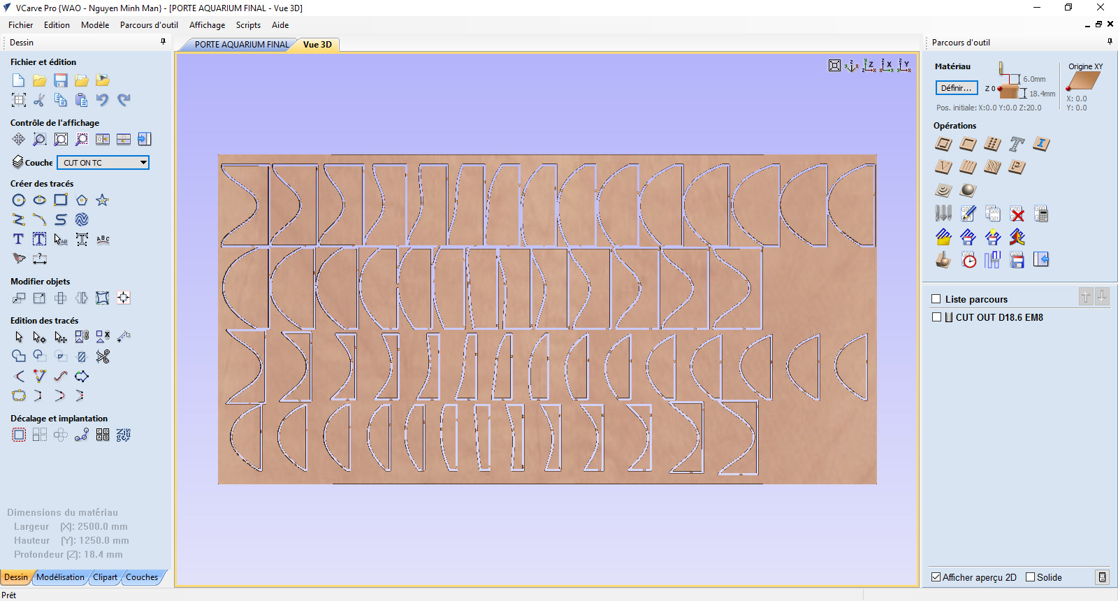
Step 7 : Open the job with V-Carve Pro
I set parameters of the materials, unit i mm, ans the scale.
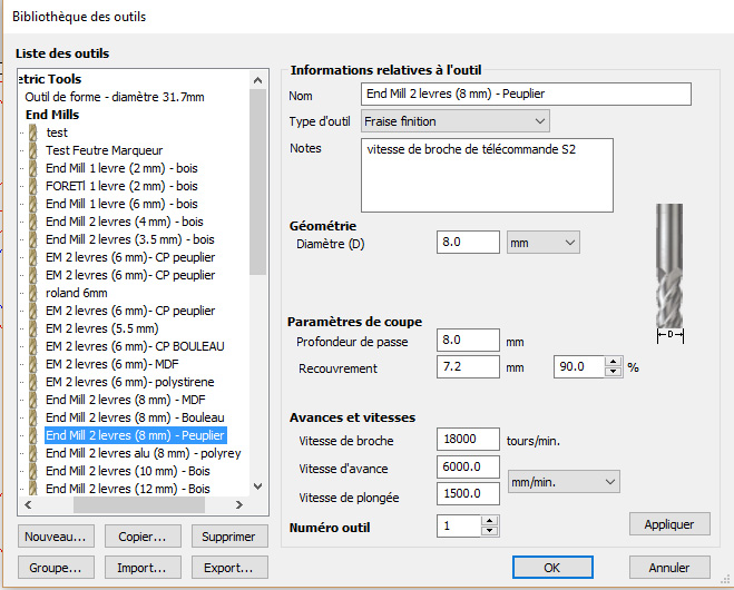
Then i set the parameters of the tools i want to mill. the type of tool, diameter, cutting parameter and the speeds.
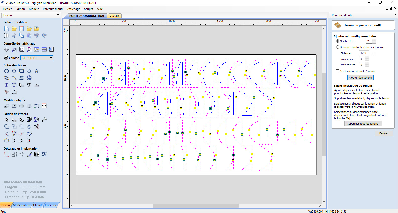
It is time to generate the tenon o the differents part of our object.
Layers by layers, of my dxf file, i set the differents jobs.
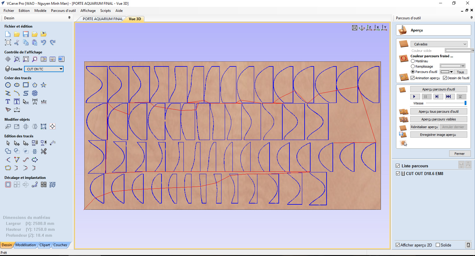
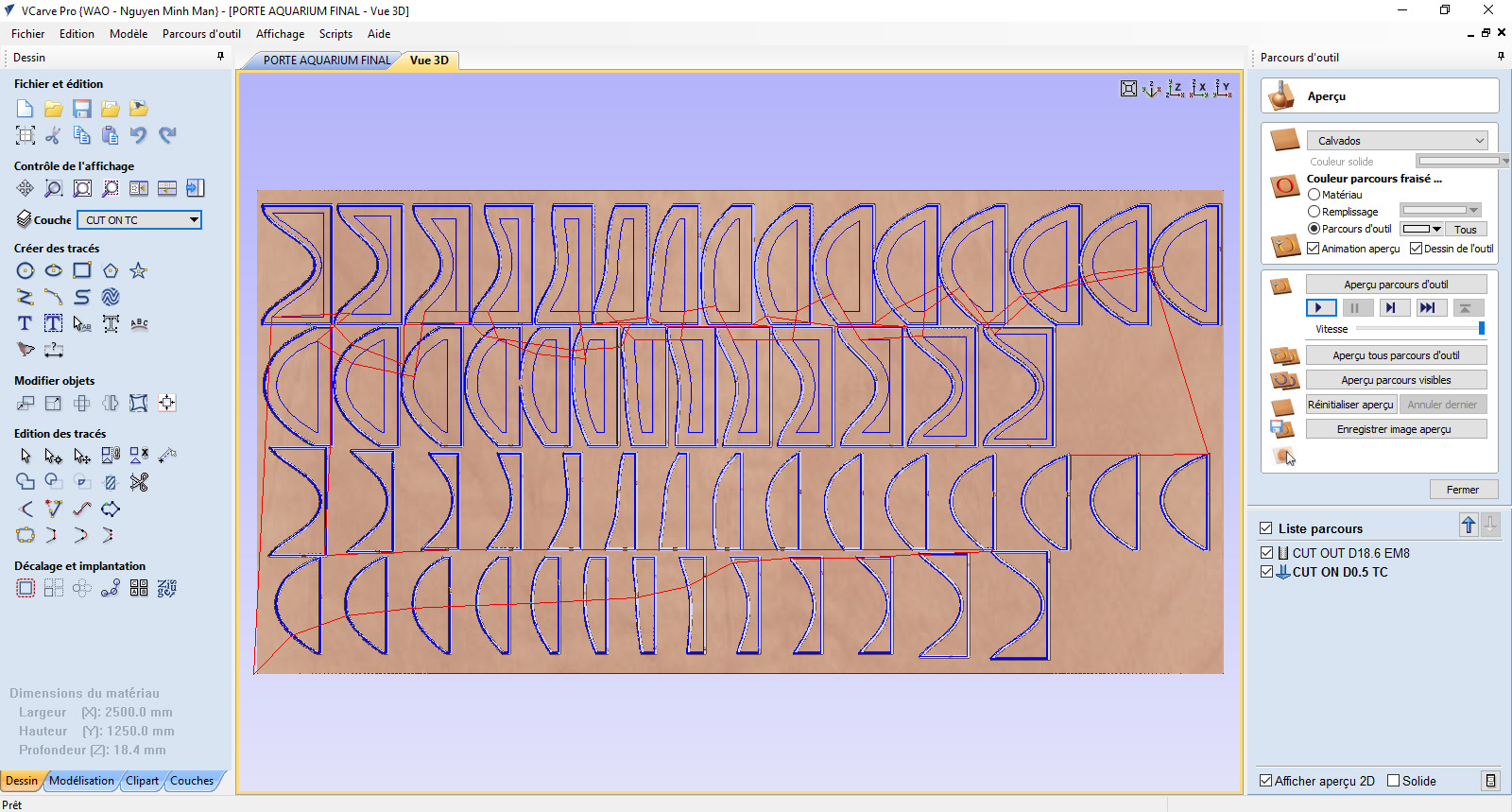
We can simulate the job when i click on "Apercu tous parcours d'outils"
I set the second job.
Now i set the order of the differents milling job.
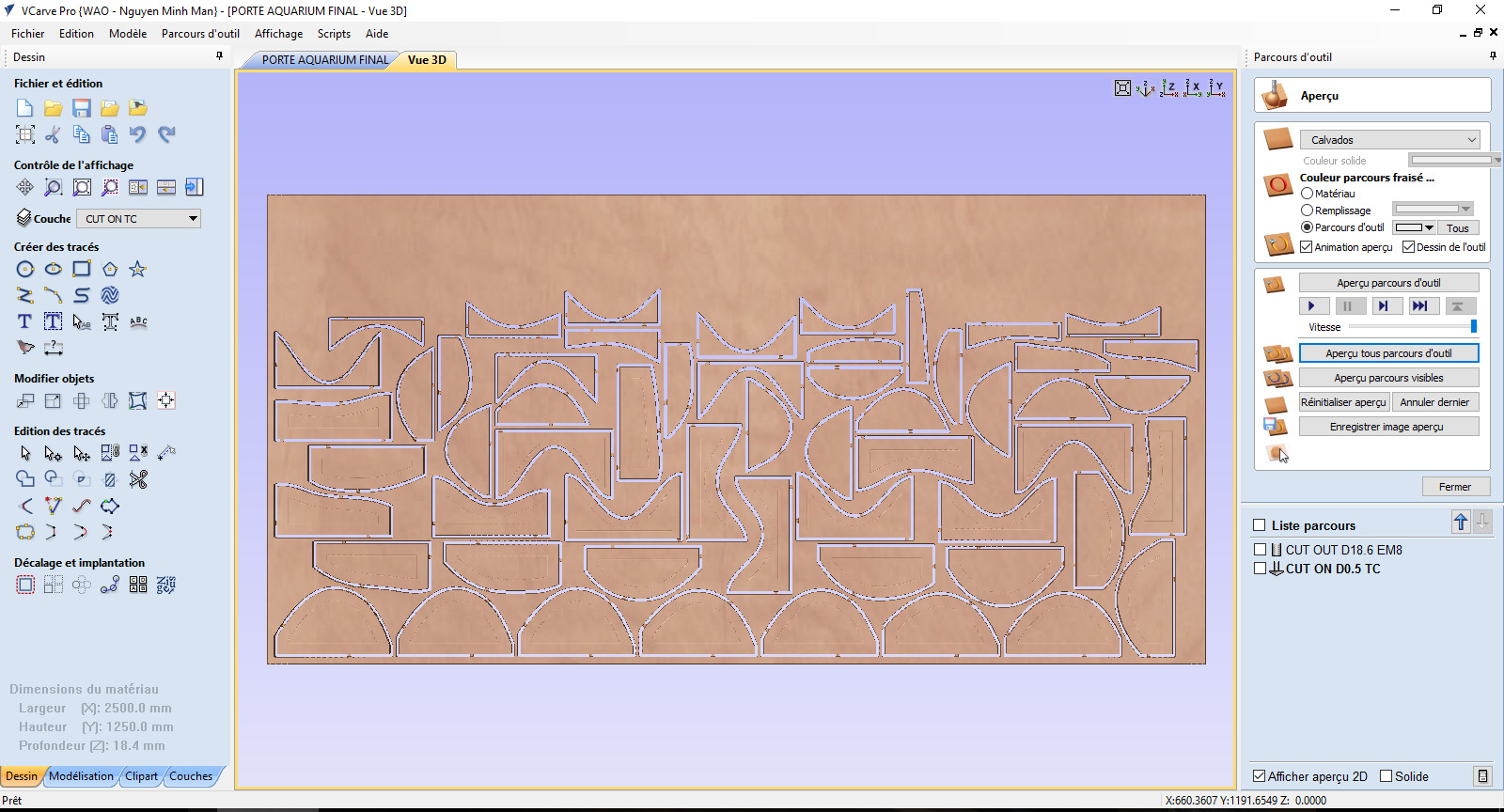
I optimised the board to mill without loss wood material. And save somme part to an other job.
Now i can export the job in g-code to mill my project !
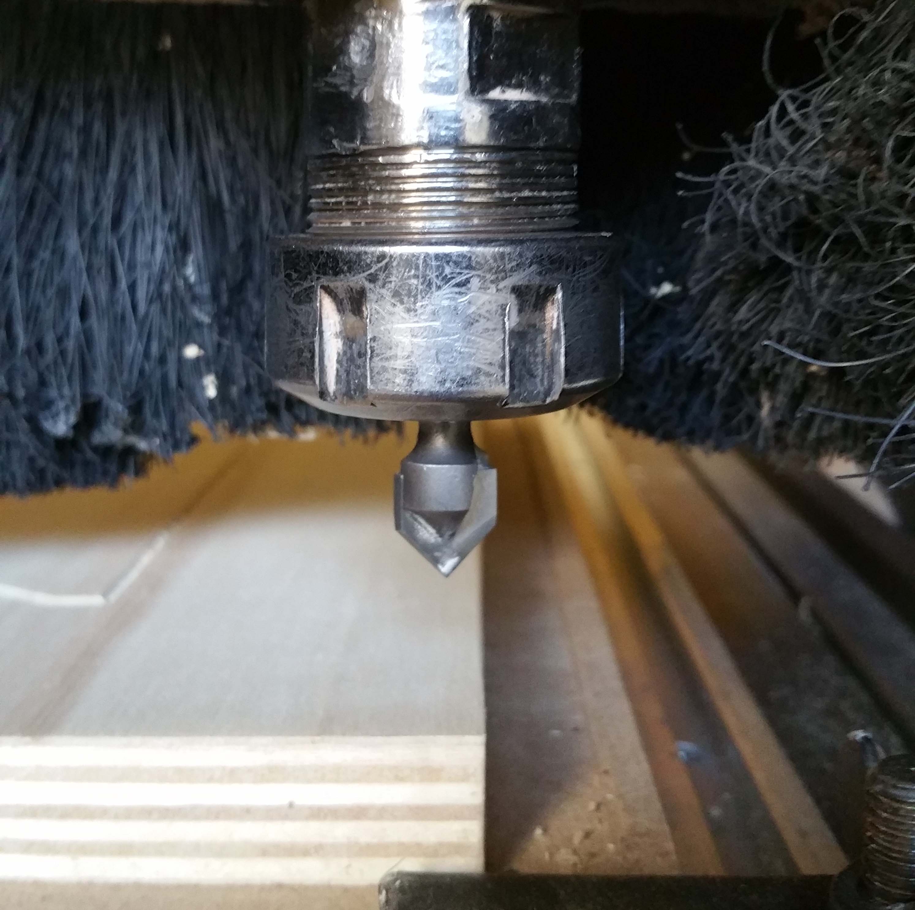
Step 10 : Start with the CNC milling machine
At first, i need to place my wood board and calibrate the cnc machine, in X Y Z.
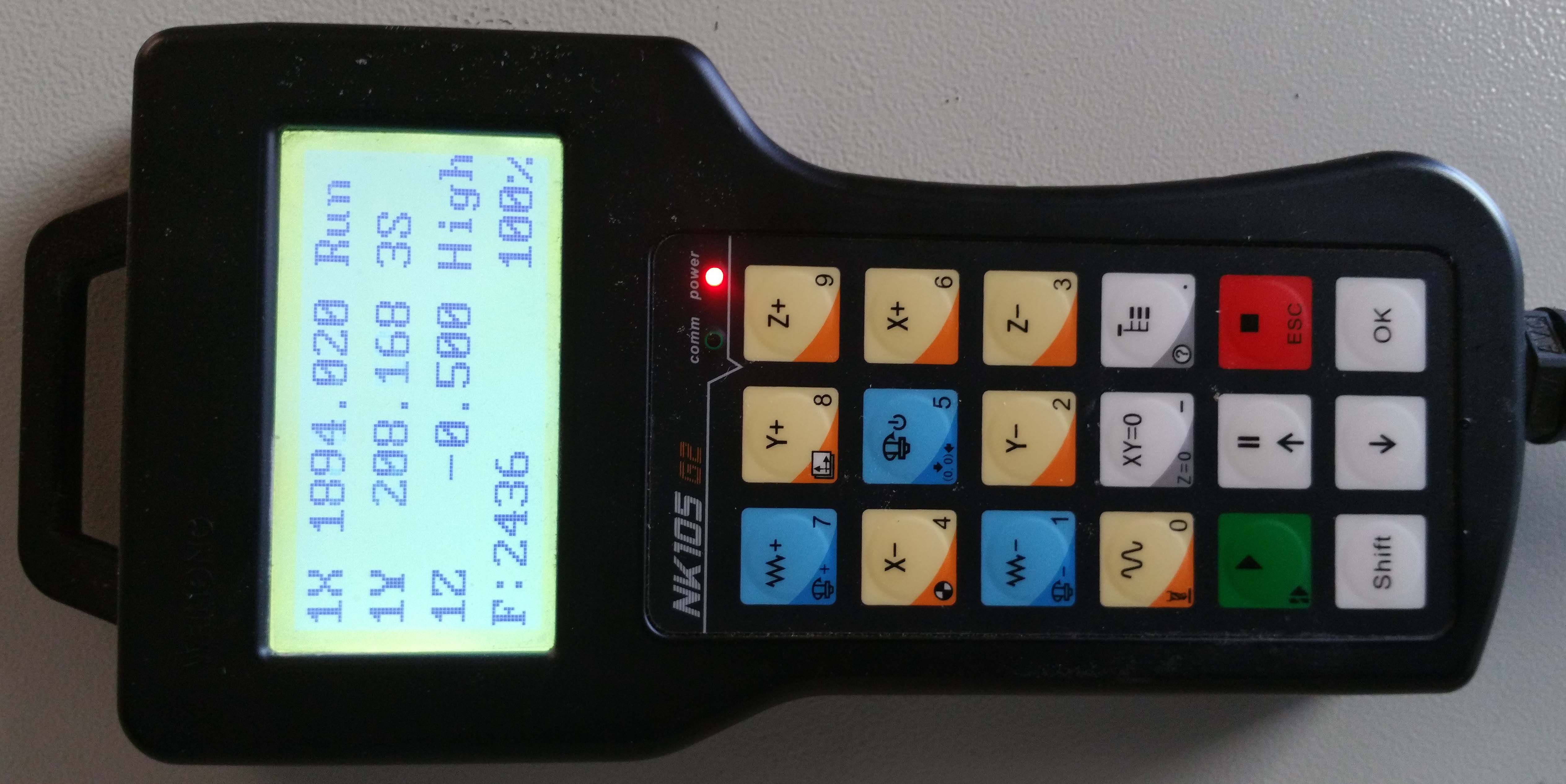
I use this controller to charge my file, calibrate and launch he job.
If i have a problem during the milling time i can stop the machine quickely with the stop button.
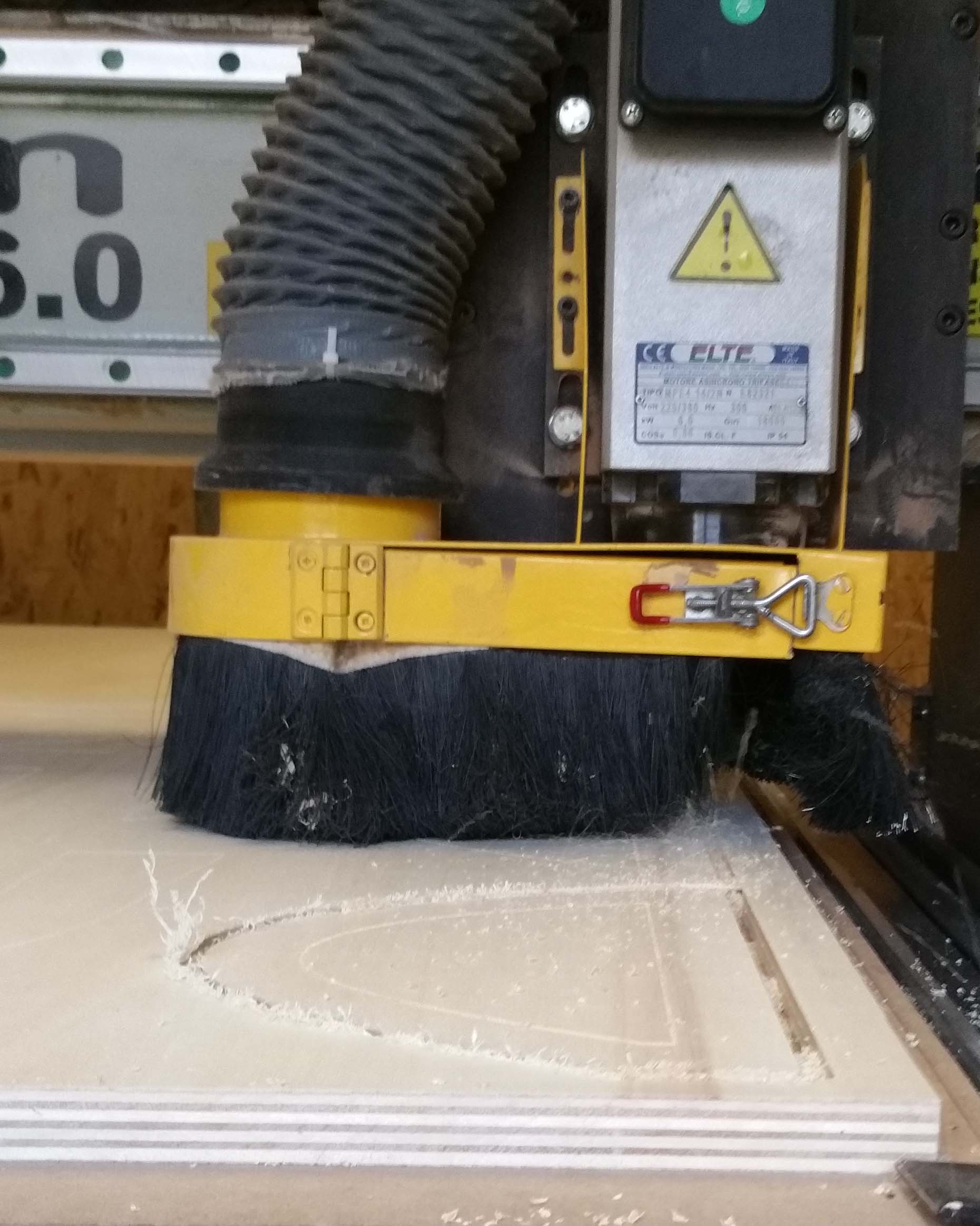
Let begin to mill !
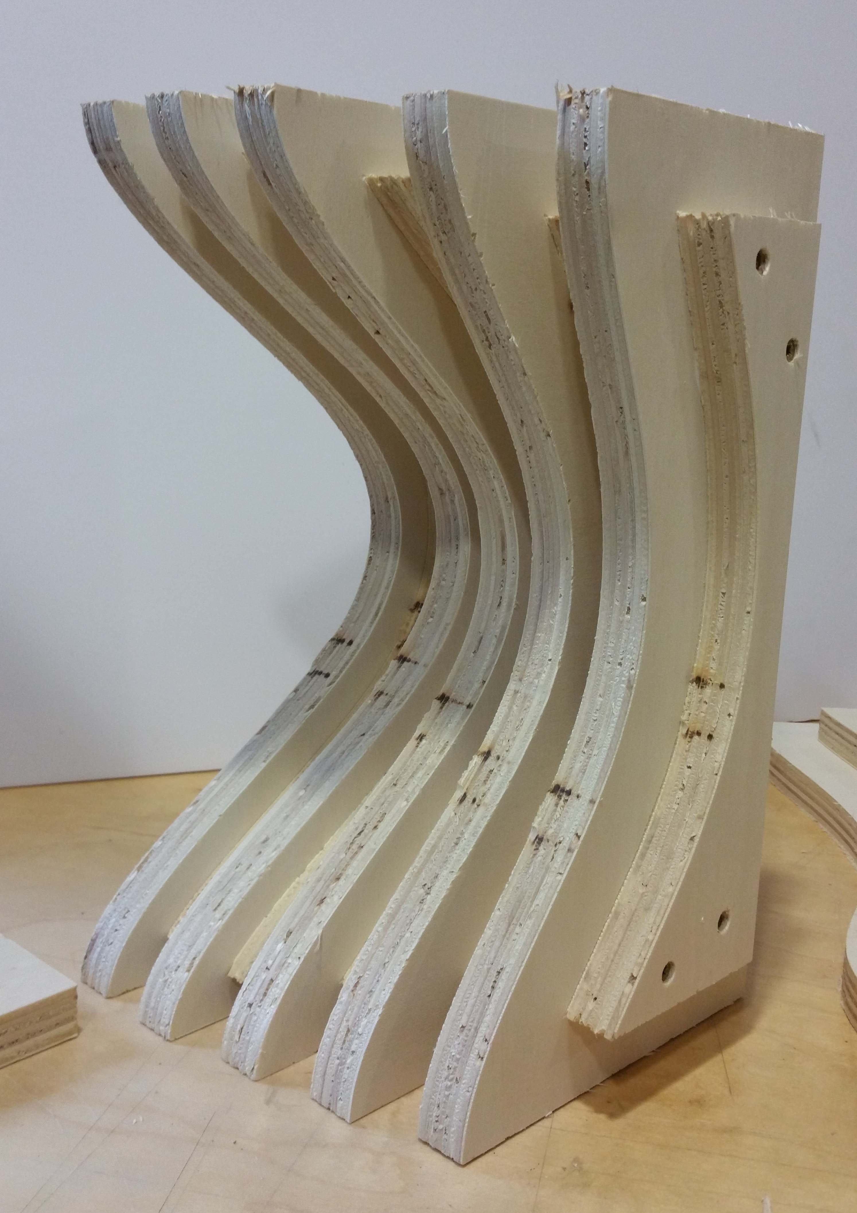
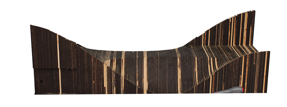
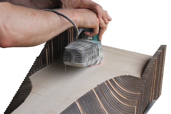
That's the result when the job finished. Now i have to sanding the all plate and extract the differents parts.
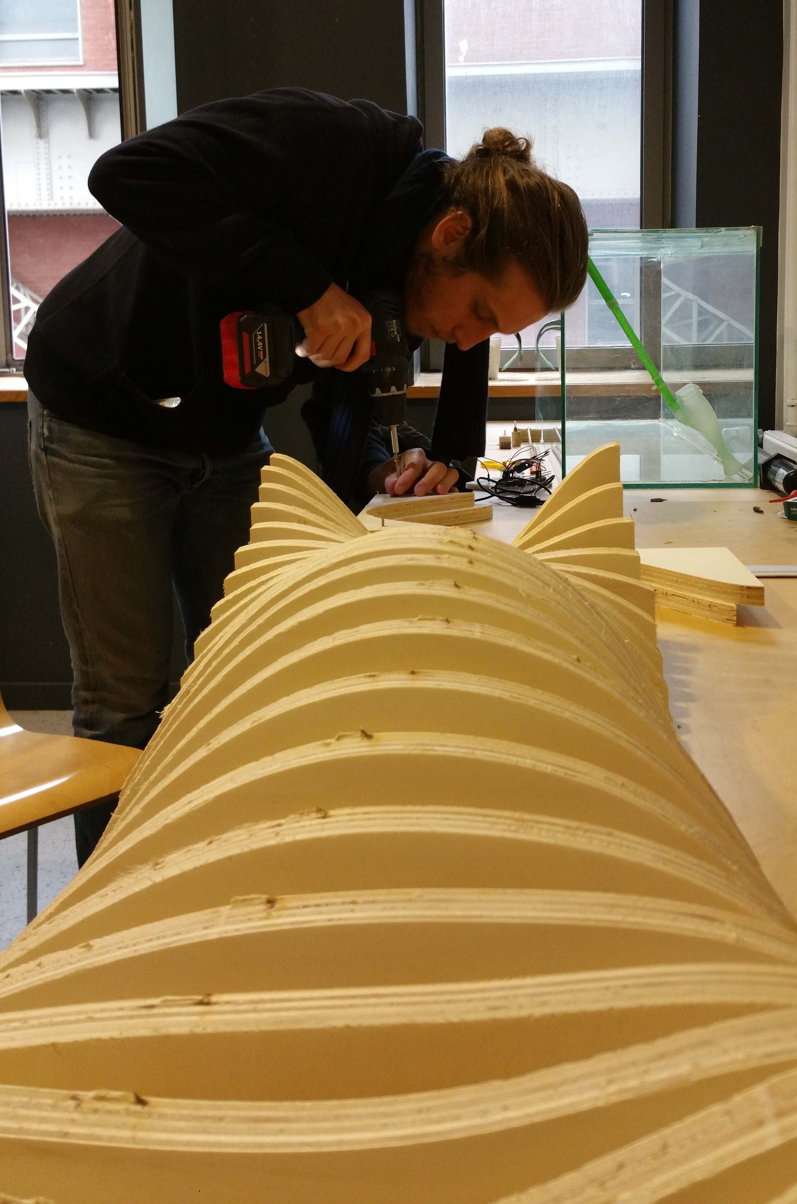
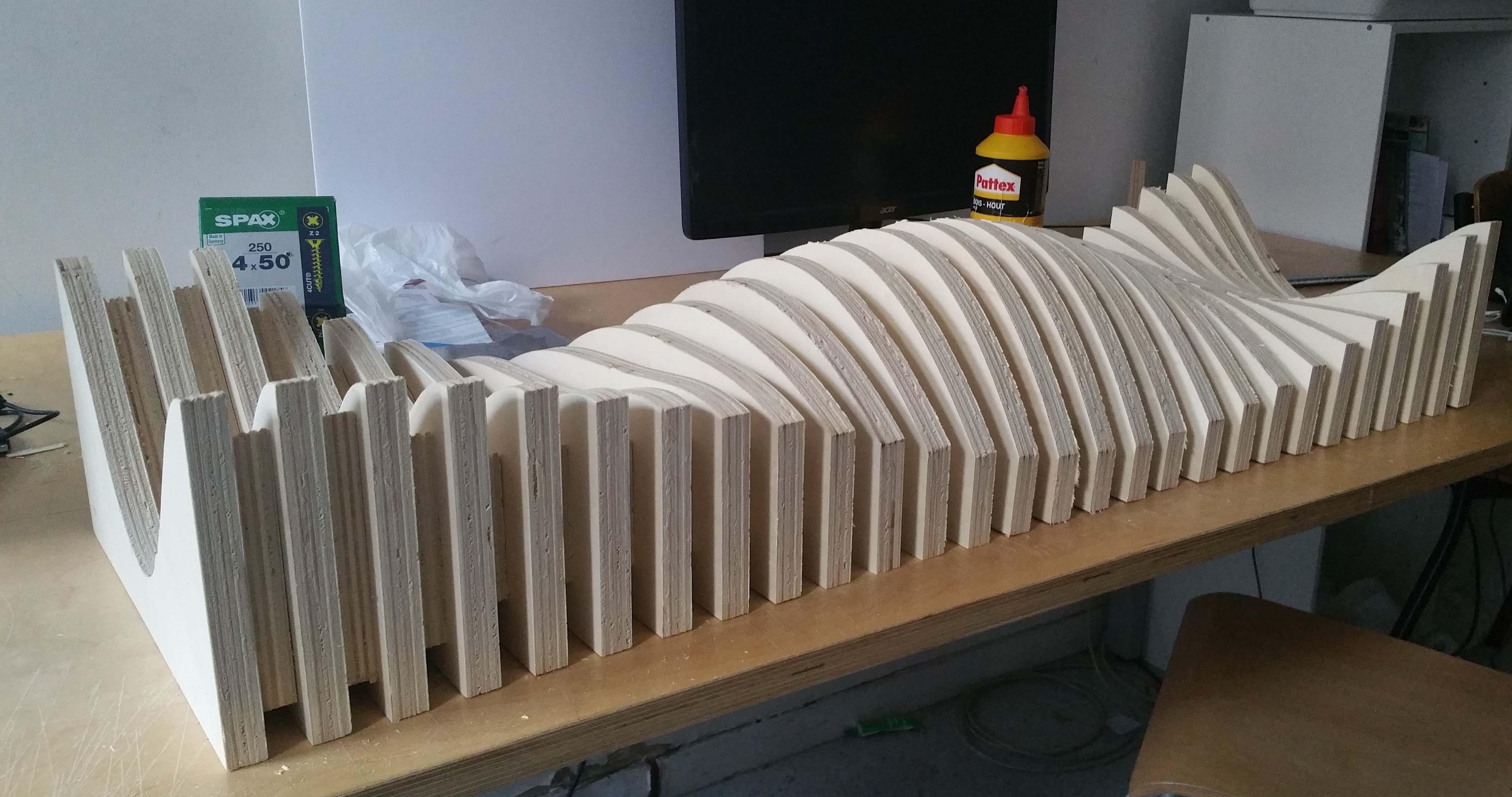
Step 11 : Assembly the project
I used screw to fix the differents part together.
Some help is welcome ! Thank you Florian for your good work.
All part are assembled ! I need to sanding right now.
Step 12 : Result
With this first prototype, i have a lot of change to make. I will make somes updates and probably mill the next version to the 3Weeks of my final project.
This week we will try to design something big with a cnc milling machine. We will start with rhino / grasshopper to design
something cool and learn how use a cnc machine. I decided to mill something for my final project. Then i opted for making an aquarium support. Let's go !
Step 1 : Generate a serie of cutting surface
I want to make a biomimetic design to hold my aquarium. To make this by a simple way, i need generate a serie of plane. I draw a curve in hino
and i set my curve inside grasshopper. With a box move, and a box serie i can generate a serie of 31 curve in Y direction with a step of 1 unit.
I extrude all mu curves in Z direction to generate cutter plans.
Step 2 : Give a volume to your surfaces
To have a volume to mill, need to extrude all my plans in y direction with a distance of18mm as the with of the wood plate we have.
Step 3 : Design a smooth nurbs surface
In order to give some curvature we will try to design a nurbs surface to ha a smooth result.
Step 4 : Cut your volumes with this nurbs surface
We will use our smooth surface to cut all the surface and give a beautiful sinusoïdal continuity to them.
You can name the wire using this icon :
We can see on this picture, the shape we have and how the plate be holded on this support.
Step 5 : Design the connection structure between the volumes generated
I modelise the plate holded on the structure.
I extract the connection between the different part of the object.
Now i extract the curve that i need to mill with the machine.
Step 6 : Prepare the file to export in DXF
Finally you have to make a board like this and i have organized one layer for each milling job. My First layer in red nammed CUT OUT D18.7 EM8
and the second layer in blue nammed CUT ON TC. Now i can export in .DXF to open the file with V-carve pro.
Step 7 : Open the job with V-Carve Pro
I set parameters of the materials, unit i mm, ans the scale.
Then i set the parameters of the tools i want to mill. the type of tool, diameter, cutting parameter and the speeds.
It is time to generate the tenon o the differents part of our object.
Layers by layers, of my dxf file, i set the differents jobs.
We can simulate the job when i click on "Apercu tous parcours d'outils"
I set the second job.
Now i set the order of the differents milling job.
I optimised the board to mill without loss wood material. And save somme part to an other job.
Now i can export the job in g-code to mill my project !
Step 10 : Start with the CNC milling machine
At first, i need to place my wood board and calibrate the cnc machine, in X Y Z.
I use this controller to charge my file, calibrate and launch he job.
If i have a problem during the milling time i can stop the machine quickely with the stop button.
Let begin to mill !
That's the result when the job finished. Now i have to sanding the all plate and extract the differents parts.
Step 11 : Assembly the project
I used screw to fix the differents part together.
Some help is welcome ! Thank you Florian for your good work.
All part are assembled ! I need to sanding right now.
Step 12 : Result
With this first prototype, i have a lot of change to make. I will make somes updates and probably mill the next version to the 3Weeks of my final project.
With Arduino, Fab ISP and Atmel Attiny microncontroller
This week i will try to programming my echo hello bard with my fabISP. At first will will experiment arduino IDE, and arduino as a programmer. In the second time, i will try to program my attiny 44 with my fab ISP.
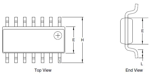
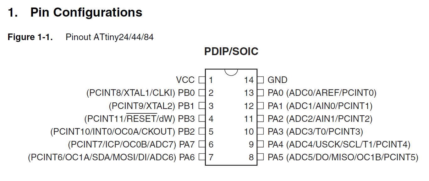
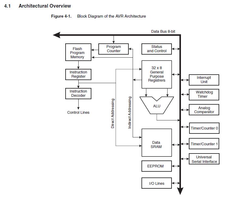
#1 : Read Attiny datasheet
I want to make a biomimetic design to hold my aquarium. To make this by a simple way, i need generate a serie of plane. I draw a curve in hino
and i set my curve inside grasshopper. With a box move, and a box serie i can generate a serie of 31 curve in Y direction with a step of 1 unit.
I extrude all mu curves in Z direction to generate cutter plans.
To have a volume to mill, need to extrude all my plans in y direction with a distance of18mm as the with of the wood plate we have.
#2 : Programming with arduino
Arduino is an open-source electronic prototyping platform enabling users to create interactive electronic objects. We will start to blik a simple led.
STEP 1 : Blink a led with arduino
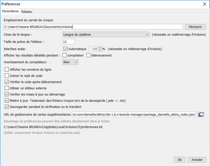
At first we can click Here to download arduino IDE and install it.
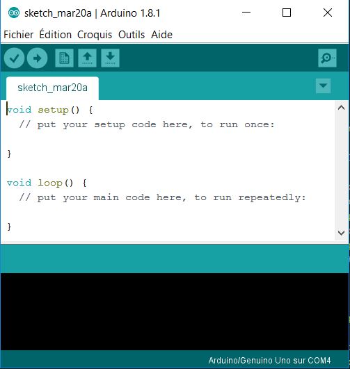
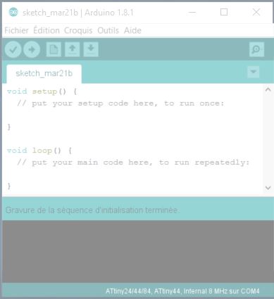
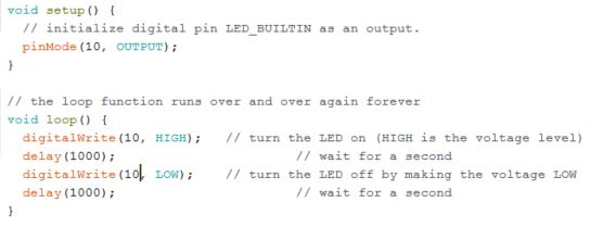
When you open arduino IDE, you get this interface as the next image. You can see that your program is empty. But you can already note the structure of your program with two functions : setup() and loop().
the function setup() will be launched when your arduino board start or when you reset your arduino. this function is executed just one time at the begining. Then the function loop() will will run unending, tha's why your programme can be executed and reply.
Open Arduino IDE
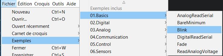
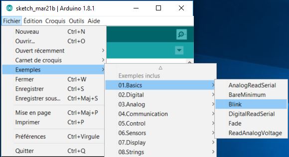
Load a basic sketch into arduino board
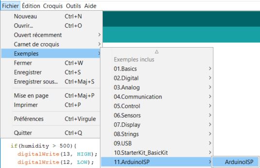
Now we will use a ready for use sketch in the arduino IDE. To open the sketch you have to click files > exemples > 01.Basics > Blink .
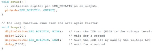
Now i have the sketch to blink the led 13 of my arduino board
We can verify the sketch when we click here :
And when you have connected your board to your comptuter you can click here to send the sketch :
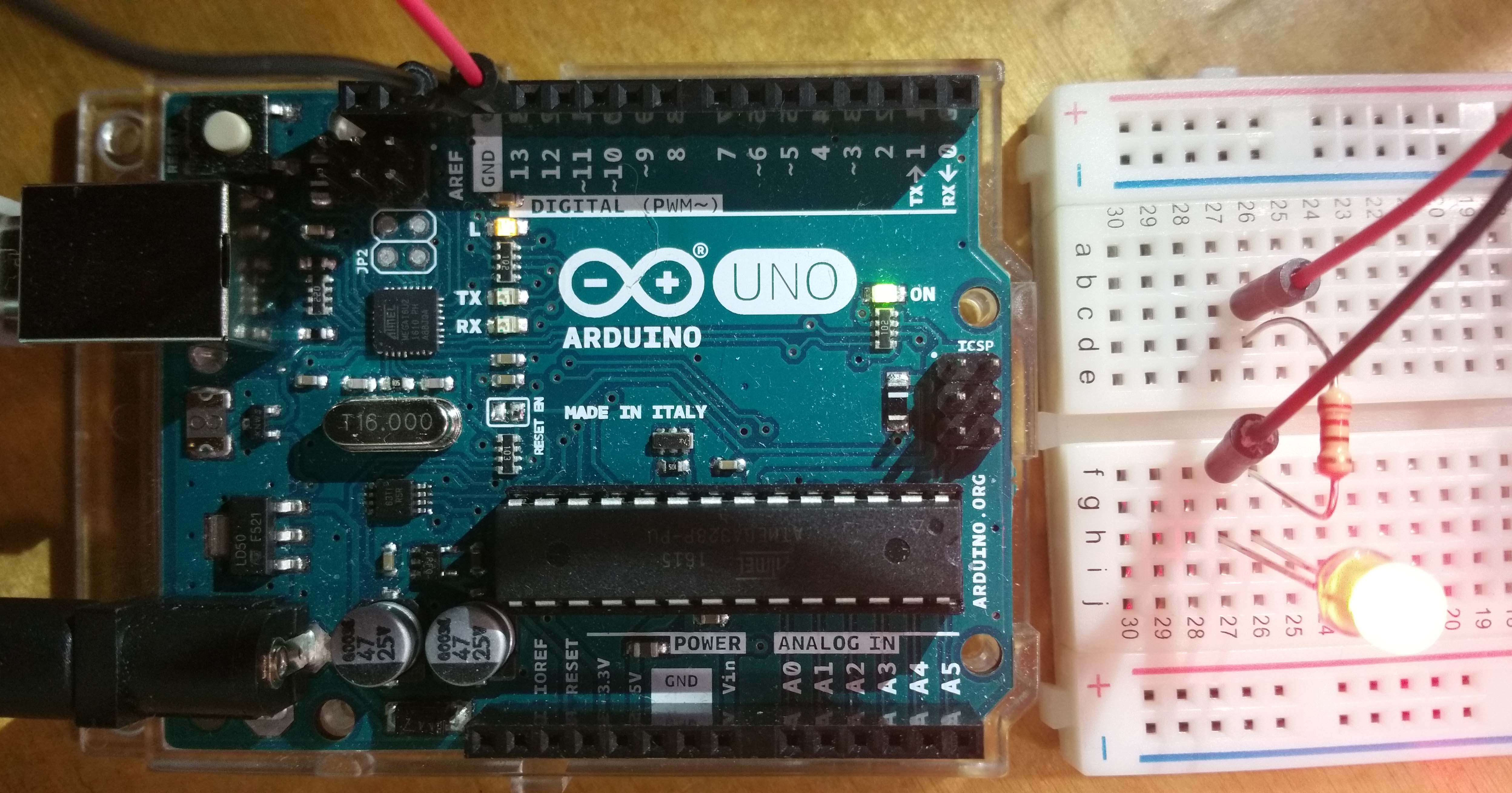
Now your arduino is blinking ! hello world !
STEP 2 : Multiple leds blinking !
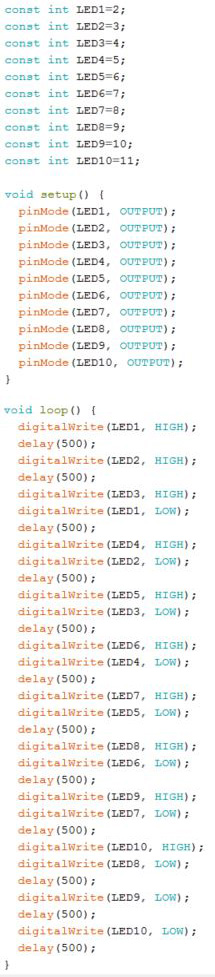
Now i will try to connect 10 leds and blink them. We will modify the program.
We create a constante for each LED with const int.
Then after the function void setup(), we use pinMode(pin,Mode) to set the output mode to every pin were a led is connected.
Then after the function loop(), we use he function digitalWrite(LEDX, HIGH); to light up the LED X, and digitalWrite(LEDX, LOW); to switch off the LED number X. To set the time of every command i use delay(T) with T in milisecond.
You can verify your script and launch it to the board.
Write the program
Blink a serie of leds
Now we can change the value of T in milisecond inside the expression delay(T) and launch the script to watch the difference of the light of the leds.
STEP 3 : Play with the buzzer
write the code
play electronic music
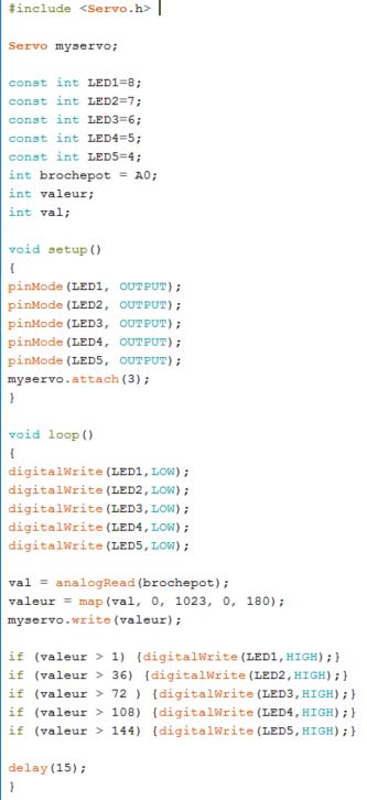
STEP 4 : Control a servo-motor with a potentiometer
write the code
we have to import servo libraries with #include servo.h
give a name to the servo-moter with : Servo myservo;
write wich pin is connected to the servo-motor with : myservo.attach(3);
we have switch off every led with : digitalWrite(LEDX, LOW)
we recover the value of the potentiometer with : val = analogRead(brochepot)
we adjust the value to have an angle of 180 degrees with : valeur = map(val, 0, 1023, 0, 180);
we send this value to the servo-motor with : my servo.write(valeur);
we light up the led in fuction of the value of the potentiometer with : if (valeur > ANGLE°) (digitalWrite(LEDX,HIGH);}
play with the potentiometer
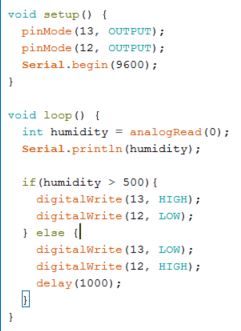
STEP 5 : a Watering warning light for plants
Now i will make something to help me to watering plants. To make this i need :
- 1 red led
- 1 green led
- 1 moisture sensor
- 1 arduino
- 1 breadboard
- 1 solar panel 1 Watt
- 1 battery 3.5 V 2500 mAh
- 1 LiPo Rider
write the code
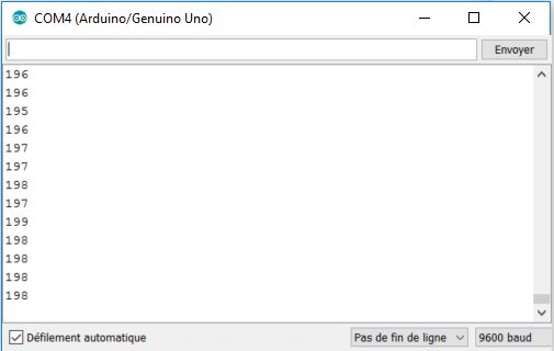
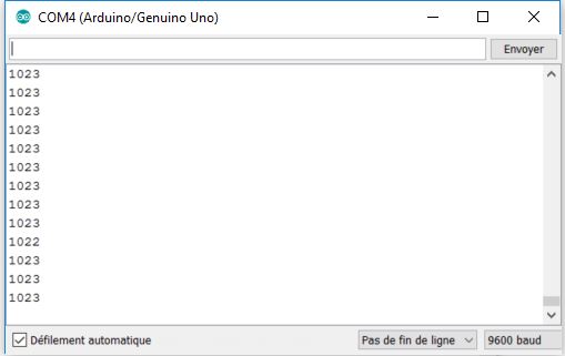
Upload the value of the sensor
This is the value when you have to give water to your plant.
This is the value when your plant have enough water.
Result
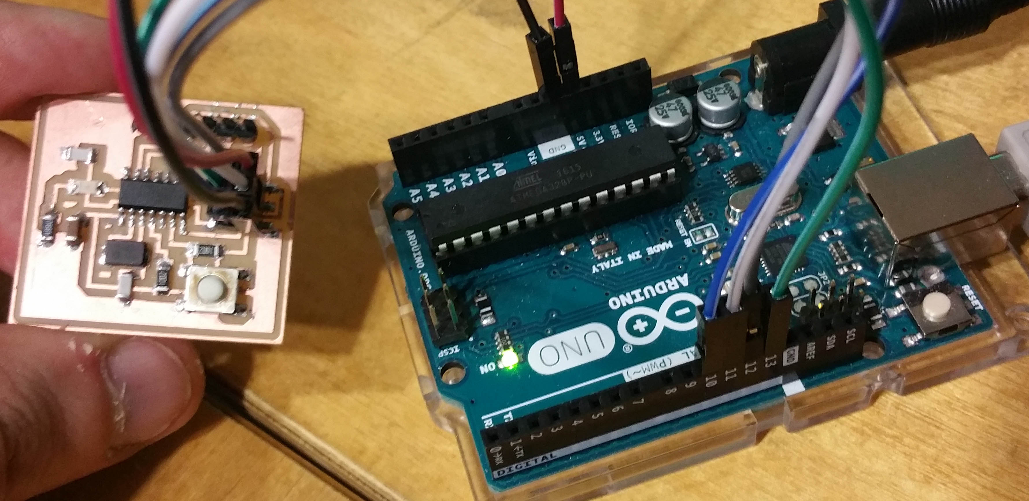
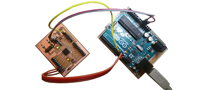
#3 programming the echo hello board with arduino as a programmer
STEP 1 : Use arduino as a programmer
Now i will try to use arduino as a programmer. At first we will open a sketch to upload to our arduino board.
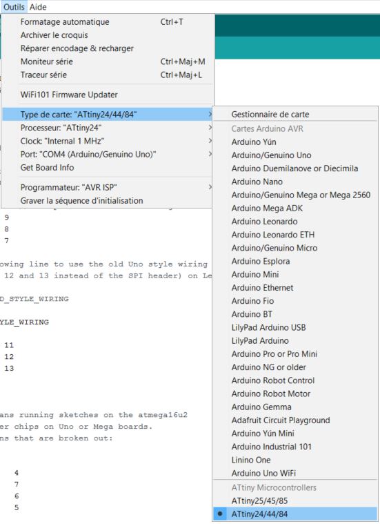
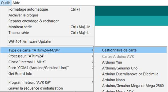
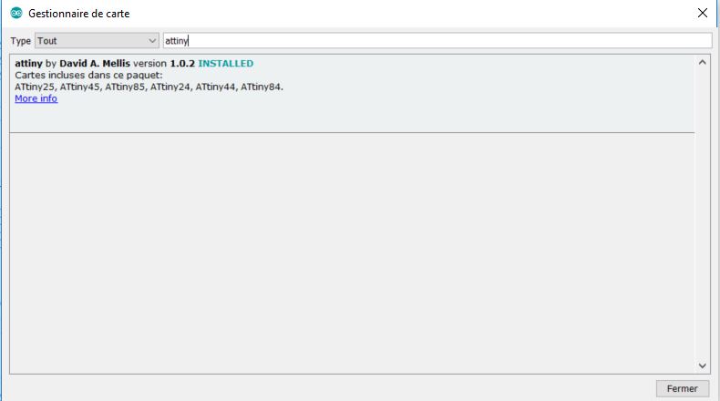
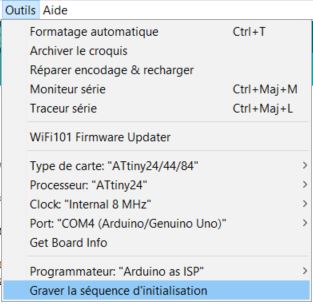
STEP 2 : Load libraries for attiny 44
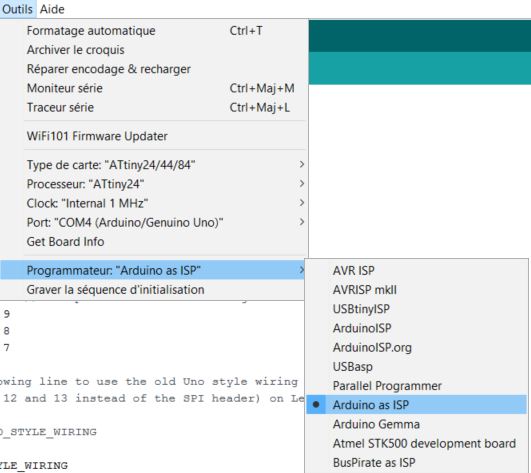
STEP 3 : Set arduino as ISP
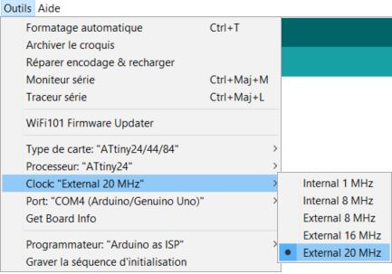
STEP 4 : Set the clock
STEP 5 : make the circuit
STEP 6 : Run the bootloader
STEP 7 : Blink the attiny 44 board
#3 programming the echo hello board with my Fab ISP
I have to finish this part when my board will blink.
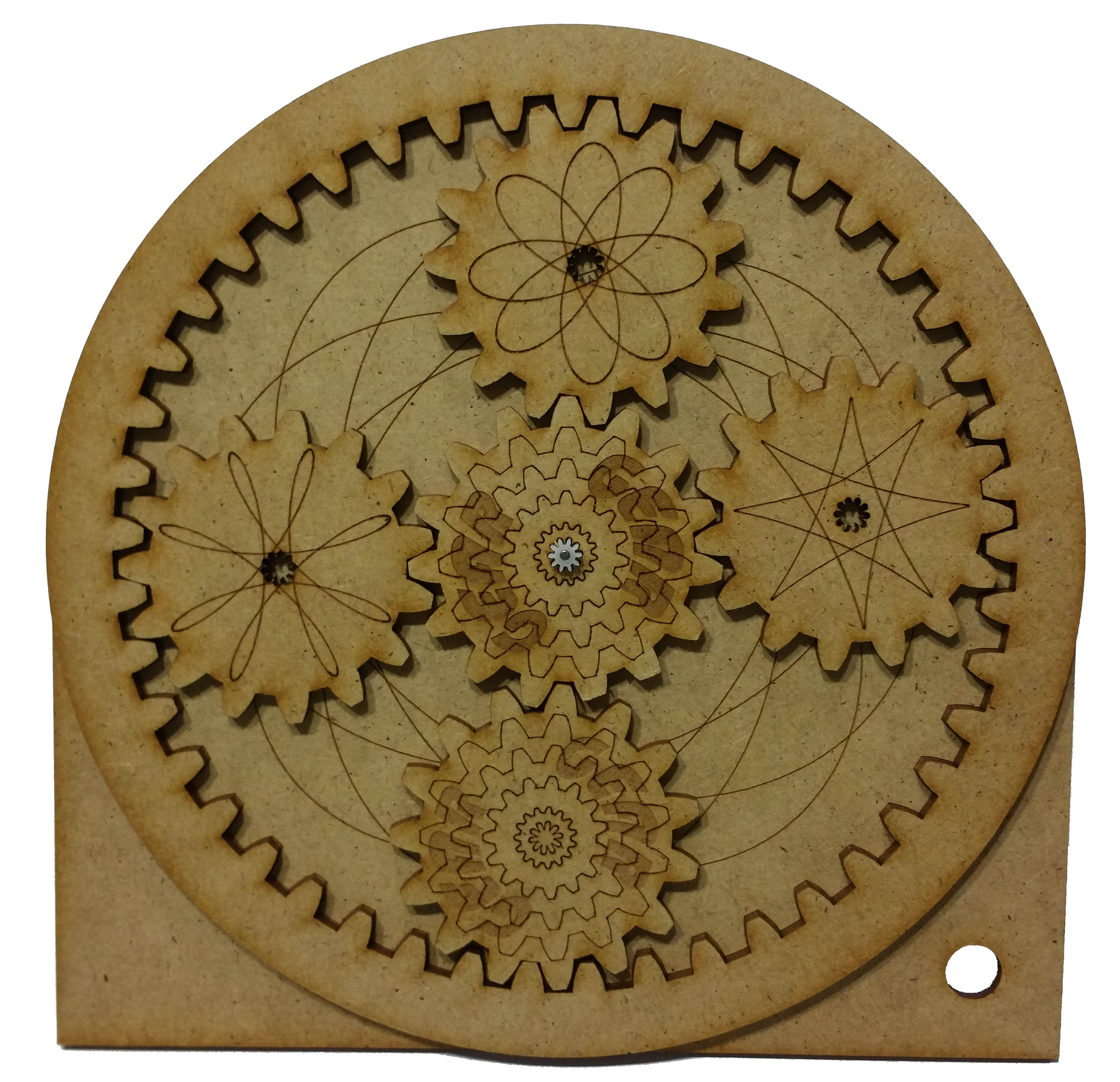
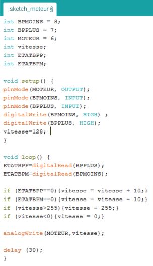
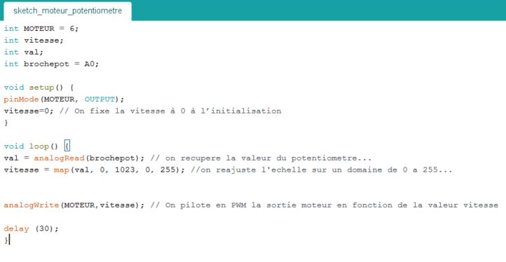
Programming a motor to controlling a gear
With Arduino at first, then a Atmel Attiny microncontroller
This week i will try to connect a cc motor with a microcontroller to control the speed of a gear with a simple potentiometer. Let's go !
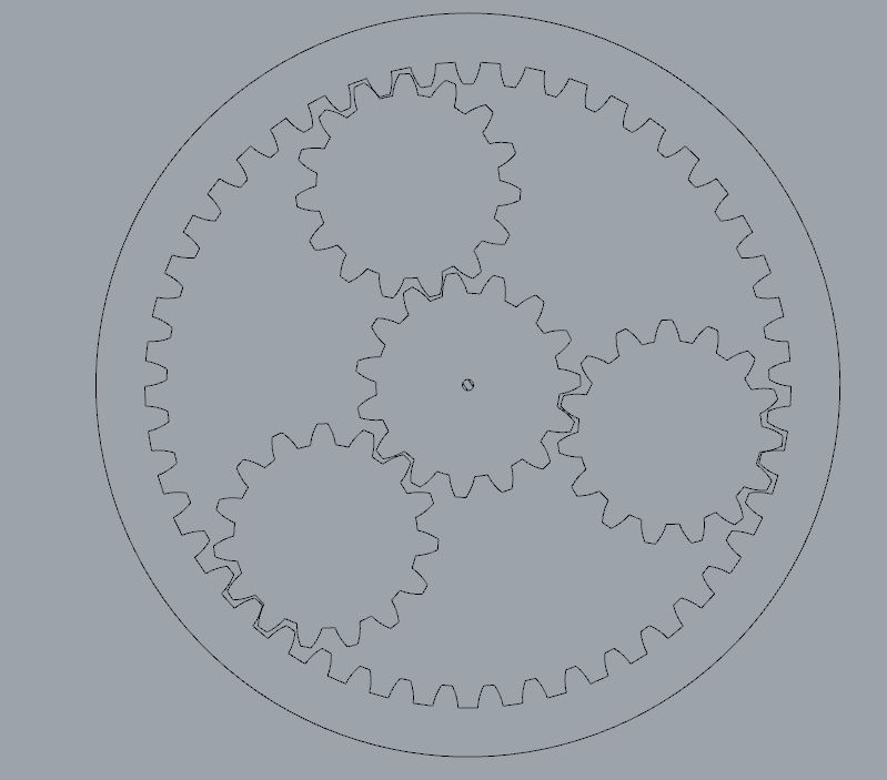
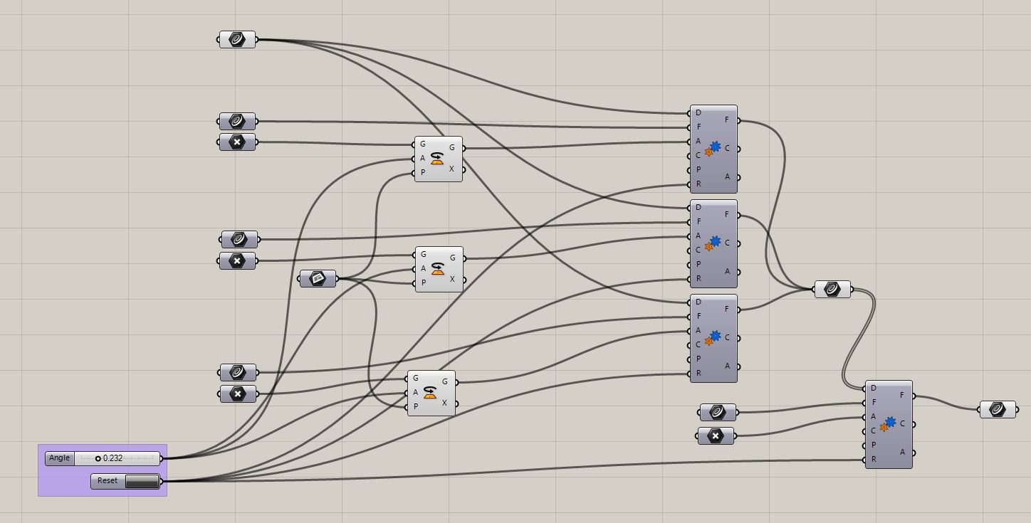
Step 1 : Simulate a gear with grasshopper and rhinoceros
The most simple solution to simulate a gear with grasshopper seem to use a grasshopper plug in name kangaroo. You can download it Here.
Kangaroo is a Live Physics engine for interactive simulation, optimisation and form finding directly with grasshopper. If you want to use this plug in you need download kangarroo 2.2.1 and kangaroo Physics 0.099. Because they working together.
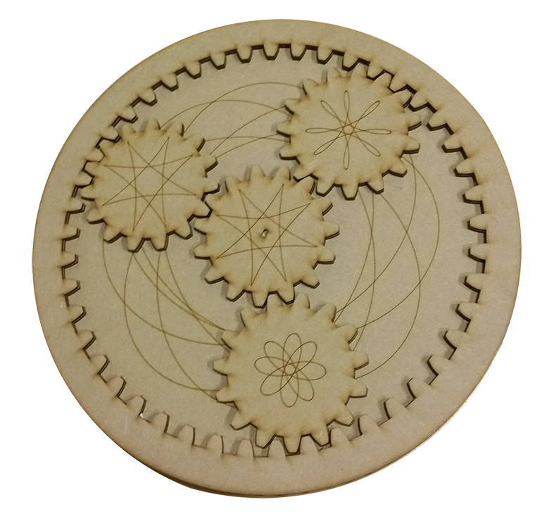
Now i draw a simple gear to begin with 4 pinions and one crank. I made the gear as simple as possible in order to make the simplest electronic prototype. It can evolve and become more complex in the machine design process.
Then when i have the gera i want as a simple closed curve i can load my curve inside the grasshoppper script to simulate the mouvement.
In this video we can see what happen in rhino when i change the value of the variable in my visual script in grasshopper.
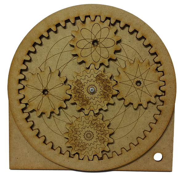
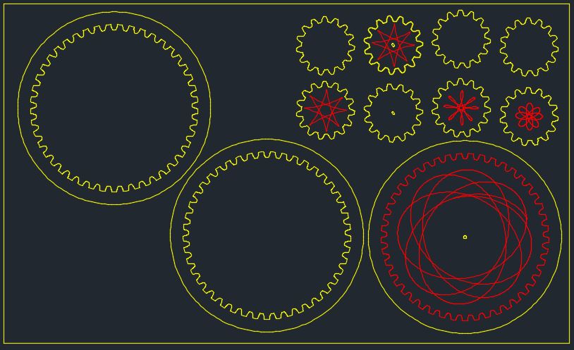
Step 2 : Lasercutting the gear
# First prototype
I started with a MDF 3mm board to prototype the gear. I prepair the file with AutoCAD. As we can see inside the next picture, every colour have a fonction: - Yellow to cut the bord - red to trace on the board.
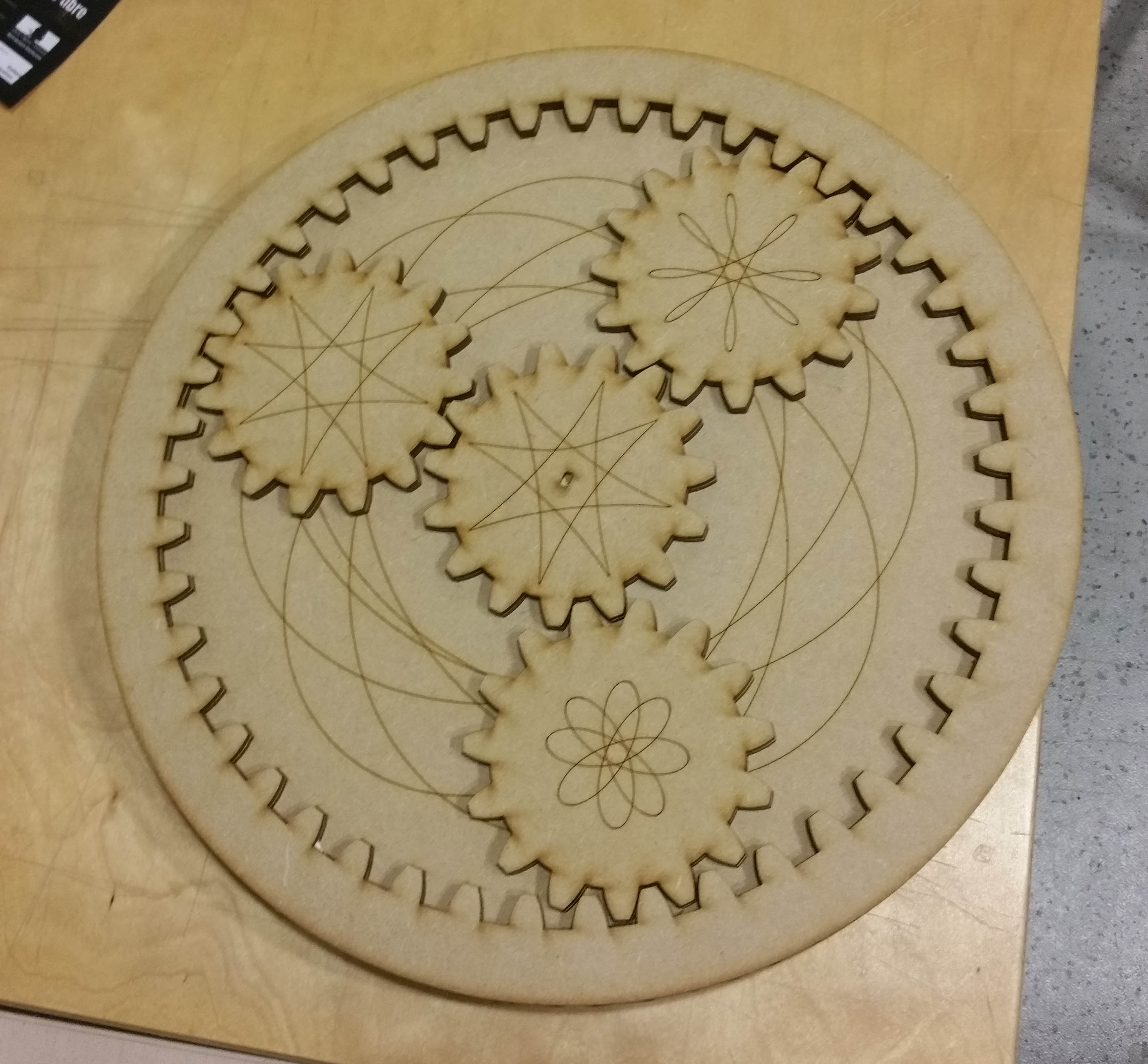
That's the result after cut and asembly the first gear prototype.
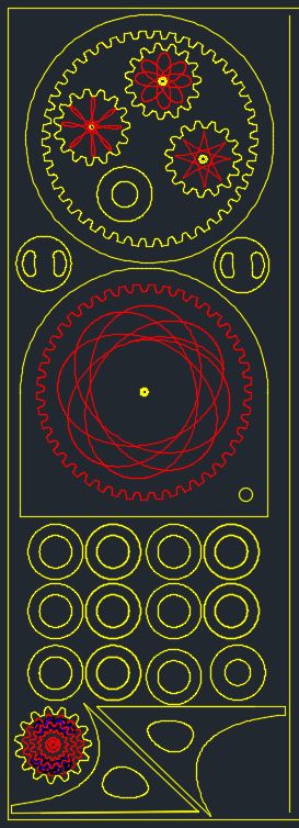
# Second prototype
The second prototype is smaller, lighter, consumes less material, can be placed on a table with its supports and work with a very small engine.
I created a little hole in the right. It let me to connect a potentiometer to control the speed of the gear.
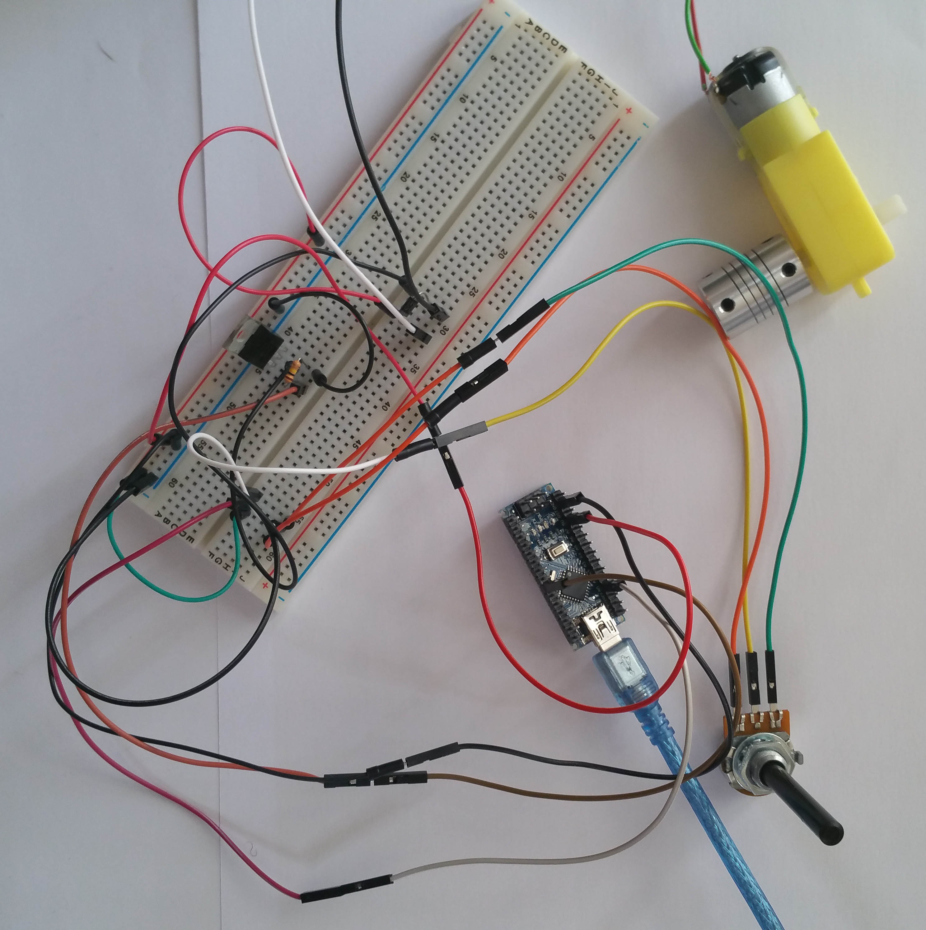
Step 3 : prototype the circuit with arduino
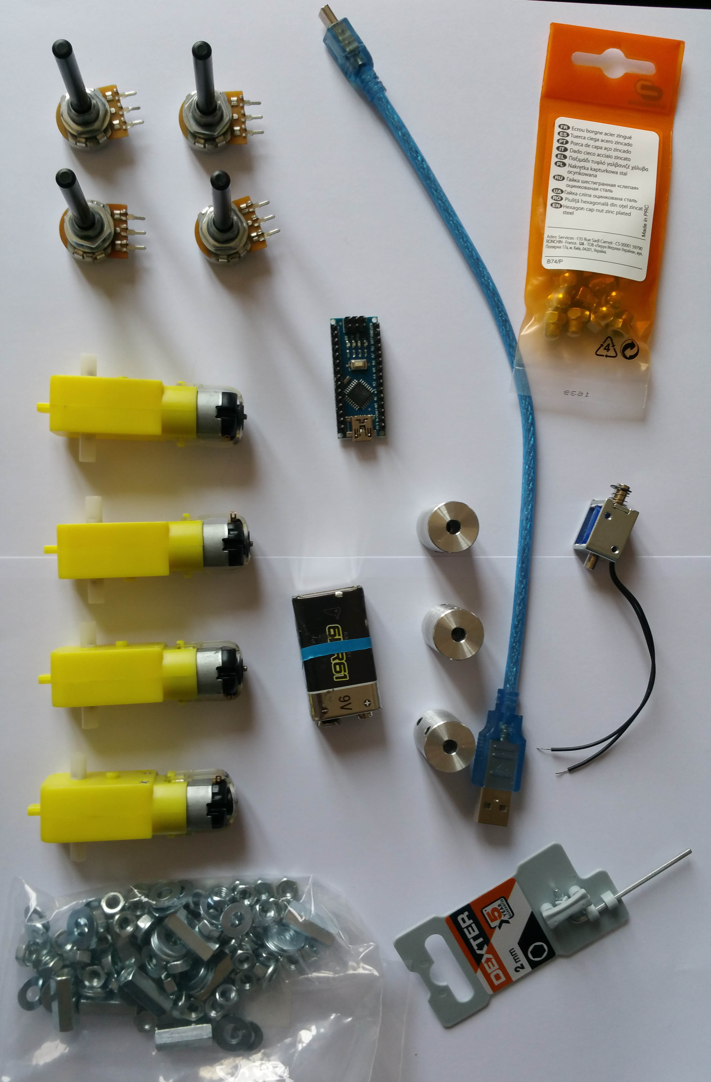
I used a very small cc motor with 2 buttons to crease or increase the speed. I don't know if the torque is enough to move the gear. But we wil try with this one. Maybe i will need a motor more powerfull.
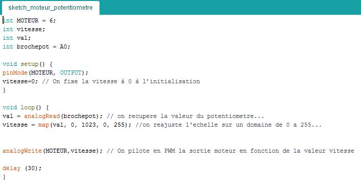
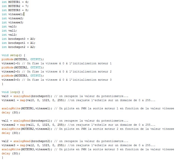
Now i will try to add a simple potentiometer to control the speed of the motor and modify the code to execute that..
This is the test of the prototype with the cc motor and a potentiometer control and tarduino board.
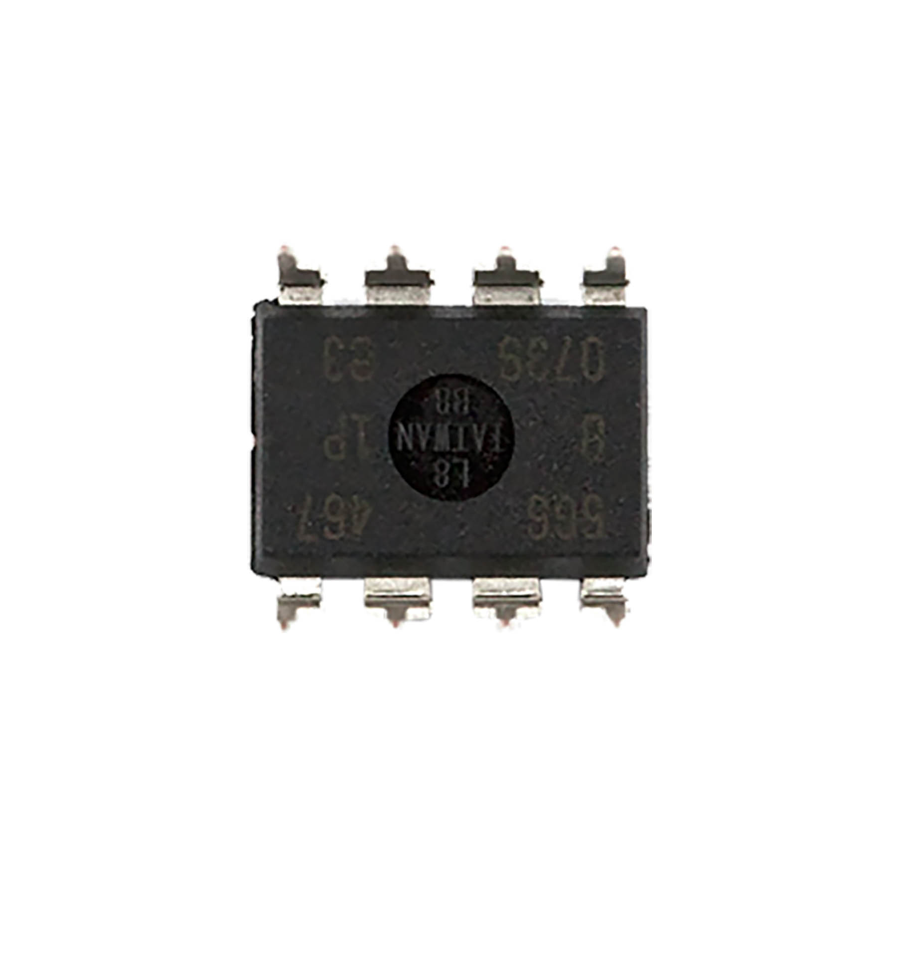
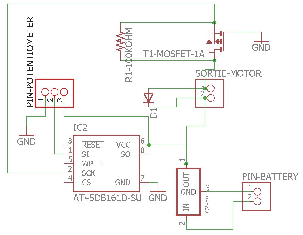
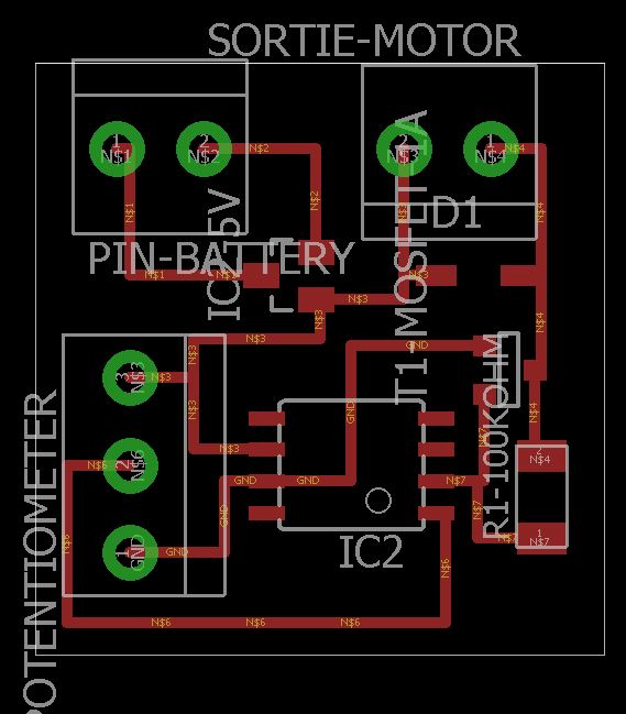
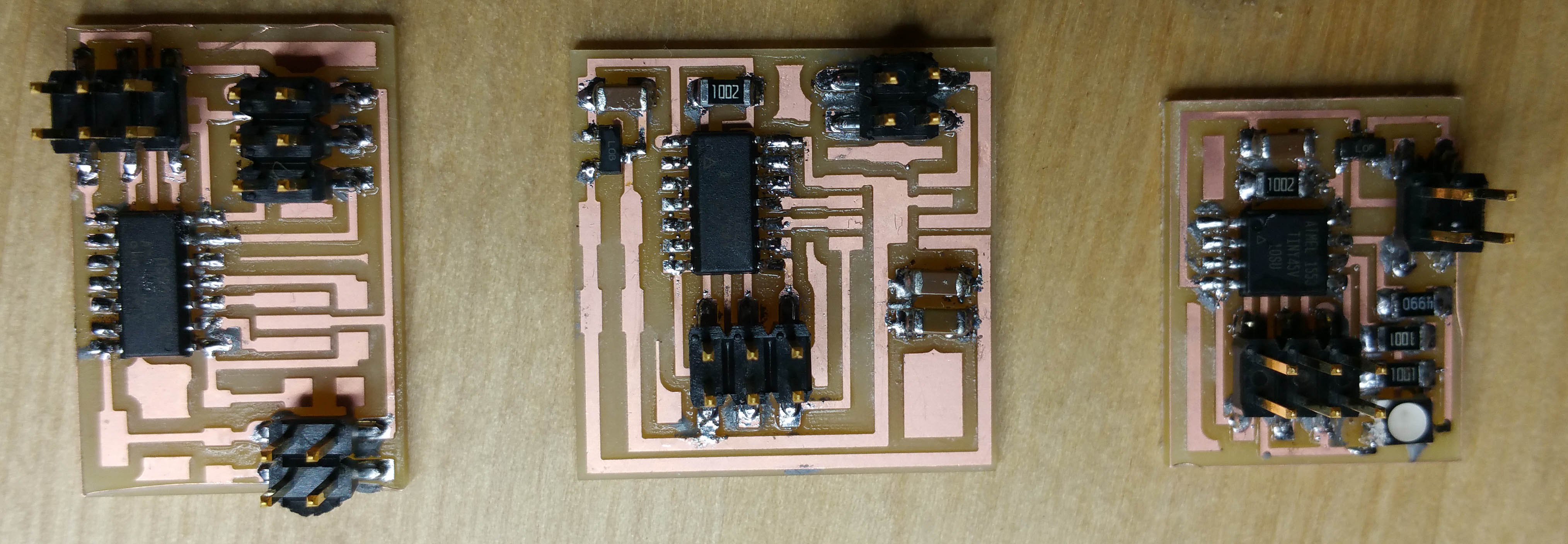
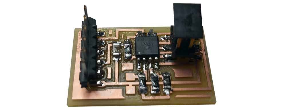
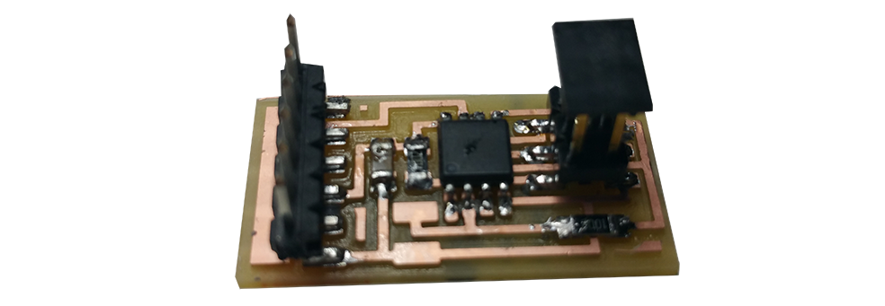
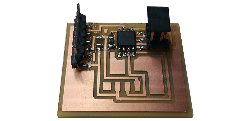
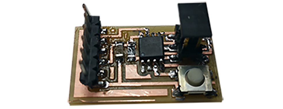
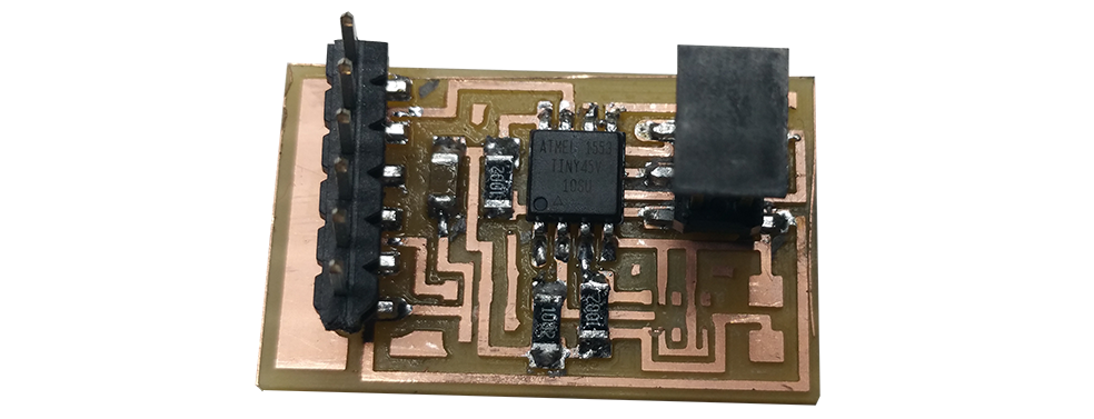
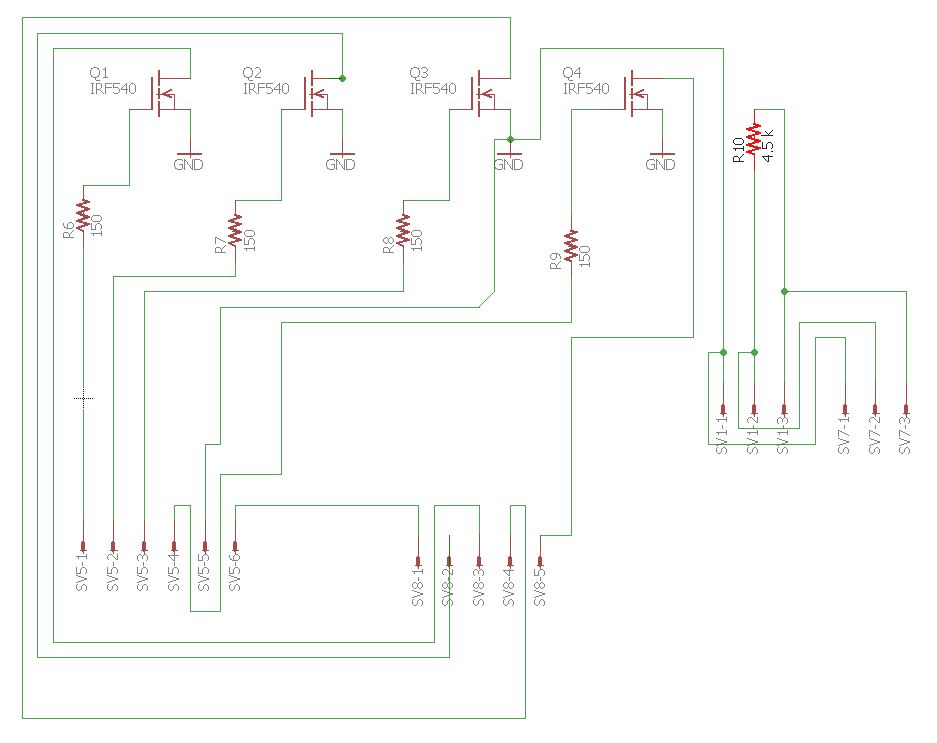
Step 4 : Make my Own board to control the motor
This circuit is very simple. I need : -1 Attiny 45 SI SOIC 8 - 1 Mosfet transistor SOT 23 - 1 diode SOD 123 - 1 resistor 100 kOhm boitier 1206 - 1 cc motor - 1 potentiometer - 1 pin header 2x3 smd
I will draw the board with eagle and mill the board to finish this prototype.
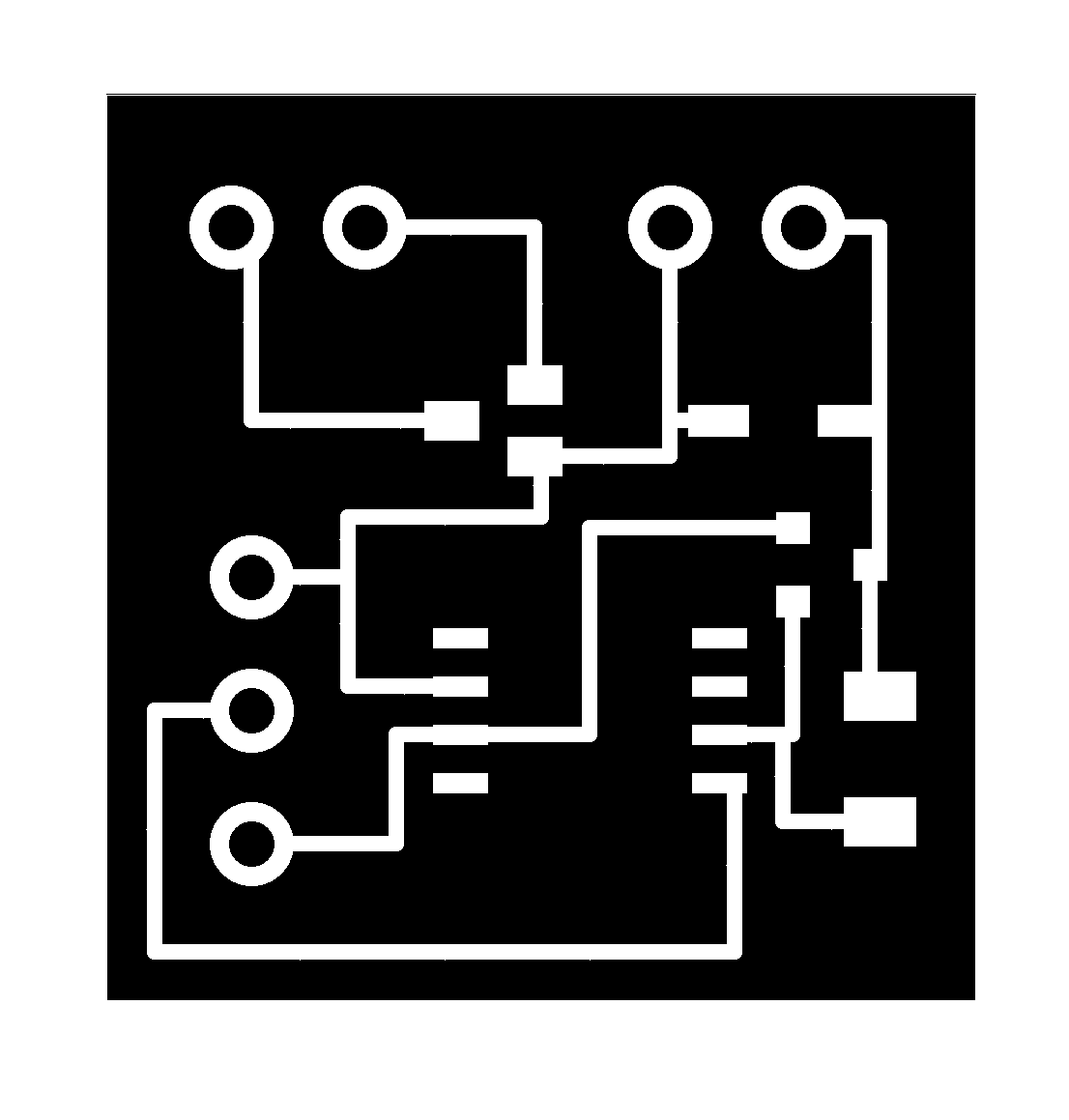
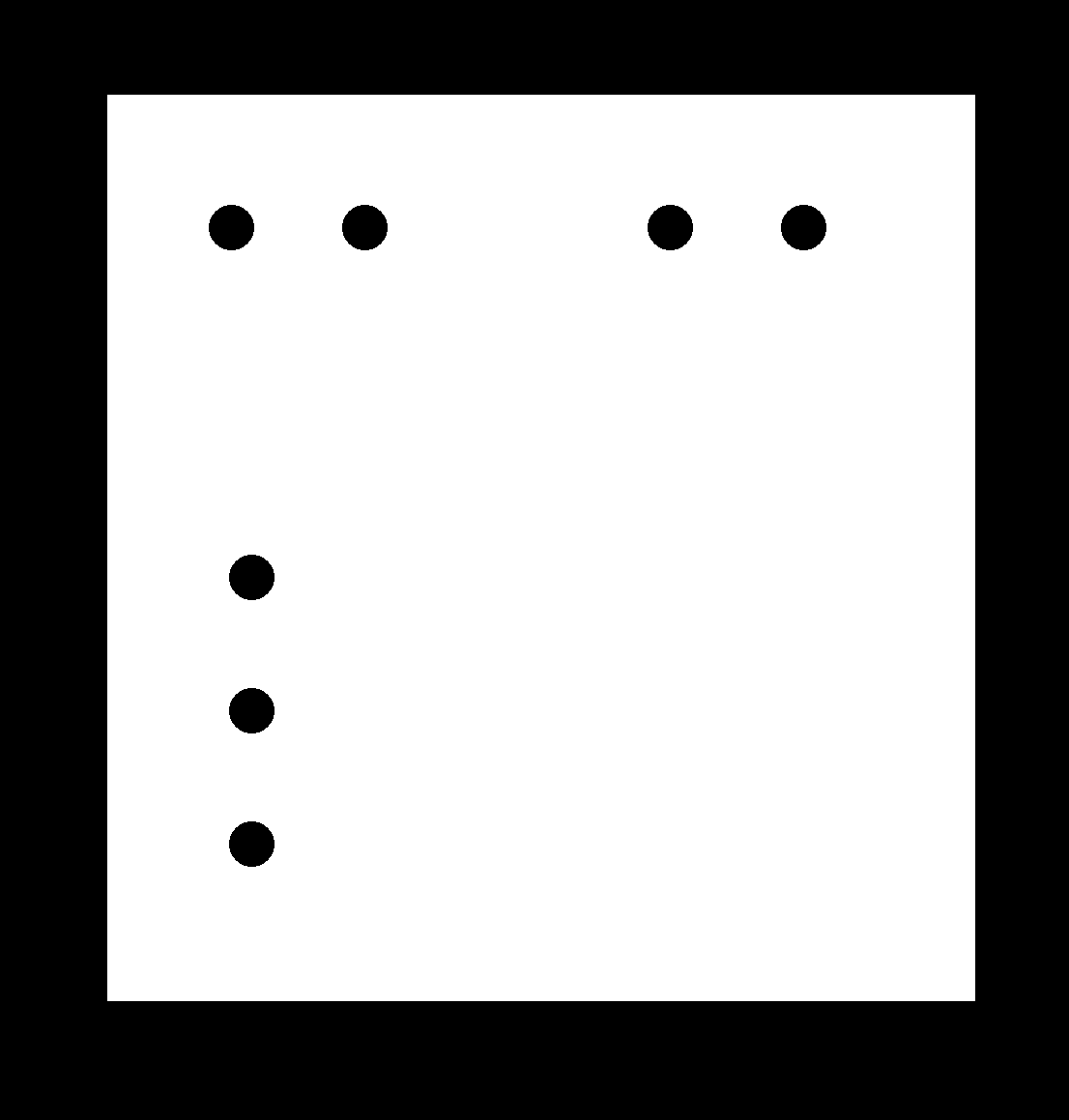
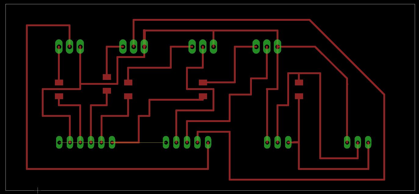
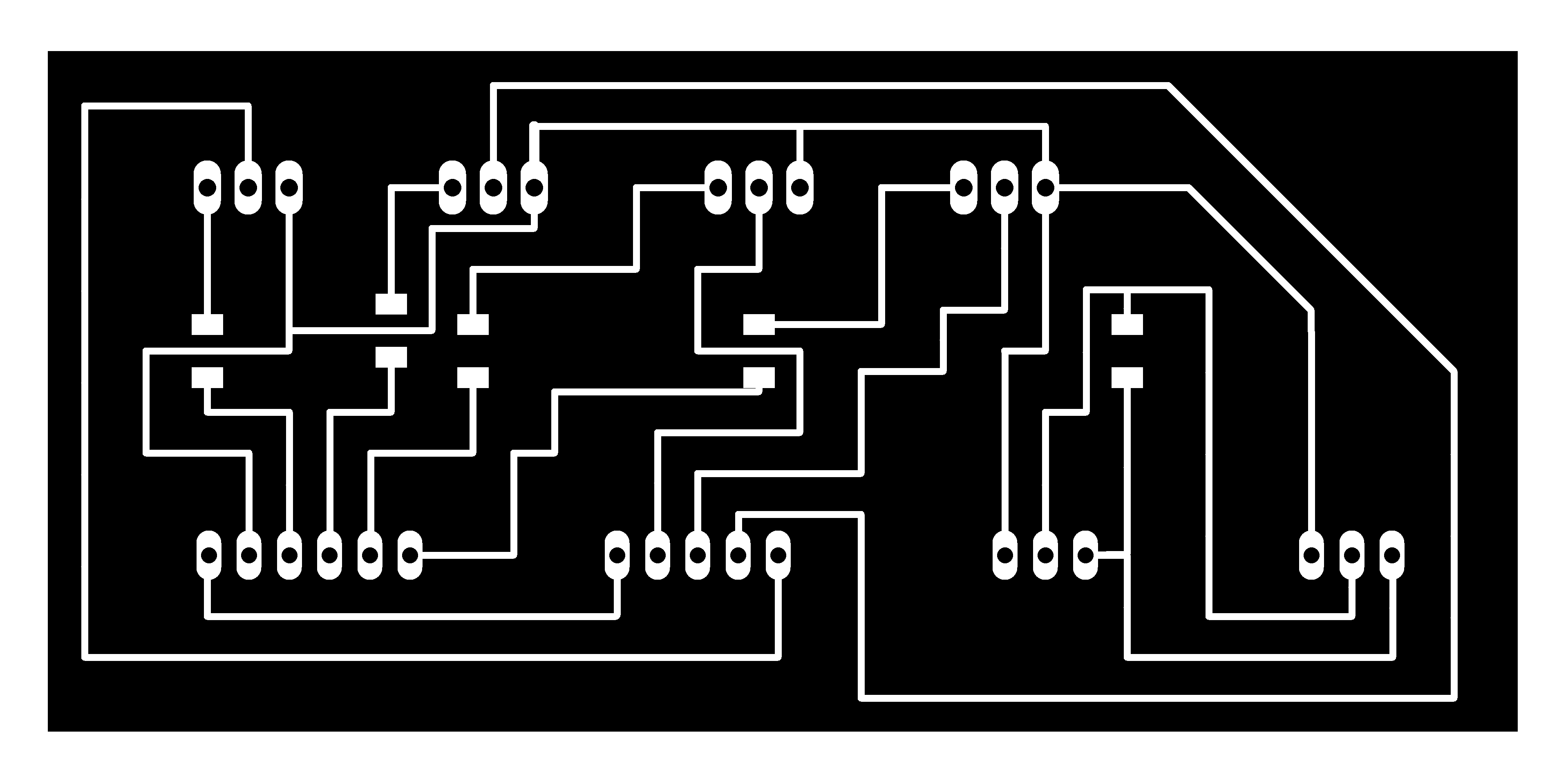
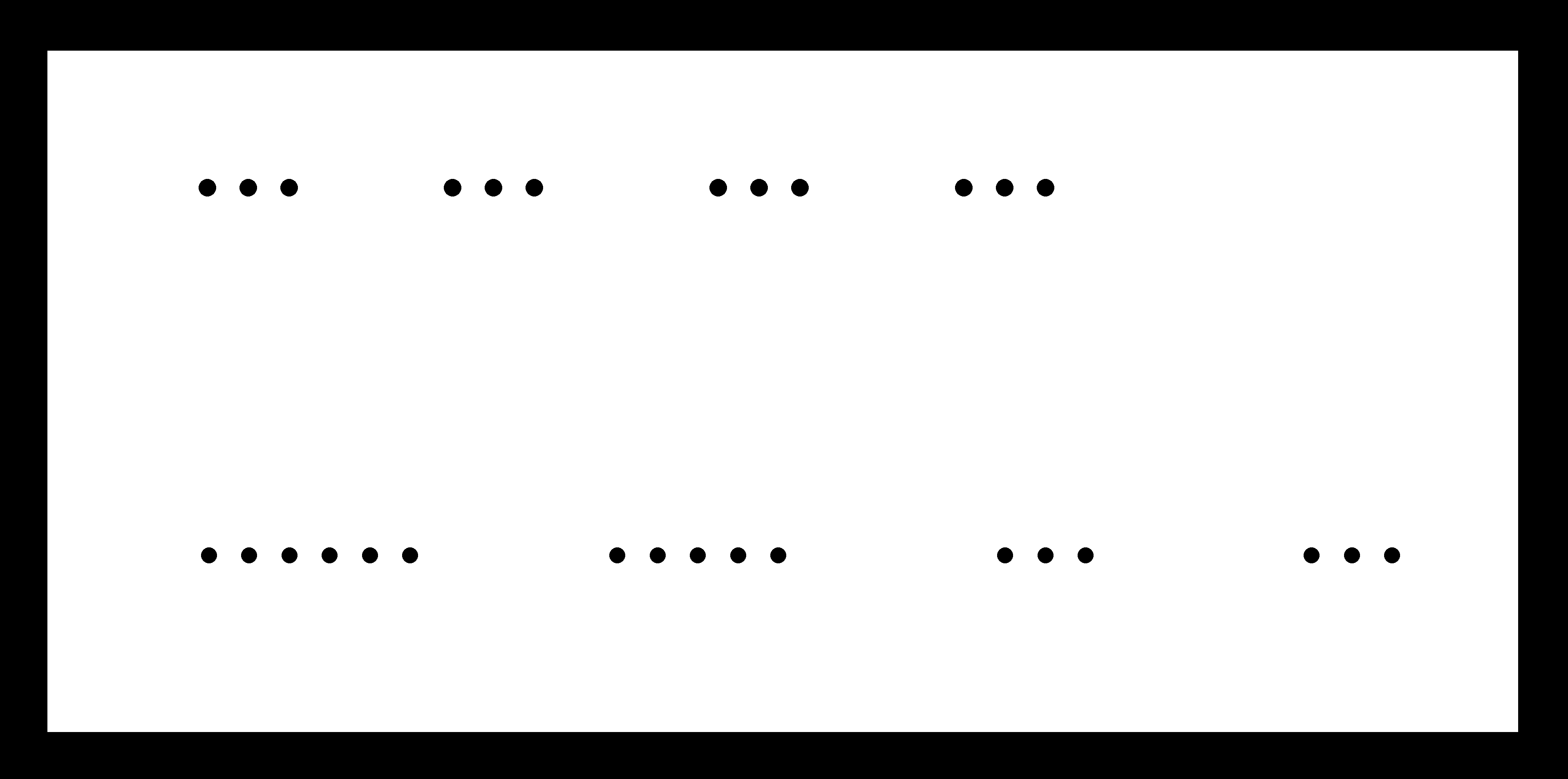
I draw the circuit in eagle and i exported the traces and the outline cut in PNG with 1000 dpi resolution.
Now i have to mill the board and solder and program it to test the circuit. I need to use a clamp programmer to program this board.
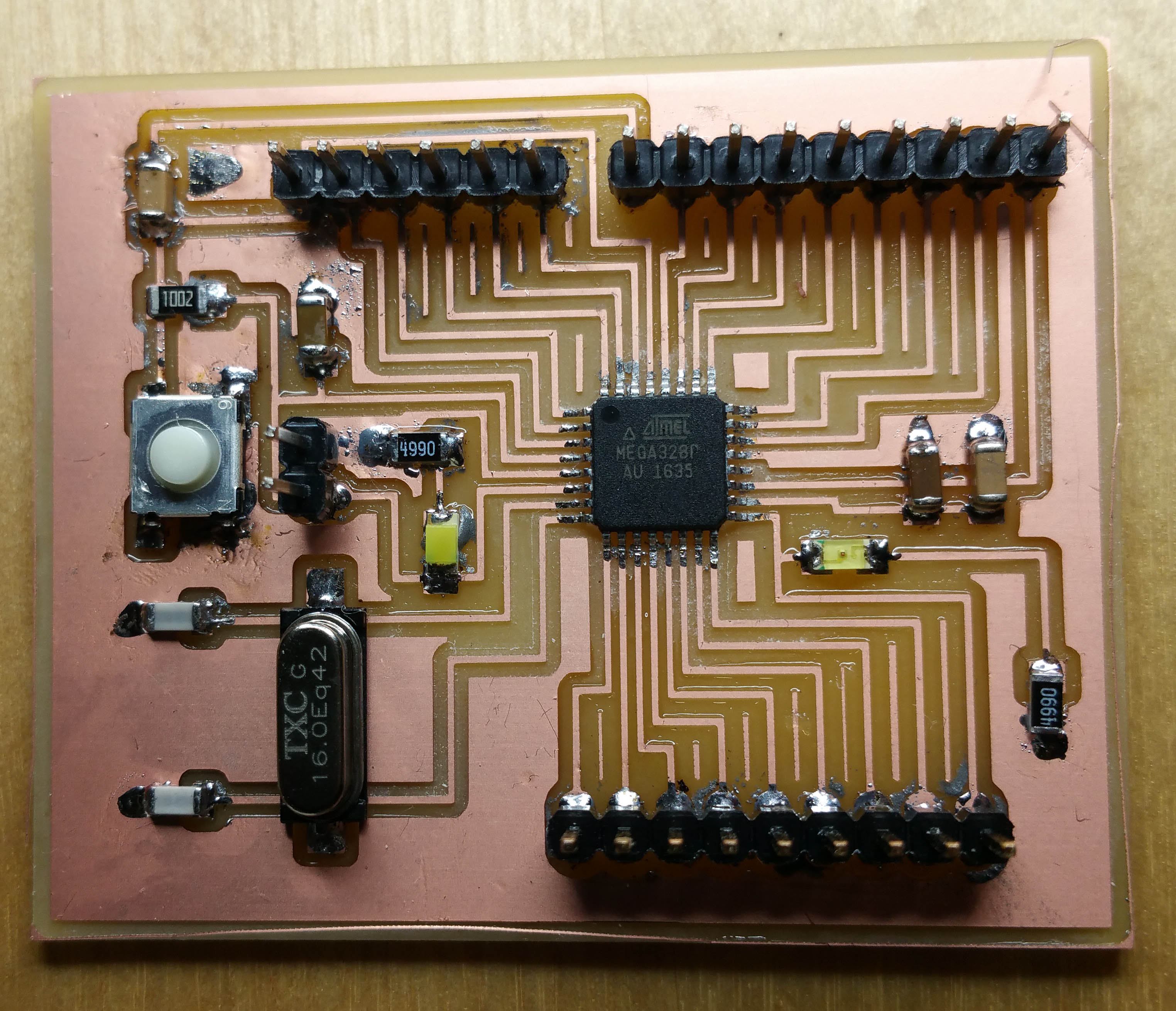
Step 5 : Programming my board with the satshakit fabuino
# Mill the board and solder components
Now i will use as arduino ISP programmer to programm my own board. I will mill the satshakit pcb and welding the components.
# Burning the bootloader with arduino as programmer
# Blink the satshakit
Step 6 : Result
VIDEO OF the prototype working with my own pcb board and a microcontroller.
Step 7 : Experiment Other Output Devices
Design a Machine
With Arduino at first, then a Atmel Attiny microncontroller
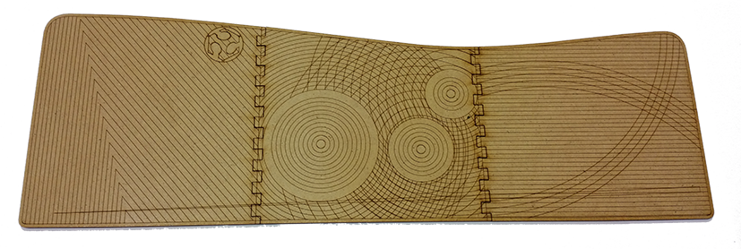
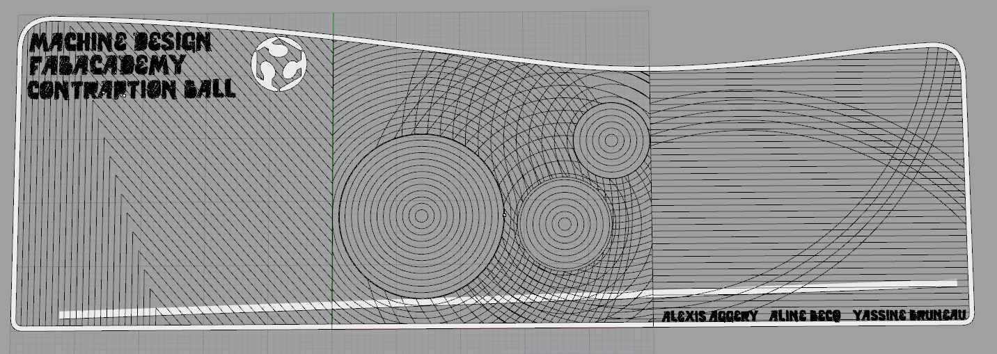
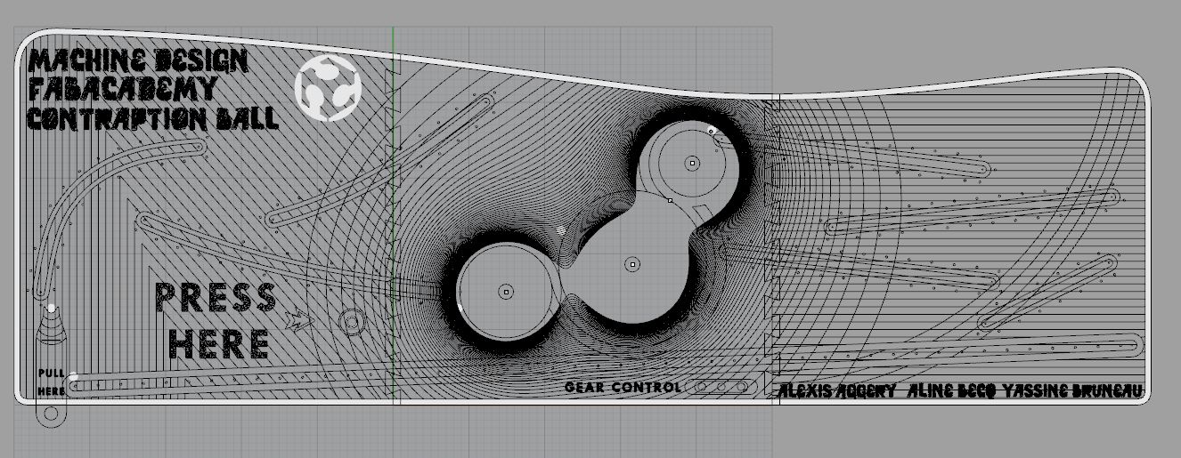
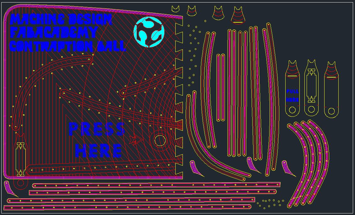
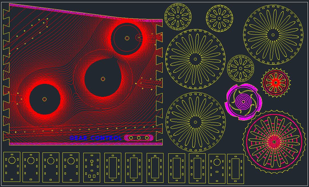
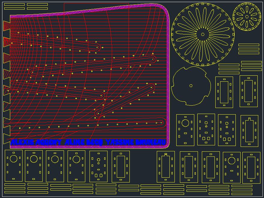
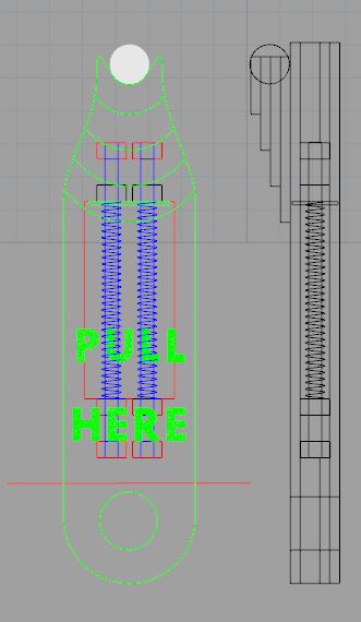
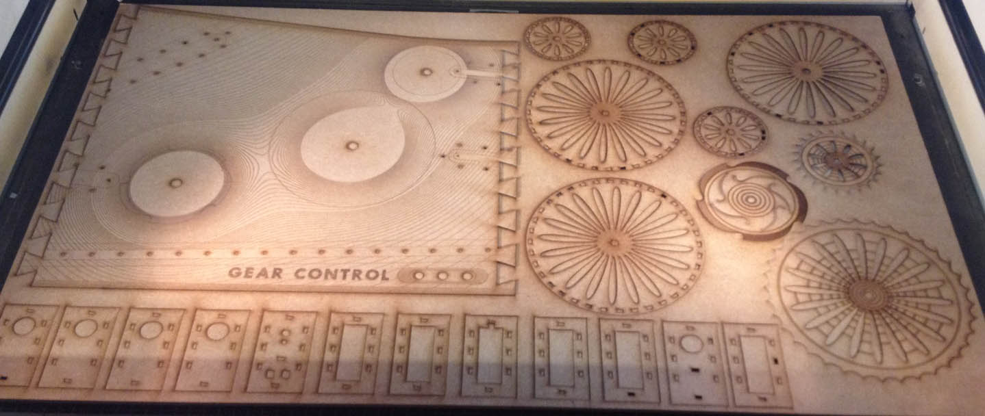
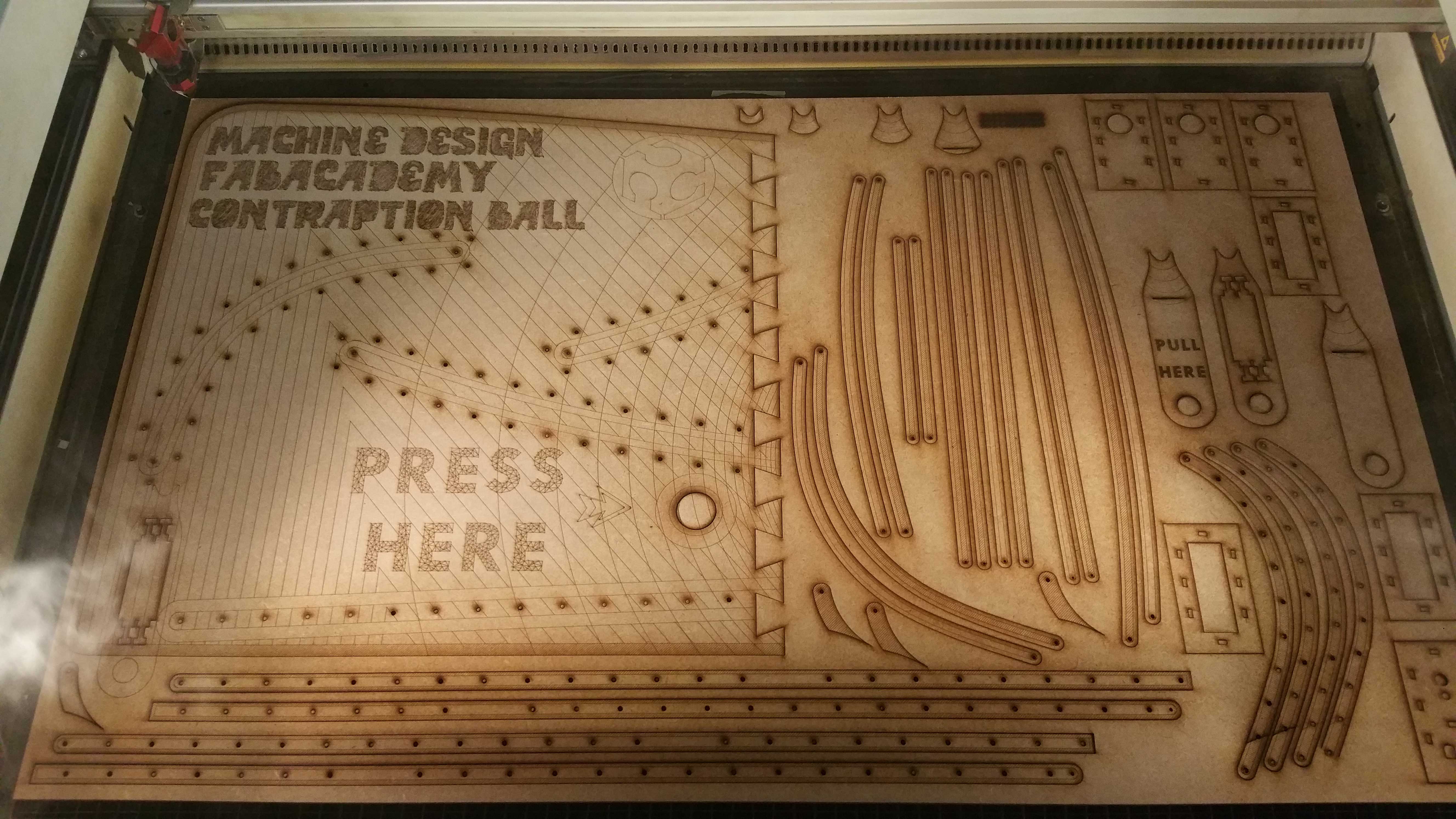
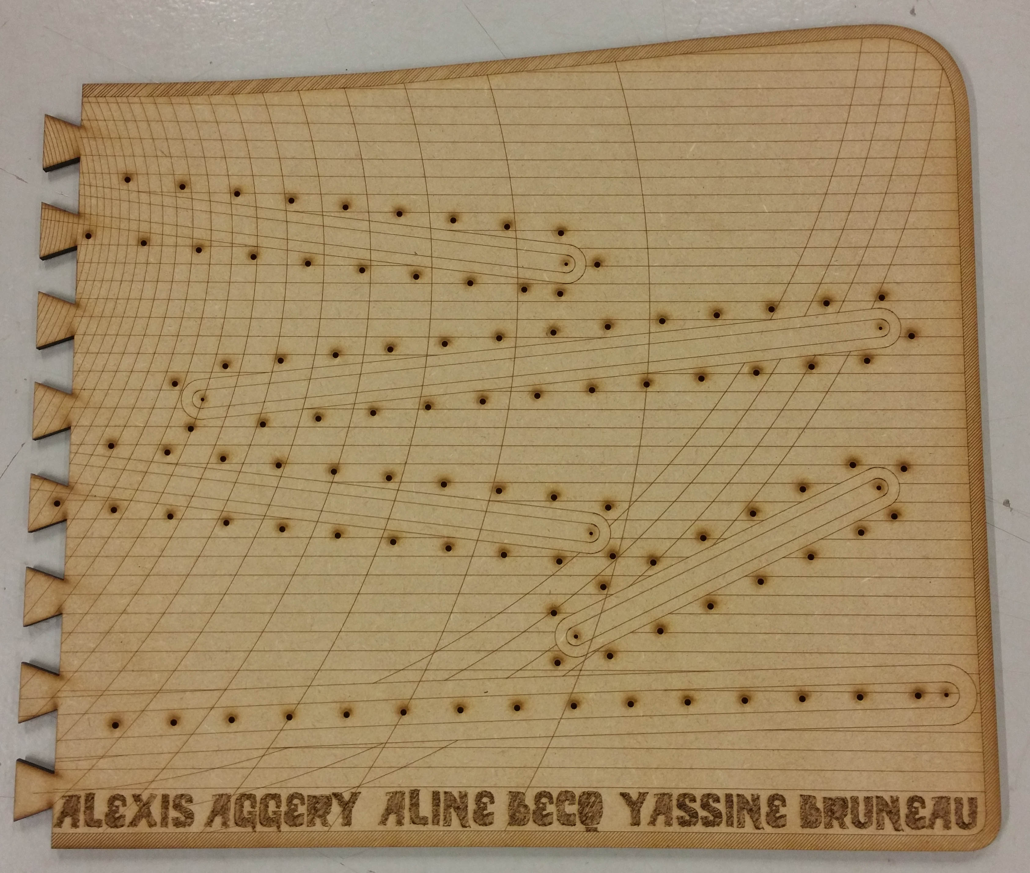
This 2 weeks we will try to design our OWN machine. This is a group project with Aline, Alexis and me. We divide the work in three part with a modularity concept. The project is a contraption divide in three differents module. In the first time we will design the machine, then we will prototype the electronic part to be more interactive. Let's go !
Step 1 : Draw the global design of the board
We decided to divide the final object in three equal part, the size of the part is a rectangle with 40 cm height and 50cm width. We decided to have an 45° angle table.
I will use rhinoceros 3D for this part and begin with a simple area. the design is inspired by the movement of the ball.
Step 2 : Lasercutting a small model to design the path of the ball
when this "contraptionball" machine will be finish correctly i will add a youtube video to finish this assignment.
Mold biomimmetic ondulations pattern
This 2 weeks i will try to mold something with a biomimetic design. Let's go !
Step 1 : First simple test
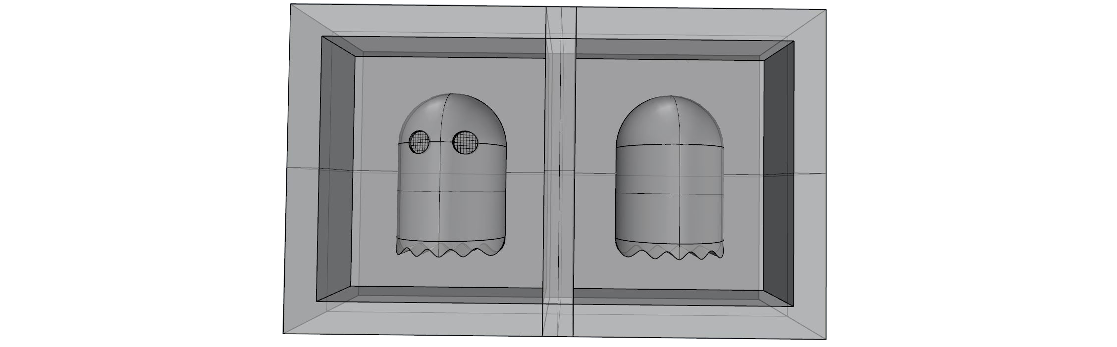
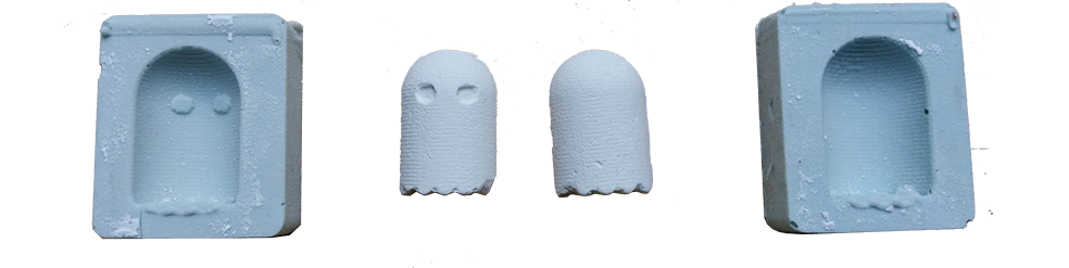
# Mold a ghost pacman
In order to quickly experiment with the molding techniques we decided to make first very simple tests. We chose to cast a figurine of the fantasy of the famous games Pac-man. We have modeled two complementary molds to reconstruct the overall geometry of the object.
# Milling the first prototype
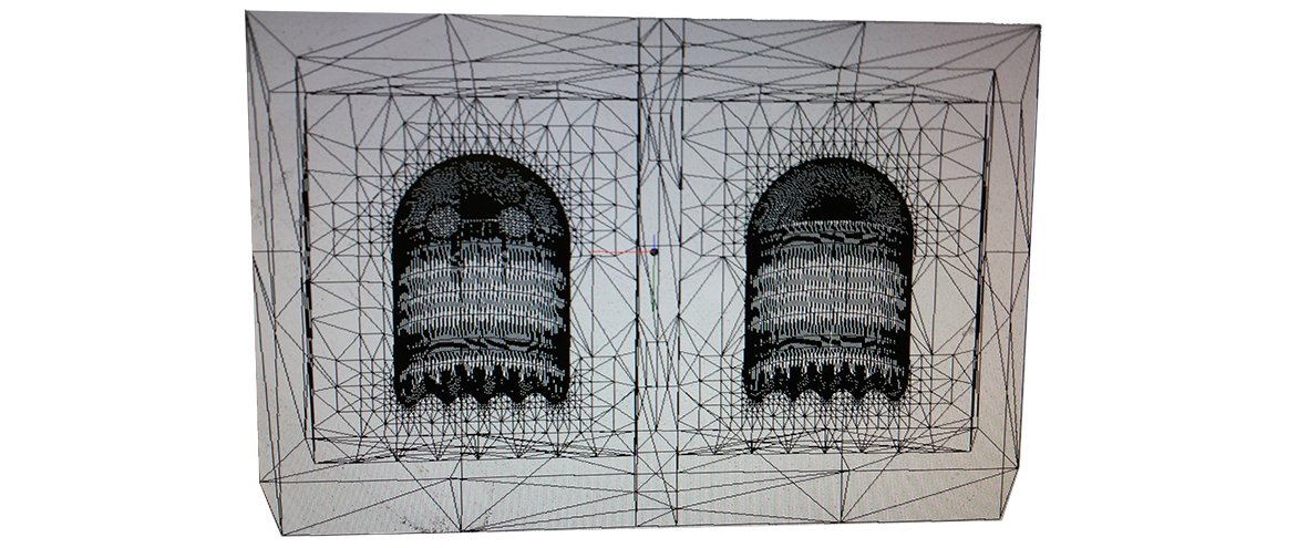
Once the milling machine has been calibrated and the file loaded into the Modela player 4. We have defined the milling milling parameters with a pass height of 1 mm. WE modelise this example in rhino and we export it in . STL
MODELA Player is a DTP software based on IGES, DXF and STL files from frequently used 3D CAD packages. The software is used to produce proportional 3D models, indicate the direction of the milling cutter and calculate the milling paths. MODELA Player imports a model (3D data) and calculates the path that the milling tool must follow (milling path). The software then drives the machine to mill the desired shape from a block of material.
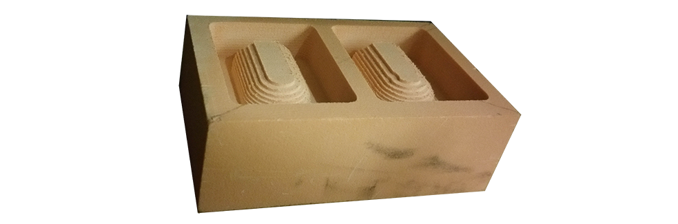
Once in the cnc milling machine, here is our pacman after a roughing-off with a cutter of 564 mm in diameter.
Here is the result after the first pass of roughing in a sanmodur brick.
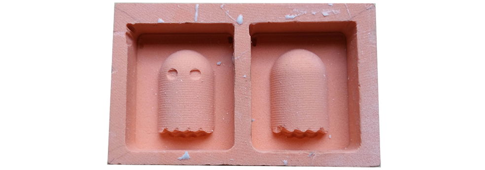
Here is the result after a finishing pass.
# Molding
Nous avons utilisé de la resine .... ?? avec du ...... dans une proportion de 5% du poinds. Le temps de sechage prends approximativement 24 h.
# Result
We did our first test with synthetic plaster. The object being very small, it has been difficult to remove it without slightly abrading its appearance because of the friability of the plaster.
Step 2 : Design something
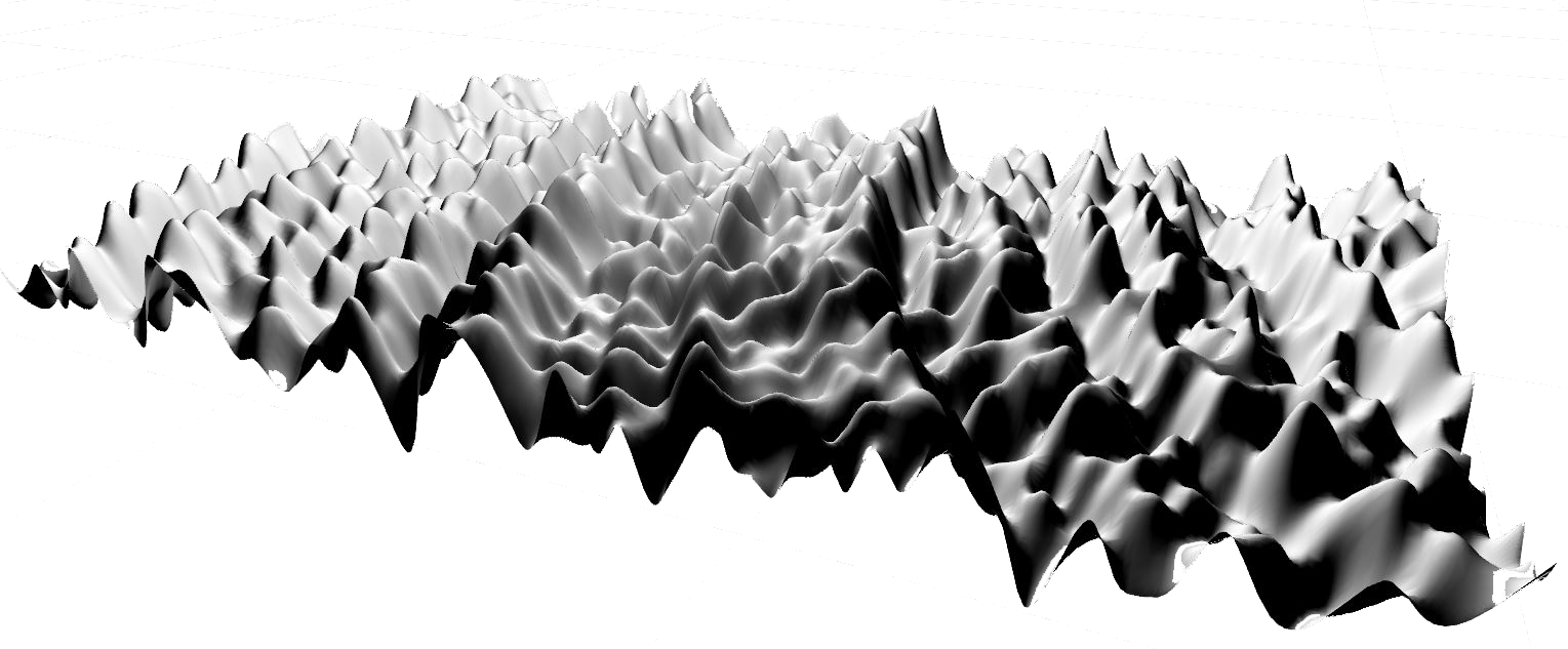
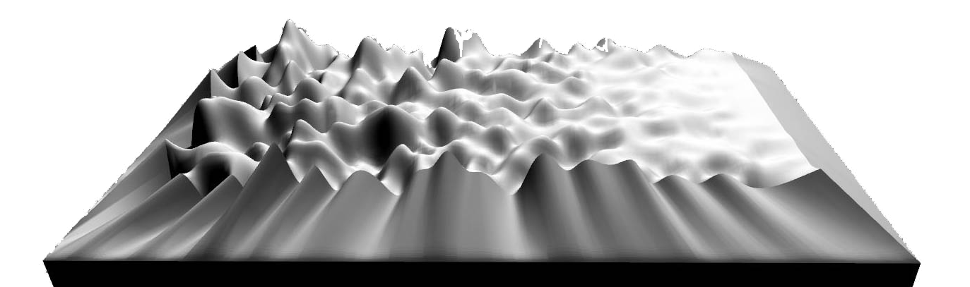
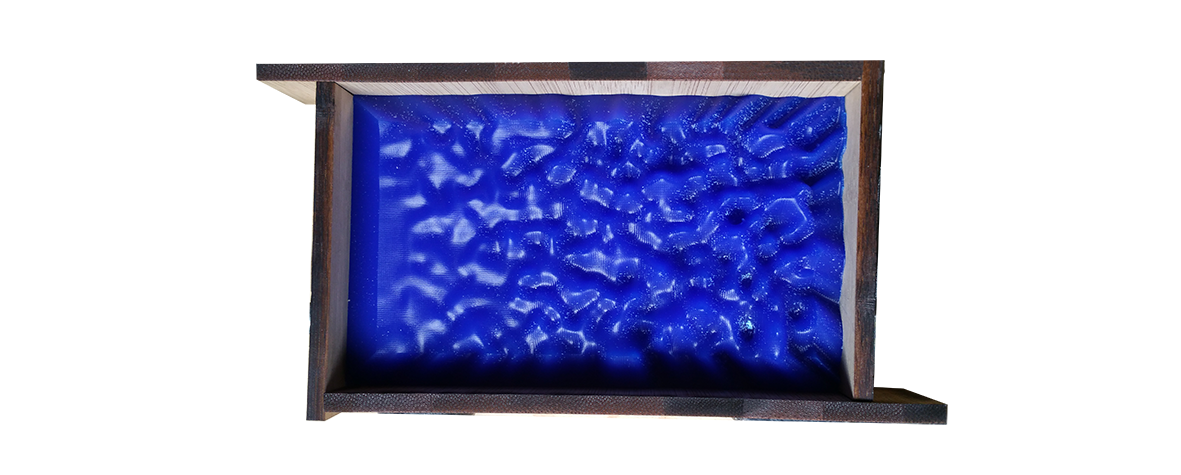
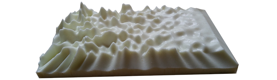
In order to explore to the maximum the formal potential and the smooth appearance that the molding techniques allow. I chose to work on the generation of complex geometries close to those that can be found in nature in the image of the disturbances that can be observed during the propagation of undulations on a water surface.
# First sketch
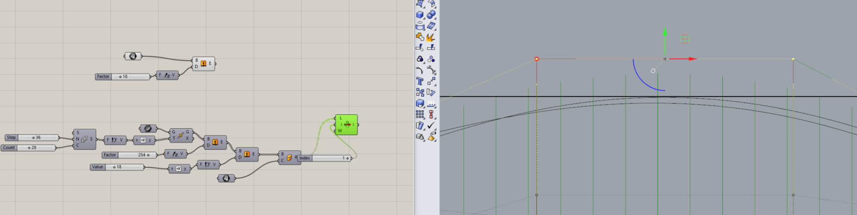
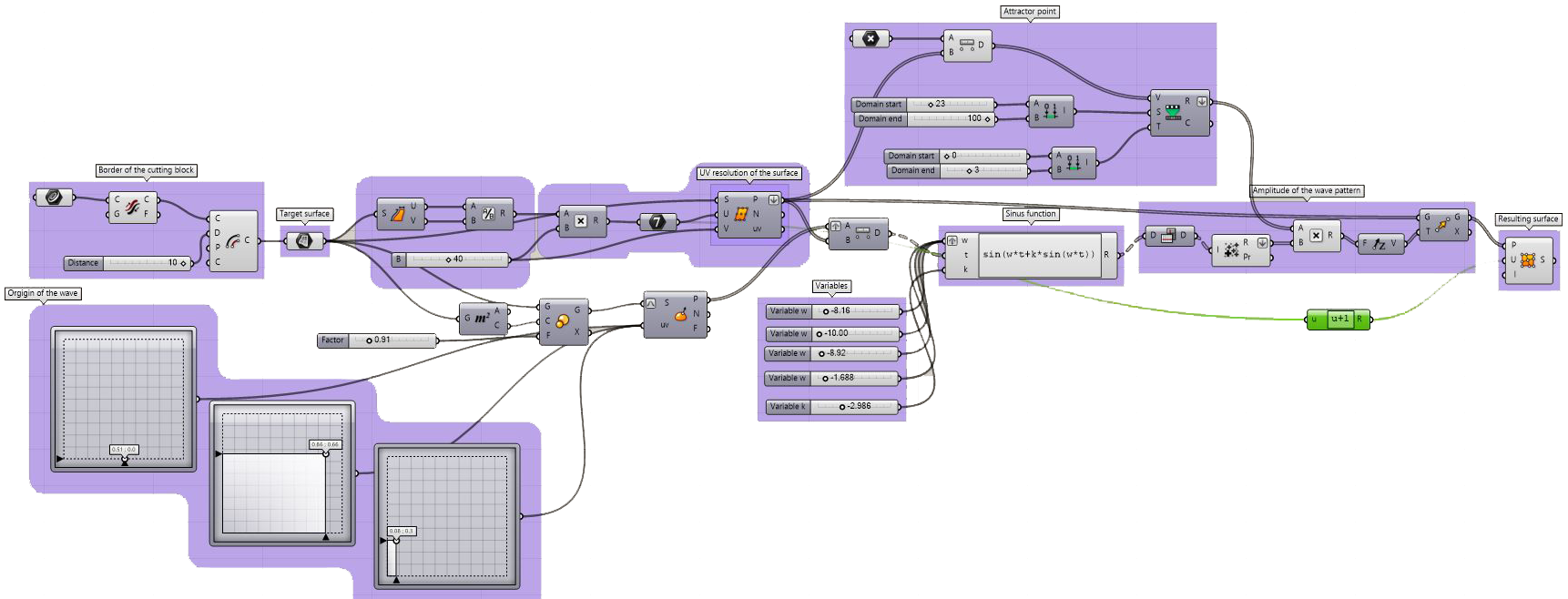
To begin this exploration, I chose a tutorial allowing to generate very complex patterns by sending sinusoids generating from sine and phase shift. This tutorial is available in the following link.
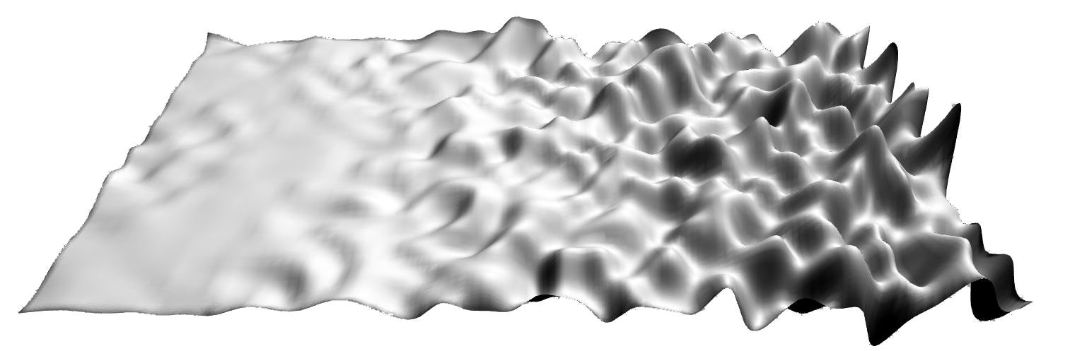
Here is a first overview of the surface generated from this script. Here is the link of the grasshopper script that I reconstituted from this video. It is from this base that I will define my final form.
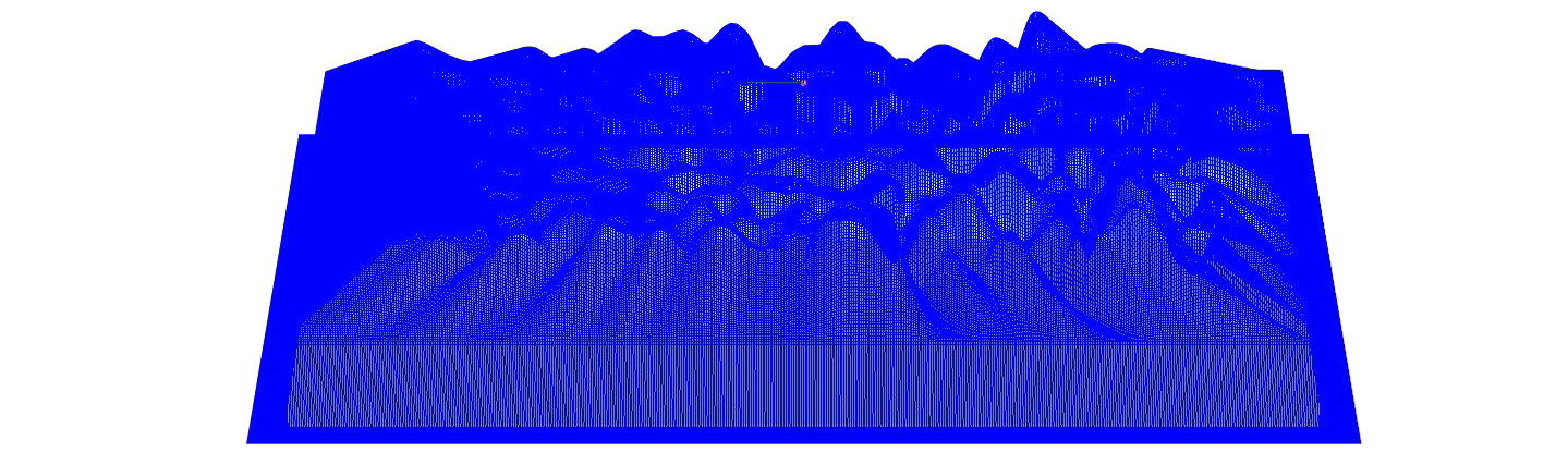
# Second sketch : Add an attractor point to transform the pattern
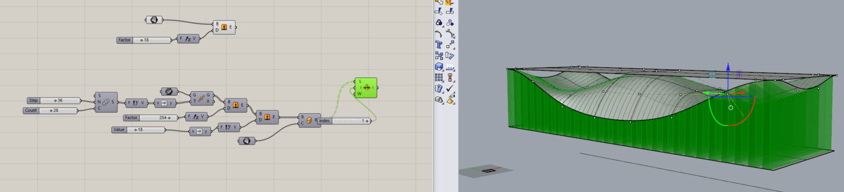
In order to improve the design, I decided to add a repulsion point as a continuous attenuation factor from a flat surface to an increasingly complex surface. Here is a short video that allows to follow the creation of the script and its influence on the form.
In this script we have defined a target surface from which we have defined a point grid whose resolution can be modulated in U and V. In the plane of this surface we have defined 3 points sources of undulations of which we Can change the coordinates of each. The distance between the sources and each of the points of our grid is defined as the antecedent of a sinus function. The amplitude of the three functions add up at each point to give a resultant amplitude in z. This resulting amplitude is in turn modulated by a factor which corresponds to the distance between this point and a defined repulse point. The set of resulting points defines a new Nurbs surface. In other words, we obtain a surface that evolves continuously from a plane surface to a choic surface generated by three identical sinusoidal waves but coming from 3 different sources.
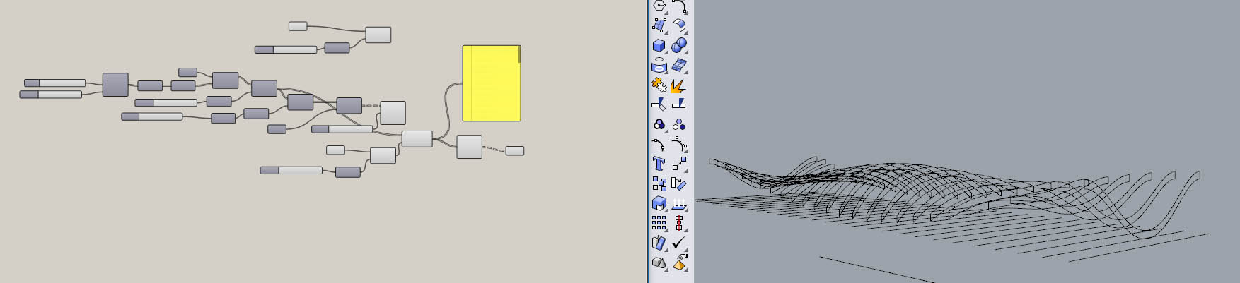
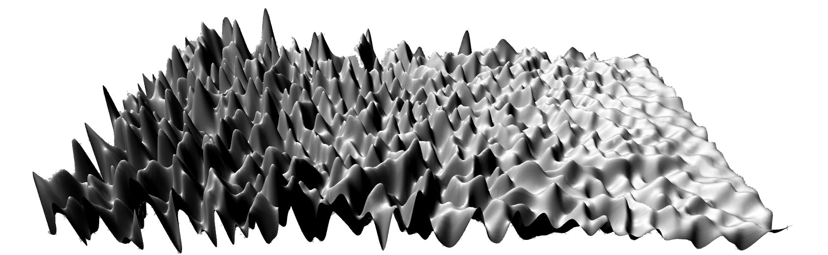
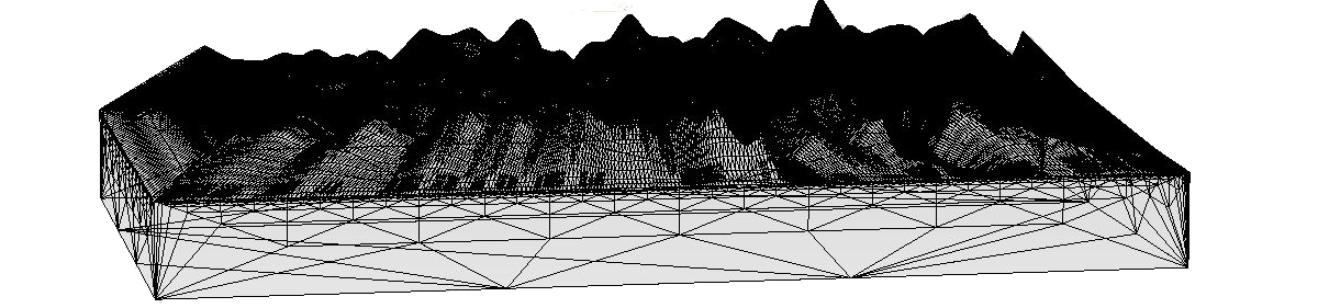
# Examples of Generated shapes
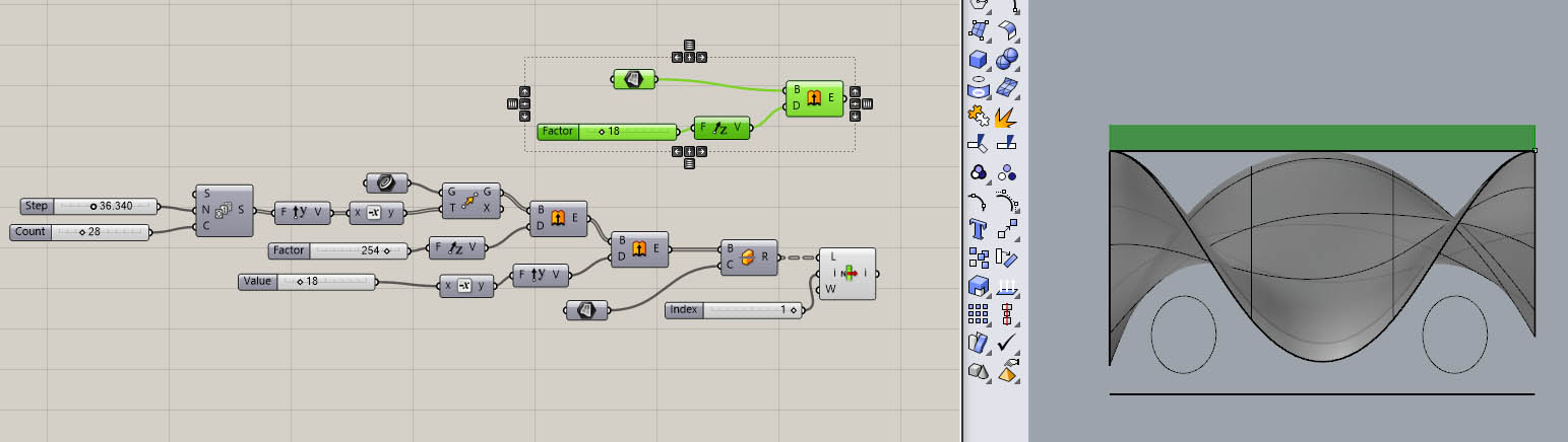
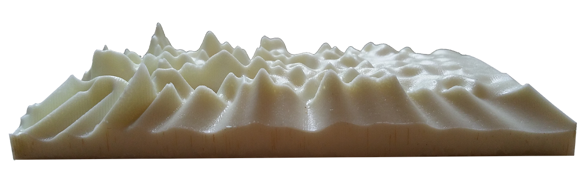
In this example, the passage from a rather flat surface to a more and more perturbed surface can be observed. I have defined an amplitude domain with a minum and a maximum.
To mount the evolution of the form I have considerably increased the maximum value of the domain of variation of the final amplitude of our sine function.
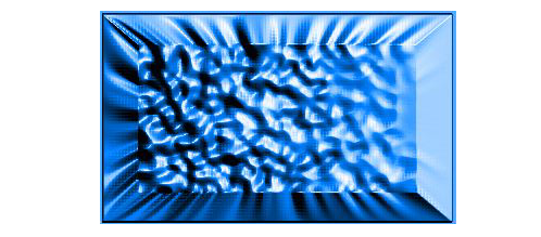
# How the sript transform the shape
This video shows the effect of the script on the shape on the surface when changing the parameters defined upstream.
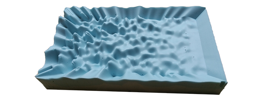
# Modelise a smooth object to Mold
We have an initial modeling resin block of 148.3x88.35x37.7 mm measured with a caliper. This is the strating point of the modelisation. In order to finish the file to send on the milling machine, we must make sure to have a 3D file whose volumes are closed. Then we can export to .STL
Step 3 : machine the mold
# Load the stl in the cnc machine
IMPORTANT : I have made a mistake when i generate the 3D. i exported directly in STL but it was more clever to transform my surface in mesh and decrease the number of polygons. When i realised this, it was to late... This is a very important point if we want mill complexes shapes !
# Generate the toolpath
My shape was very complex so it take three hours to generate the toolpath for the first path and aproximatively the same time to the second pass.
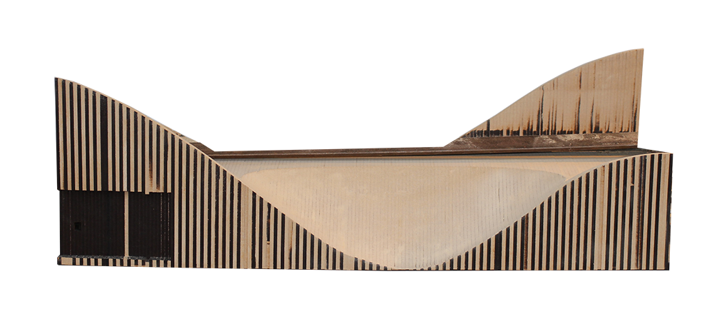
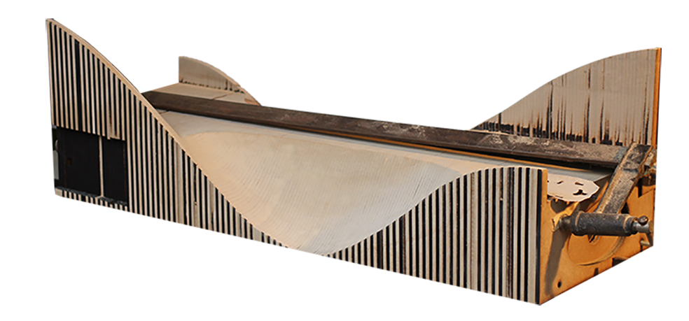
# Milling result
Here we have a picture of the result of the finishing milling pass. Same story for the milling job, it take 5 hours of milling for the first pass and approximatively 3h for the second pass.
Here is the simulation with the finishing pass with a linear milling in the X axis and a second in the Y axis.
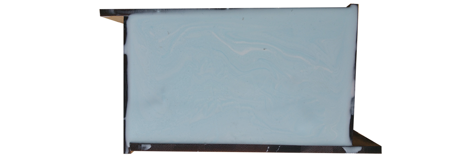
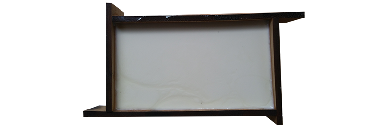
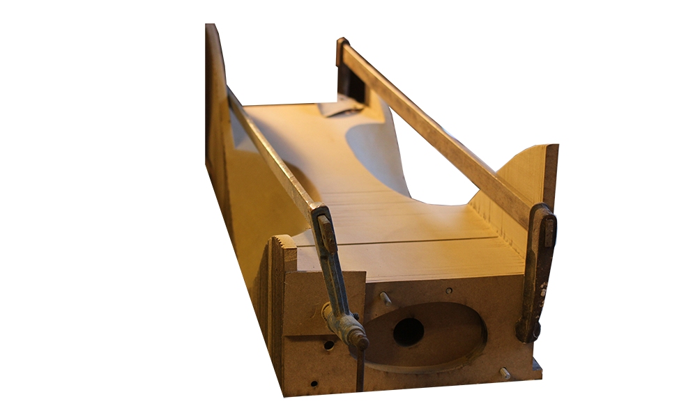
Step 3 : Molding the object
To optimize the size of the mold, I chose to mill the entire mold and to cut a laser box to finish the mold on the sides.
Now i will cast the polyurethane resine on the milled mold.
Now i will cast the polyurethane resine on the milled mold.
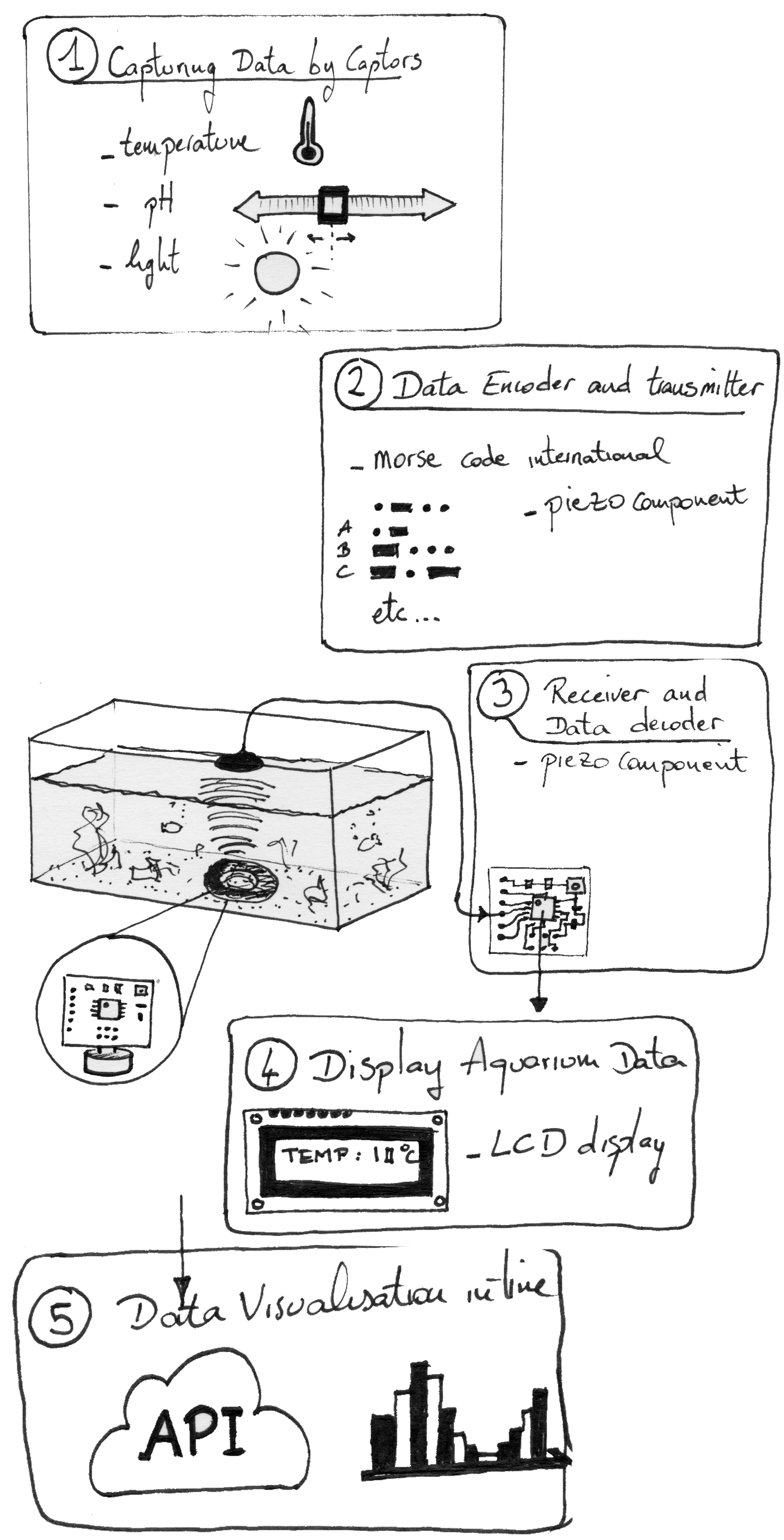
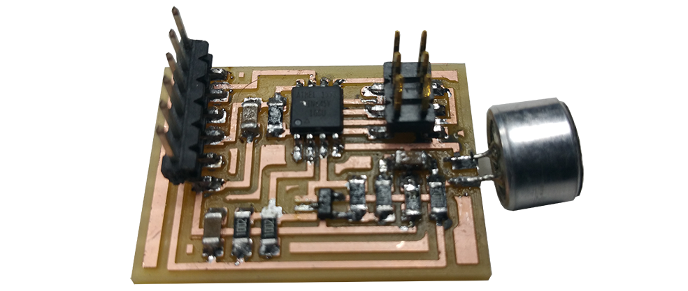
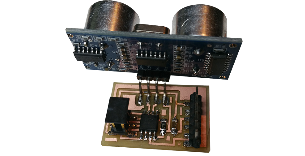
This week I will be particularly interested in capturing and broadcasting a sound signal. For my final project, I need to transmit information underwater. It seems that the sound is spreading particularly well under water. Acoustic waves appear to be the best means of transmission underwater.
In order to communicate underwater, for example in a simple aquarium, I decided to use sound waves for my final project. The sound spreads particularly well under water. In order to transmit the collected data (acidity, temperature, light, etc ...).
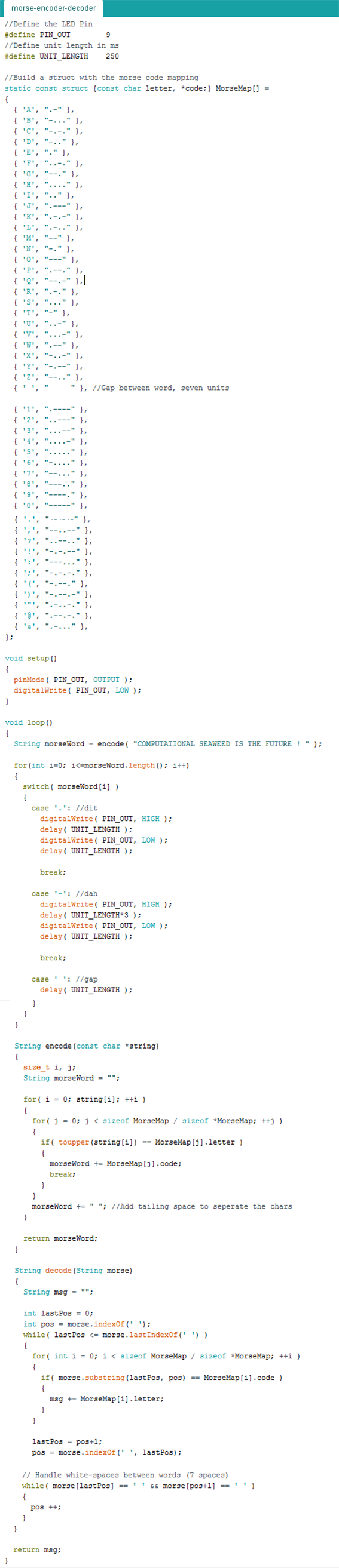
I decided to use the international Morse code to convey the value of the data captured.
# Arduino code
I found this code on the internet, I will improve it but it can be the code base of the communication system of my final project.
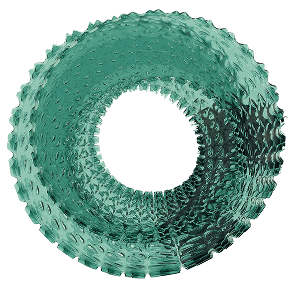
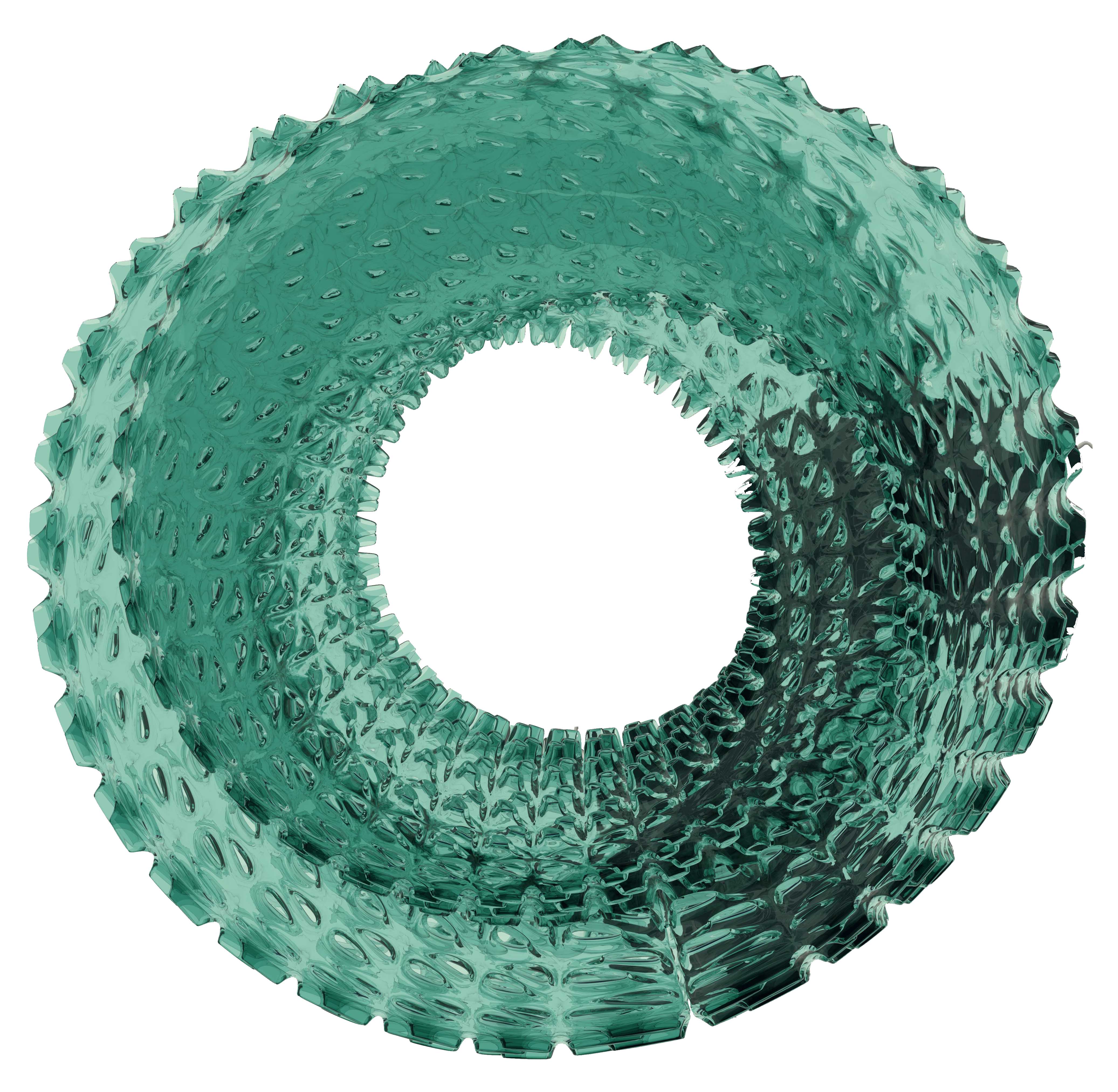
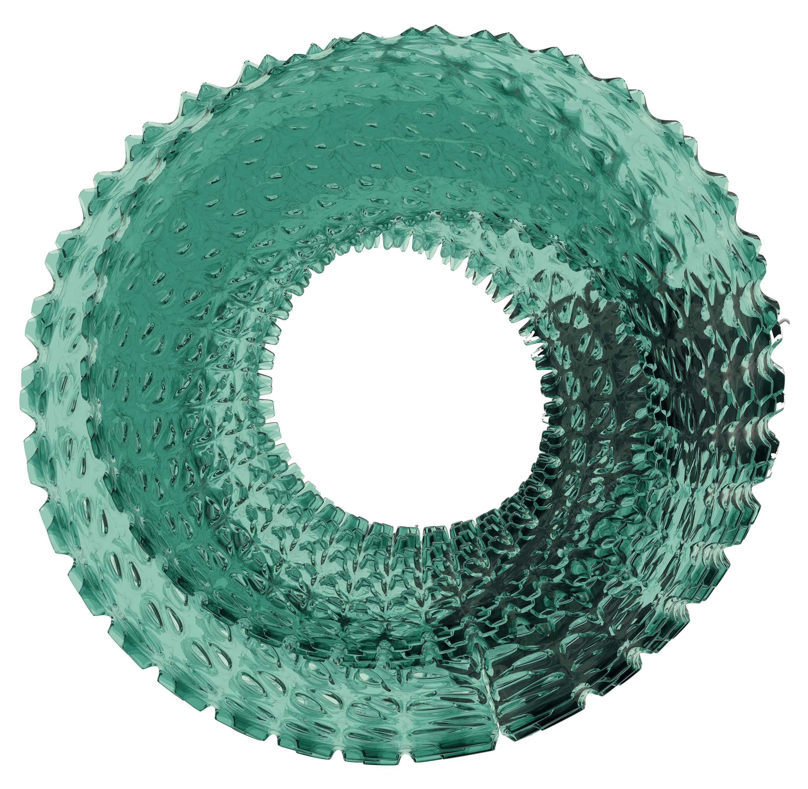
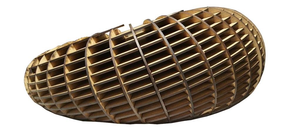
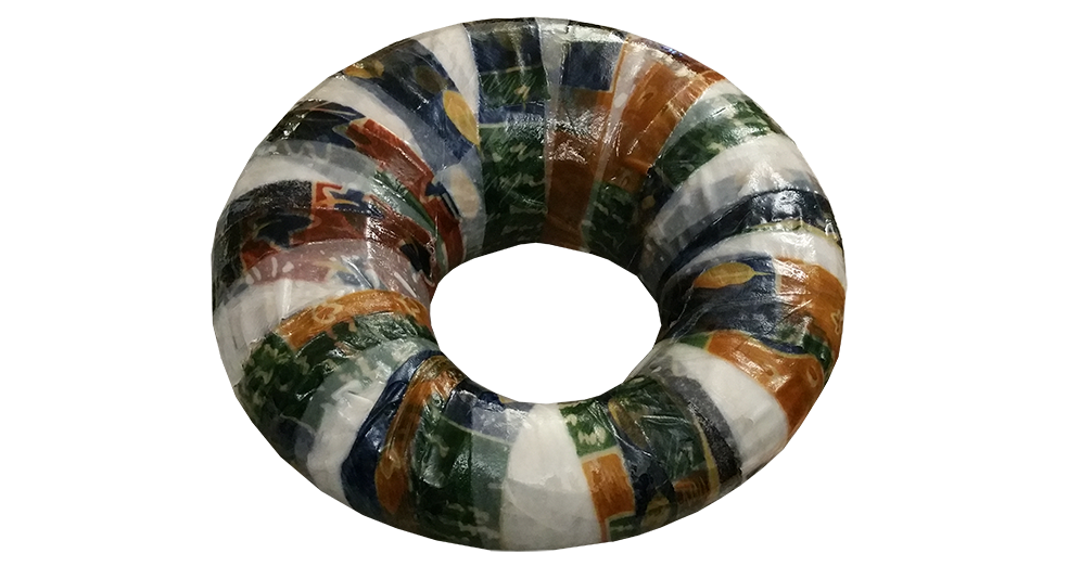
This week, i am interested to experiment waterproof composite.
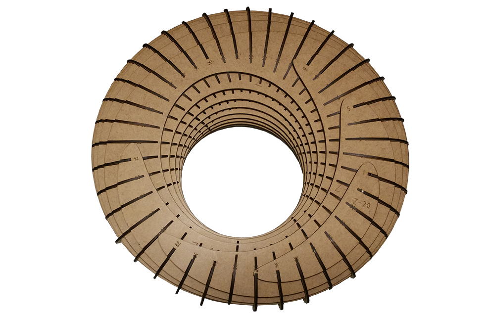
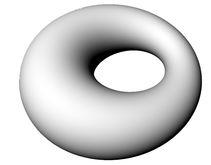
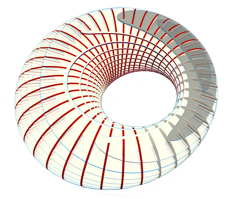
Step 1 : Modelise a tore with an attractor point
# Modelisation
In this exercise, I tried to model the simplest and smallest possible submersible to do this experimentation. I chose this form of torus for its ease of implementation for the molding of composite. A maximum curvature is thus obtained with a minimum of difficulty in applying the composite.
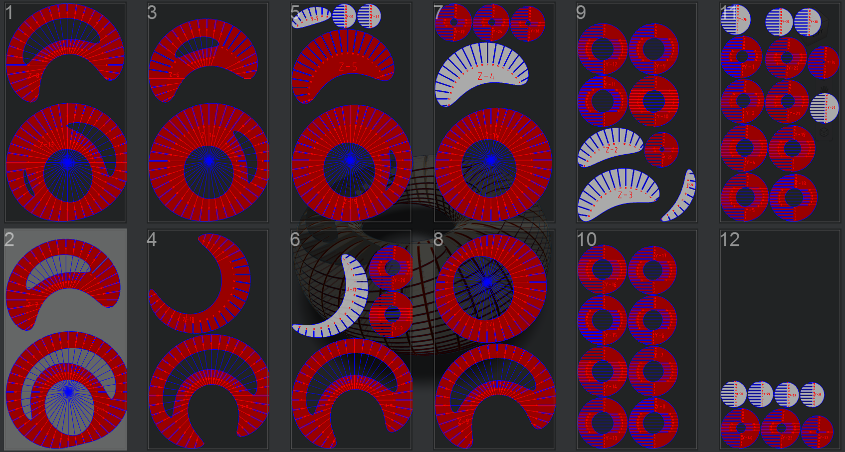
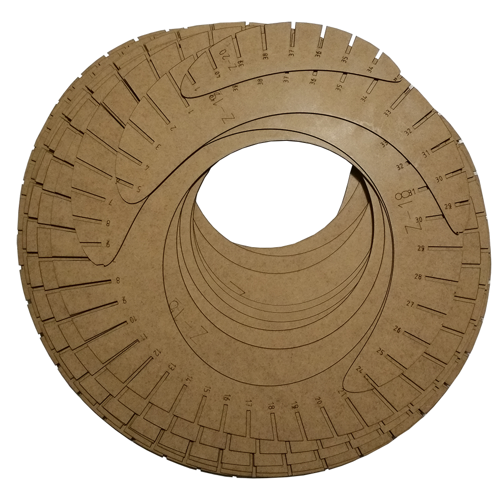
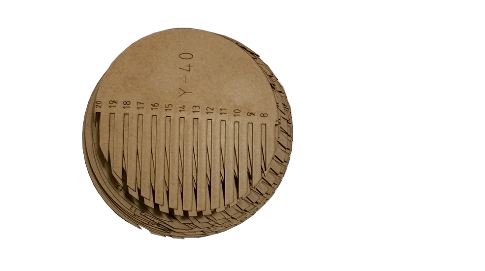
In order to generate a pressfit kit to create the positive mold of our composite I used 123D make in order to generate mold assemblies and cutting files. The diameter of the torus is about 40 cm.
In the Autocad software, I modified the width of the slots for the pressfit kit. Given the complexity of the assembly I took a margin of 10 percent. The cutting material is medium thickness 3mm. The width of the slot is therefore about 3.3mm.
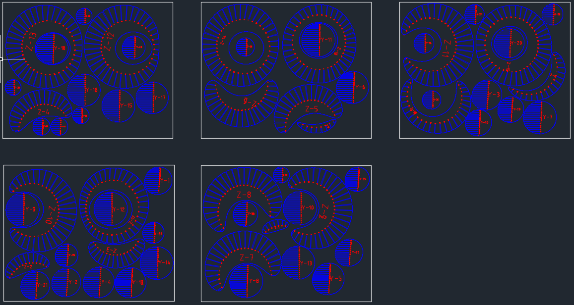
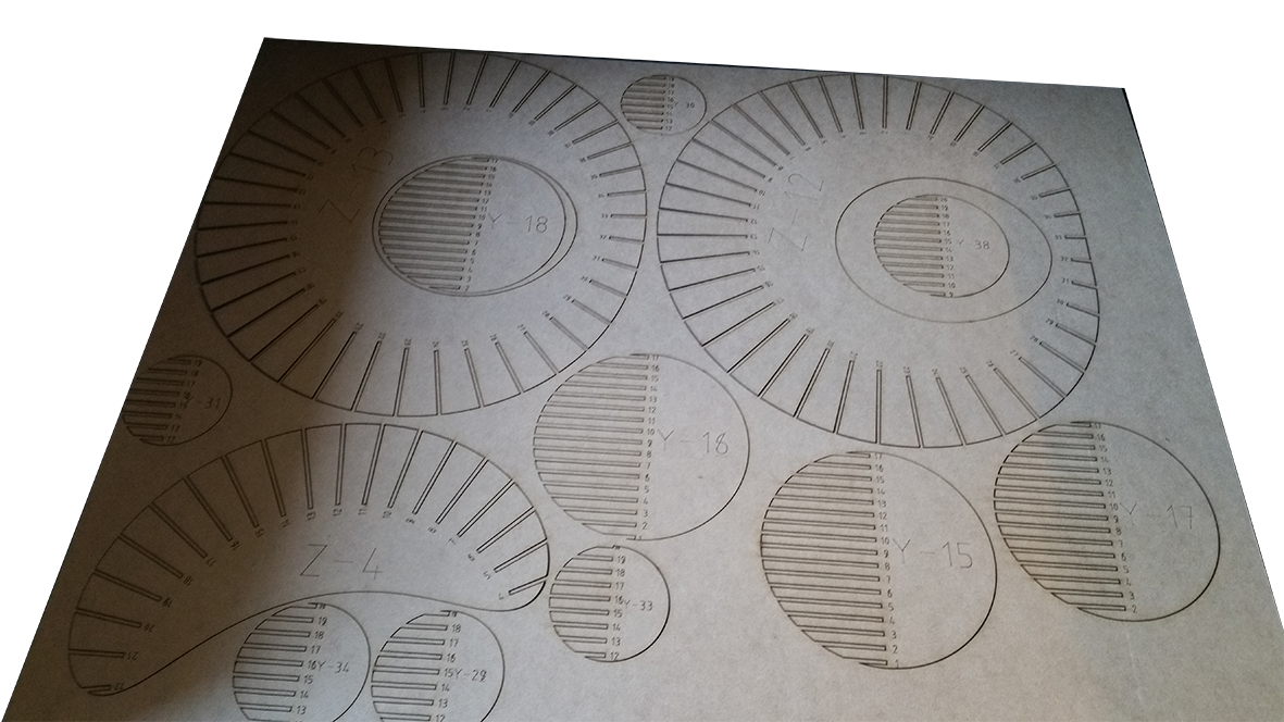
# Lasercutting
I used 3mm mdf boards in order to cut the object. The file is composed of blue lines that are programmed to cut the mdf with a power of 60 percent of the laser, and red lines to trace the markings to facilitate assembly.
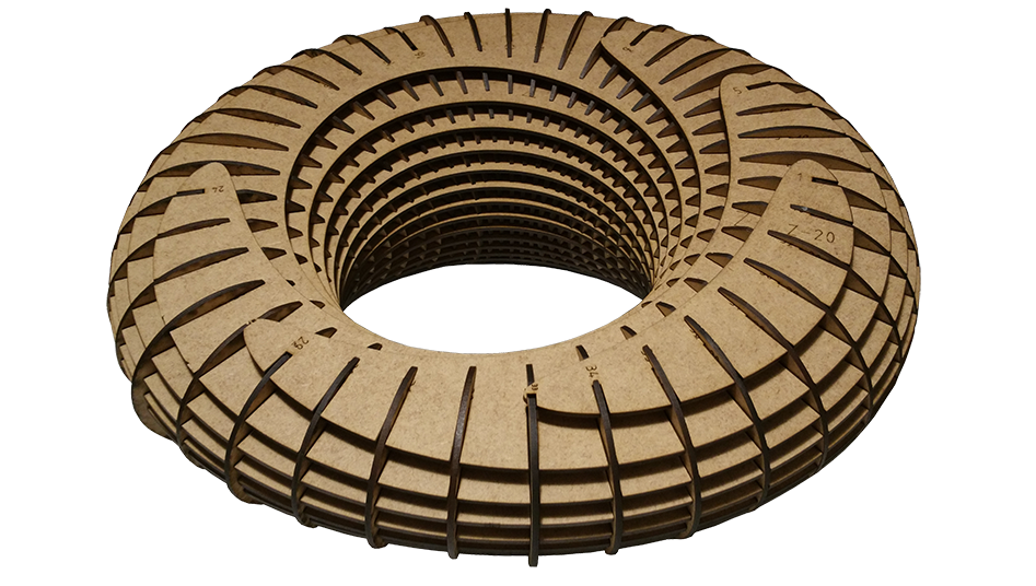
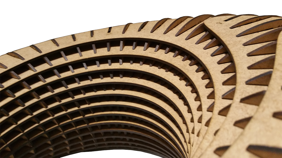
Step 4 : Assembly
# cutted parts
# Result
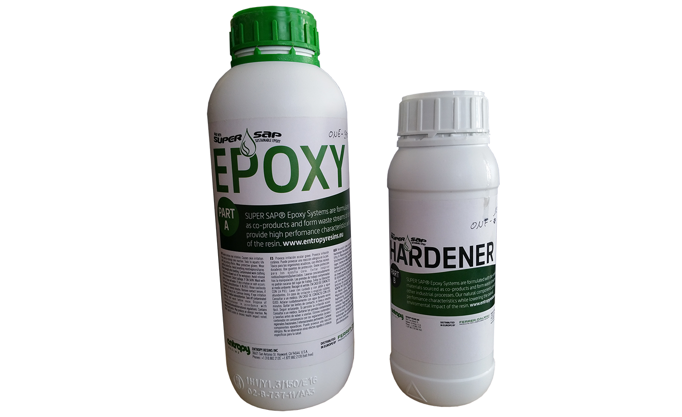
Step 5 : Read the resin data sheet
# Information about the resin
You can download HERE to read the datasheet of the SUPER SAP Epoxysystems resin
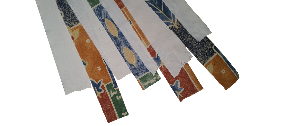
Step 6 : Make the composite
# Prepare the cotton fiber strips
In order to obtain the smoothest possible result, I decided to cut out long strips of cotton which will be easier to imprinier of resin and easier to apply on the geometry of the tor like a bandage.
I chose bright colors with an altrance of colored and white strips to give a more sympathetic appearance to our composite torus. The cotton fiber bands have been ironed beforehand in order to minimize the apparent folds.
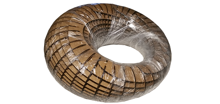
# Prepare a smooth surface to apply the resin
In order to avoid feeling the internal structure of the mold and that the epoxy does not stick too strongly on our mold, we covered the mold of food plastic film.
# Mixing resin and epoxy
The mixture between the resin and the epoxy is 44% by weight for the hardener. Once the two liquid in the same recipent, it is necessary to apply immadiately because it takes only 20 minutes for our mixture to stick already very strongly ..
# Make the composite
Networking and Communications
This week I will be particularly interested in capturing and broadcasting a sound signal. For my final project, I need to transmit information underwater. It seems that the sound is spreading particularly well under water. Acoustic waves appear to be the best means of transmission underwater.
Step 1 : Defining the concepts
# What is a bus ?
A bus is a link shared by devices whose characteristics and number are not fixed in advance.
# What is a serial communication ?
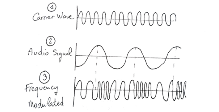
Segment transmission is a data transmission modality in which the elements succeed each other on a single path between two points. It is involved in parallel transmission, which simultaneously transmits information elements over several channels. In general, the serial digital transmission devices distinguish two signals corresponding to 1 and 0. The signal element is one bit. The transmission paths do not allow the detection of absolute levels. A carrier frequency modulation is transmitted.
# What is a Carrier wave and FM radio Wave ?
A carrier wave is a waveform which is modulated by an input signal for the purpose of carrying information. Frequency modulation and amplitude modulation are common modes of modulation of the carrier.
# What is a Bauds ?
The baud is a unit of modulation speed in digital transmission. The modulation speed of a signal is equal to the inverse of the duration in seconds of the shortest element of the signal or of the unit interval in a digital signal composed of a signal element of constant duration. The term Baud comes from the patronym of Emile Baudot, the inventor of the Baudot code used in telegraphy.
# What is a communication protocol ?
A communication protocol is a specification of several rules for a particular type of communication.
# What is I²C ?
Inter-integrated Circuit (I²C) is a half duplex bidirectional synchronous serial bus, or several master or slave devices can be connected to the bus.
It is an interesting protocol because it is generally used to communicate between the components on the motherboards and in any integrated system.
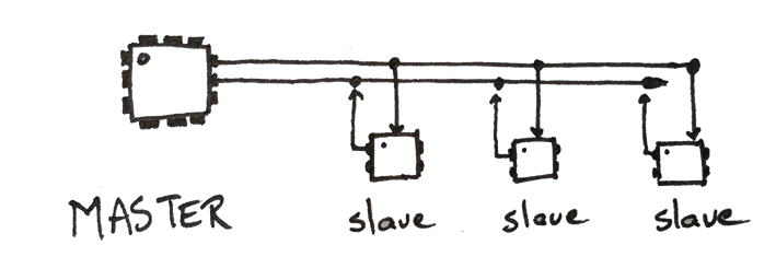
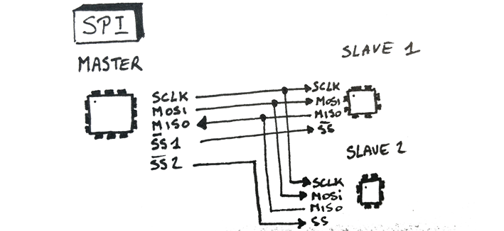
# What is a SPI link ?
A Serial Peripheral Interface (SPI) is a synchronous serial data bus that operates in full-duplex mode. The circuits communicate in a master-slave scheme, where the master controls the communication. Several slaves can coexist on the same bus, in this case, the destination is selected by a dedicated line between the master and slave called Slave Select (SS).
To use an arduino card as a master card, we need to use a library called SPI library.SPI library
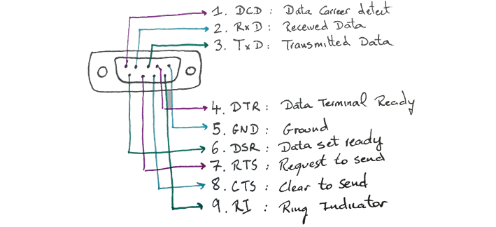
# What is RS - 232 ?
RS - 232 is a protocol that is a serial communication channel. Asynchronous and duplex between two devices.
Step 2 : Experimenting I²C betweens arduinos
# Tutorial
To experiment with the exchange of data by I²C protocol, I recommend tutorial.
The description is very precise and it is easy to achieve.
# Video
Step 3 : Experimenting I²C with arduinos and satshakit
# Video
Step 4 : Experimenting I²C between 2 satshakit
# Video
Step 5 : Use a logic Analyser to Visualize the data exchanged by I²C protocol
# Why use a logical analyzer ?
A logic analyzer is an electronic instrument that captures and displays multiple signals from a digital system or digital circuit. A logic analyzer may convert the captured data into timing diagrams, protocol decodes, state machine traces, assembly language, or may correlate assembly with source-level software. Now that we know how to exchange information between two electronic cards with the i2C protocol. It is interesting to visualize the exchange of data that occurs between the master and slave boards. The master card sends at each interval of a duration of 2 seconds the value 0 then the value 1. The process repeats loop thereafter. Thanks to this logic analyzer we will be able to visualize these values over time.
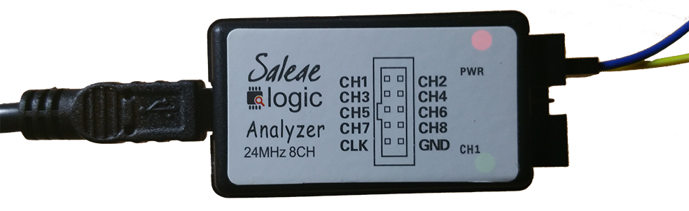
# Material
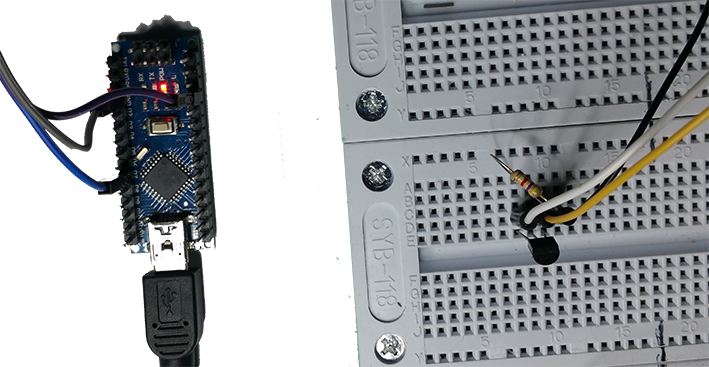
I bought a small digital logic analyzer of Chinese manufacture for 5 euros. It works perfectly and is available here.. I allows the signals to be sent to 8 channels. Which is largely enough for most operations and delays the purchase of a more expensive digital oscilloscope. It is visible in the picture below.
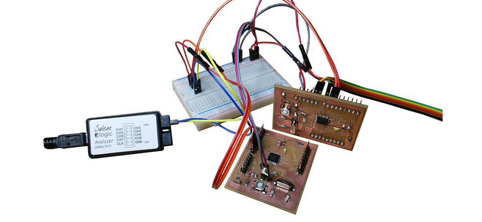
# Tutorial
So I use a breadboard to connect logic analyzer chain 1 on the SCL connection, and string 2 on the SDA connection by simple connecting cables. The lorgic analyzer is then connected to the computer to power it and send the data to be visualized.
For more information and instructions on this digital analyzer, I advise you to look at this tutorial which shows very effectively how to use it on a SPI, I²C and UART connection.
# Software
The software used in this tutorial is the software saleae. It is free and very easy to take in hand.
You can then save the signal to be exchanged between the two cards, which can be very useful.
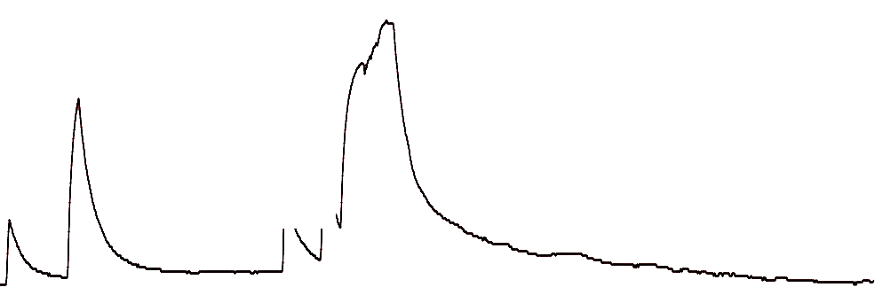
# Result
I recorded the signal for 10 seconds. As can be seen there is a data transfer every two seconds on the SDA connection of a digit (0 or 1 as the case may be) and no signal on the SLC connection, which is normal because the program does not order any Return data.
This week I will try to experiment the interactions between Raspberry pi, arduino and processing.
Step 1 : Discover Processing
# What is processing ?
Processing is an open source computer programming language and integrated development environment (IDE) built for the electronic arts,
new media art, and visual design communities with the purpose of teaching the fundamentals of computer programming in a visual context, and to serve as the foundation for electronic sketchbooks.
Processing has a large community of users around the world. Some agree to share their sketches on a platform called openprocessing.org.
It is an ideal way to discover graphic programming potential with processing.
# Make your first sketch
When you open processing and you press the "play" button you get a simple square gray color.
Change the size of the windows
Now you will write the following command: size (400, 500);
Click play, and you will get this:
You learned how give a size in pixel to a window.
Give a background color to this window.
In order to do this, you just need to add the following command to your sketch : background(0, 0, 0); Click play, and you will get this:
Change the background color you want.
the command background(r, v, b) use the RVB coulour code. So you can click here to choose the colour wou yant copy the rvb coordinates and write into your sketch.
For exemple if i want a blue Cyan R=1 , V= 237 , B= 254. So i write the folowing command : background(1, 237, 254); Click play, and you will get this:
make a rectangle inside the window
In order to do this, you just need to add the following command to your sketch : rect(20, 20, 300,600); Click play, and you will get this:
Result of your fist sketch
This is simple but i am sure you love it already =) !
# Learn main geometry functions
point()
A point is composed by one couple of coordinates (x , y). So it is logical that tha command point is writed like this : point(x, y)
line()
A line is a junction between 2 points distincts wich their own coordinates A(Xa,Ya) and B(Xb,Yb). So the command line is writed like this :
line(Xa,Ya,Xb,Yb)
triangle()
quad()
rect()
# Learn colours
Transparency
# Setup and draw functions
Setup()
The setup () function concerns everything that is going to happen at the time of the execution of the program
Draw()
The draw function is repeated in a loop at a rate defined by an instruction: framerate ()
# Conditional and iterative functions
Conditional structures are tests that determine whether one or more conditions are met and then perform an action as a result of the test result.
If()
If () makes it possible to determine whether an action is true or false and then, if necessary, to execute a sequence of instructions
else()
We can complete the code that precedes with a bifurcation with the expression else, which will propose an alernative code to execute if the condition is not validated
else if()
The command else if() will make it possible to verify a continuation of verification: Si ... Otherwise .... Otherwise .....
for()
while()
The iterative loop commanded by the while () command instructs the execution of the statement as long as the condition is true.
switch()
Switch () allows to compare a large number of values to the same variable
continue and break
Continue lets you skip a value when executing a loop. Break allows to perform the execution of a loop at a given moment.
# mouse interactivity
MouseX and MouseY
The coordinates of the mouse pointer can be retrieved by means of two variables: mouse X which corresponds to the abscissa of the pointer and mouse Y which corresponds to its ordinate.
dist()
The distance function makes it possible to calculate the distance that separates one point from another from their coordinates. The function is described as follows: dist (x1, y1, x2, y2)
constrain()
The constrain command is defined with three arguments and is used to bind a given value between a minimum and a maximum.
# CLIC
# mousePressed()
Mousepressed manages to press the mouse button
# mouseReleased()
Mousereleased gere the release of the mouse button
# mouseWheel()
# TEXT EDITING
string
Le type string est une suite de characteres encadrés par des doubles guillements. example : String prenom = "Yassine";
char
Le type char ne contient qu'un seul charactere encadré entre des guillemets simmple comme cela : char = 'a';
# text in 2 dimensions
text()
Il est possible d'ecrire du texte sans selectioner une police de charactere : text("bonjour",20,20)
loadFont()
# board programmation and interactivity with mouse
Step 2 : Experiment P5.js
# Understanding the differences between processing and P5.js
P5.js is a JavaScript library with the same ambition as Processing: making programming a domain and an accessible tool for artists, designers, teachers and beginners. P5.js uses the philosophy of Processing, but transposed for the web: rendering support is the browser. For some, this cera library may be an excellent springboard to move from Processing to Javascript, or why not just a good pretext to learn programming.
# Load a processing sketch on a html web page
To begin with, we can do a very simple exercise. This consists of retrieving an already existing sketch and placing it in a web page. For that we can go on Openprocessing.org and choose the graphics we like. It is necessary to verify the mode of edition of the sketh and that it is well in P5.js. Copy and paste the code into your editor processing or save the sketch as a file
# Import a new mode inside the processing IDE
In this short video you can discover the way to install a new mode P5.js inside your IDE Processing
# Insert a sketch inside an HTML web page
Now we have to link the javascript to the HTML of our page. To do this we will go into the head section of our code and load the javascripts files that must be in the same folder as our index.html file
puis ajouter les lignes suivantes :
Now you can goto the bottom of your index.html, wait 3 seconds and you can see he sketch inside your webpage !
Step 3 : connect Arduino to processing
# upload the code in arduino
# upload the code in processing
# Result Video
Step 4 : Command a RGB Led with my own interface
# controlling the RGB led with the satshakit
# interfacing processing with arduino
# Load firmata standard in arduino
Pour faire cela il suffit fichier - examples -Firmata - firmata standard - upload the sketch
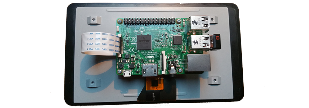
Step 5 : Install Processing on a raspberry pi 3 and touchscreen LCD
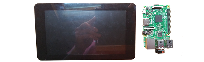
# Material
Raspberry pi 3 with his 7" touchscreen
# Install Raspian with NOOBS
NOOBS is an easy operating system installer which contains Raspbian. It also provides a selection of alternative operating systems which are then downloaded from the internet and installed.
# Install Processing for raspberry
If you want to jump right in, you can download and install Processing from the terminal with this command:
curl https://processing.org/download/install-arm.sh | sudo sh
# Installing processing for raspbian
# Connecting a raspberry pi 3/processing/touchscreen 7" with arduino board
video tutorial
Step 6 : Capturing data with sensors
# Material
# Connect arduino and raspberry pi with processing
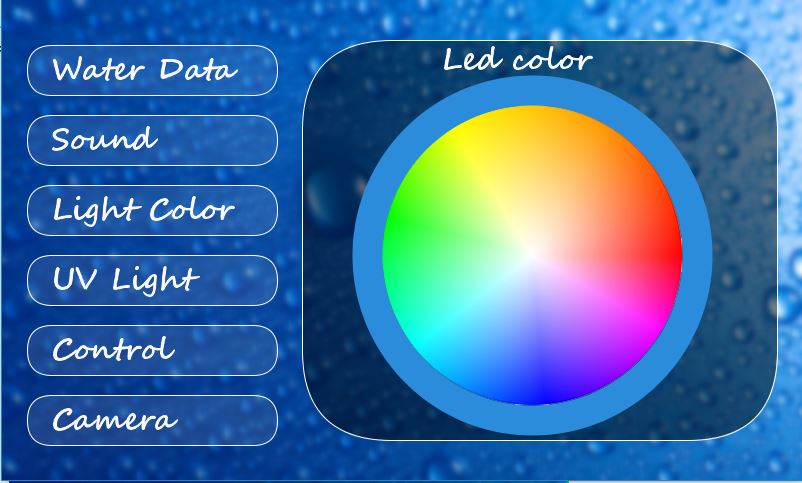
Step 7 : Make the interface touchscreen for my final project
This page is a progress report on my final fabacademy project. I will document in chronological order the questions and problems encountered in order to trace a route of answers and choices that have oriented the production of a first prototype.
Why this project ?
Step 1 : Control interface
Install Processing on a raspberry pi 3 and touchscreen LCD
Le logiciel processing sera utilisé pour concevoir l'interface numerique. Le language utilisé est le Java. Grace a cette interface nous allons pouvoir interagir plus facilement avec les utilisateurs en tant que input/output device.
# Material
Raspberry pi 3 with his 7" touchscreen est utilisé en output et en input pour interagir avec l'utilisateur, il permetra de visualiser les données captée par internet ou directement par une liaison arduino.
# Install Raspian with NOOBS
NOOBS is an easy operating system installer which contains Raspbian. It also provides a selection of alternative operating systems which are then downloaded from the internet and installed.
# Install Processing for raspberry
If you want to jump right in, you can download and install Processing from the terminal with this command:
curl https://processing.org/download/install-arm.sh | sudo sh
# Installing processing for raspbian
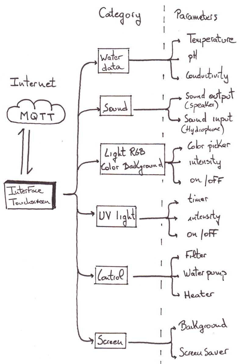
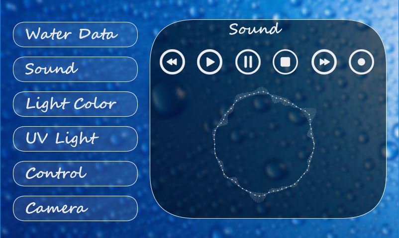
# Diagram of the interface output
Ce diagramme montre les menus, fonctionalités et parametres, avec lesquelles l'utilisateur pourra interagir.
Ces informations seront échangées avec les capteurs qui vont recevoir et emmetrer ces information grace a un module ESP.
# Interface navigation
Voici l'interface de navigation en java grace au logiciel processing installé sur le Raspbian du Raspberry.
# Connecting a raspberry pi 3/processing/touchscreen 7" with arduino board and mesure temperature
Code Processing
Step 2 : Aquarium support
# Version 1
Pendant la fabacademy j'ai profité de l'assignment sur le fraisage pour fabriquer un support d'aquarium. Une fois le support d'aquarium assemblé de nombreuse erreurs me sont apparues,
par rapport a la taille mais aussi a la forme en elle meme. Cependant cela m'a aussi donné l'idée d'embarquer de l'electronique a l'interieur. Faire ainsi un support qui integre l'alimentation, mais aussi l'electronique.
Puis pour rigoler et rendre l'objet plus interactif, j'ai decidé d'y ajouter un écran tactile qui permette a l'utilisateur d'interagir avec l'aquarium, de visualiser les données dans le temps, controler la lumiere UV,
les couleurs, activer la pompe, chauffer l'eau ou encore consulter le pH et la conductivité de l'eau. L'ideal pour cultiver des coraux et en faire un sympatique lieu d'observation de leurs magnifiques formes.
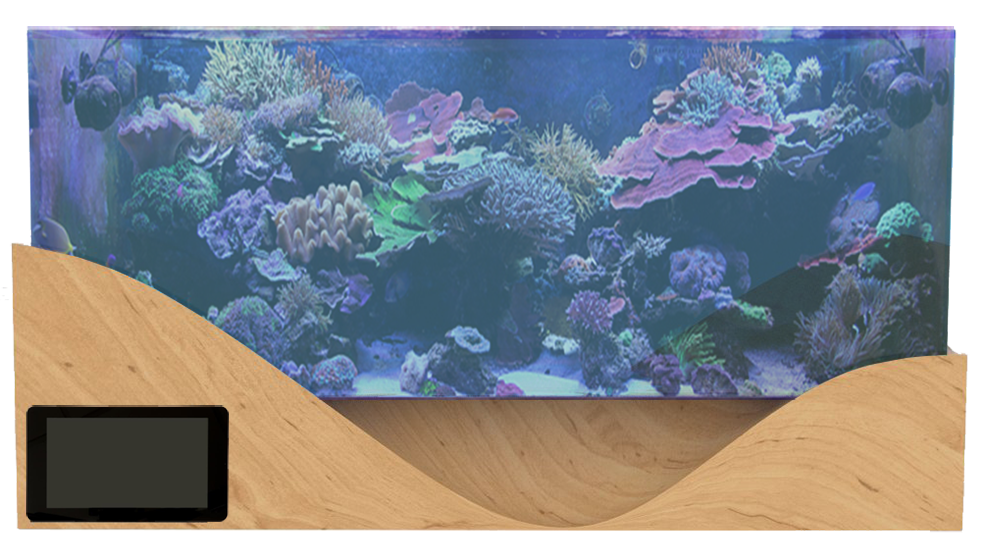
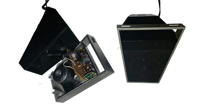
# Version 2
Avant la realisation de la version 2 de ce support d'aquarium, j'ai eu l'envie d'y ajouter une fonction sympatique.
J'ai découvert l'existence de microphones Vesper MEM cms (2 Euros) qui ont la capacité d'etre étanche et de capter des sons sous l'eau. Alors j'ai immédiatement pensé qu'en plus d'offrir une vue sur des coraux,
il y a la possibilité de creer une ambiance sonore sous marine, grace a un hydrophone et de simples petits haut parleur. J'ai donc modelisé ce support d'aquarium avec l'emplacement de deux haut parleurs afin d'amplifier les sons aquatiques qui se trouvent dans l'aquarium.
# Modelisation
# Cutting files
# Cutted part assembled
# Sanding the support
# Resulting Shape after sanding
# Final result
# Files
Step 3 : 3D printed Artificial Reef
# Why artificial reef ?
Explicationrecif artificiel
# Reef 1
# Reef 2 3d printed
Step 4 : Temperature sensor, RGB Led and UV Led
# temperature
Material
Afin de capter la temperature de l'aquarium, j'ai choisi un capteur de temperature étanche compatible avec arduino: DS18B20
Prototyping
Pour les premier test j'ai utilisé le meme capteur dans sa version non étanche, mais leur fonctionnement sont simmilaires et ne devraient pas poser probleme.
J'ai donc utiliser un breadboard pour tester le cablage.
Temperature visualization with arduino and Processing
Afin de visualiser la temperature, j'ai programmer une programmation en serie entre la satshakit et processing sur raspberry pi 3. Je dois maintenant integrer la visualisation de cette courbe a l'interface tactile.
Code Arduino
Afin de reconnaitrele capteur de temperature DS18B20, il est necessaire d'installer une librairie arduino appelée : One wire. La communication serie est a 9600 Bauds.
Et on recupere la valeur du cateur sur le moniteur serie. Pour installer cette librarie, il suffit de cliquer dans le menu croquisde l'IDE arduino > inclure une bibliotheque > gerer les bibliothèques. En suite une fenetre s'ouvre avec une barre de recherche. Dans cette barre de recherche tapez one wire et rechercher. Il existes plusieurs librairies disponibles. Certaines permettent meme de connecter jusq'a 32 capteur de temperature en simultané. En ce qui nous concerne nous cliquons sur la plus simple d'ente elle : OneWire by Jim Studt, Tom Pollard etc..
J'ai decider d'ajouter une fonctionalité sympathique a cet aquarium : le son. Afin d'immerger le spectateur dans une ambiance sonore bulbeuse et attirer vers le spectacle des recifs.
Pour cela j'ai choisi un microphone MEM cms waterproof afin d'enregistrer les sons de l'aquarium. puis j'ai trouvé une vaire paire de haut parleur pour pc avec sa basse.
Je vais donc recycler ce qui son et l'integrer intelligement dans le support de l'aquarium.
# how use the sound in processing ?
import minim library
Minim is an audio library that uses the JavaSound API, a bit of Tritonus, and Javazoom’s MP3SPI to provide an easy to use audio library for people developing in the Processing environment. The philosophy behind the API is to make integrating audio into your sketches as simple as possible while still providing a reasonable amount of flexibility for more advanced users. There are no callbacks and you do not ever need to directly manipulate sample arrays, all of the dirty work is handled for you.
How to play sound by loading a mp3 file in processing ?
Voici un sketch recupéré sur le site de processing. il s'agit un sketch tres simple qui permet de lire un fichier audio sur votre ordinateur a partir de processing.
je vais donc adapter ce sketch et l'ameliorer pour disposer d'un veritable lecteur audio sur l'interface de mon aquarium.
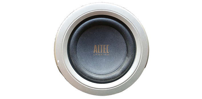
# Recycle old Speakers
# Sound visualisation
# Hydrophone MEM cms
Step 6 : Heater, pH and conductivity
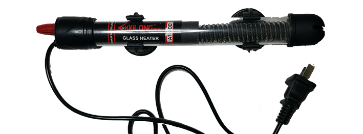
# Heater
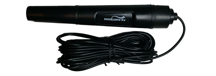
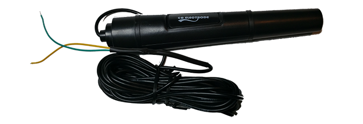
# pH sensor
pH sensor arduino board
I discovered that there existed arduino modules to connect the ph probe to the arduino.
Then searching on the site of the fabacademy. I discovered that during the Fababademy 2015 of Leon Fablab, a student had worked on a diy arduino module of pH calculation.
I thank him very much and I think I will reuse his work as part of my project to avoid buying an industrial pH module.
# Conductivity sensor
RESULT
FINAL PROJECT
This page is a progress report on my final fabacademy project. I will document in chronological order the questions and problems encountered in order to trace a route of answers and choices that have oriented the production of a first prototype.
SLIDE PRESENTATION
VIDEO PRESENTATION
APPLICATION PRESENTATION
Invention, Intellectual Property and Business Models
Creative Commons is a non-profit organization that aims to facilitate the dissemination and sharing of works while accompanying new creative practices in the digital age.
Creative Commons offers standard contracts or licenses for the supply of works online. Inspired by free licenses, open sources and free access, these licenses facilitate the use of works (texts, photos, music, websites, etc.).
These licenses are for authors wishing to:
share and facilitate the use of their creation by others
allow free reproduction and distribution (under certain conditions)
more rights for users by completing the copyright that applies by default
to evolve a work and enrich the common heritage (common or common goods)
save transaction costs
to legalize the peer-to-peer of their works.
Attribution
All Creative Commons licenses require those who use your works to credit you the way you request it, without suggesting that you approve their use or give them your endorsement or support.
No commercial use
You authorize others to reproduce, distribute and (unless you choose 'No Modification') to modify your work, for any use other than commercial, unless they obtain your prior authorization.
SHARING IN THE SAME CONDITIONS
You authorize others to reproduce, distribute and modify your work, provided that they publish any adaptation of your work under the same conditions as your work. Anyone wishing to publish an adaptation under other conditions must obtain your prior permission.
NO MODIFICATION
You authorize the reproduction and diffusion only of the original of your work. If someone wants to change it, they must get your permission.
1 / ATTRIBUTION LICENCE
Le titulaire des droits autorise toute exploitation de l’œuvre, y compris à des fins commerciales, ainsi que la création d’œuvres dérivées, dont la distribution est également autorisé sans restriction, à condition de l’attribuer à son l’auteur en citant son nom. Cette licence est recommandée pour la diffusion et l’utilisation maximale des œuvres.
ATTRIBUTION + NO MODIFICATION LICENCE
The rights holder authorizes any use of the original work (including for commercial purposes), but does not authorize the creation of derivative works.
2/ ATTRIBUTION + NO MODIFICATION + NO COMMERCIAL USE LICENCE
The rights holder authorizes the use of the original work for non-commercial purposes, but does not authorize the creation of derivative works.
3/ ATTRIBUTION + NO COMMERCIAL USE LICENCE
the owner of the rights authorizes the exploitation of the work, as well as the creation of derivative works, provided that it is not a commercial use (the commercial uses remaining subject to its authorization).
4/ ATTRIBUTION + NO COMMERCIAL USE + SHARING IN THE SAME CONDITION LICENCE
The rights holder authorizes the exploitation of the original work for non-commercial purposes, as well as the creation of derivative works, provided that they are distributed under a license identical to that governing the original work.
5/ ATTRIBUTION + SHARING IN THE SAME CONDITION LICENCE
The rights holder authorizes any use of the original work (including for commercial purposes) as well as the creation of derivative works, provided they are distributed under a license identical to that governing the original work. This license is often compared to copyleft licenses for free software. This is the license used by Wikipedia
FINAL PROJECT
For my final project, my choice is on the choice of a CC-BY-NC-SA license.
Because I wish to leave the opportunity to everyone to open to the world of the aquarist for non-commercial purposes. That each individual having access to a fablab can build his connected aquarium and improve it. Having and maintaining marine life on a daily basis requires us to reflect on the degradation of the oceans and the ecological problems facing all of us. I hope it will allow people who encounter this strange object to realize the beat of a living ecosystem.


 I clean my pcb board with isopropyl alcohol
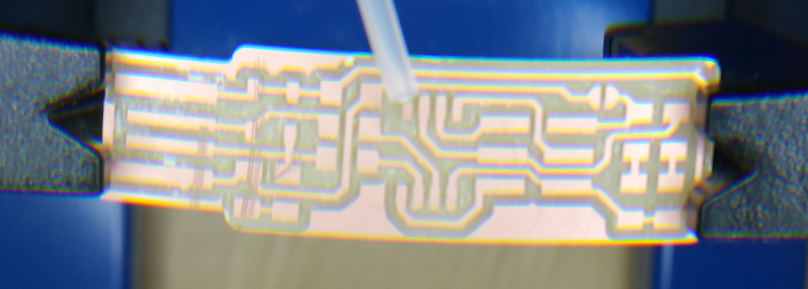
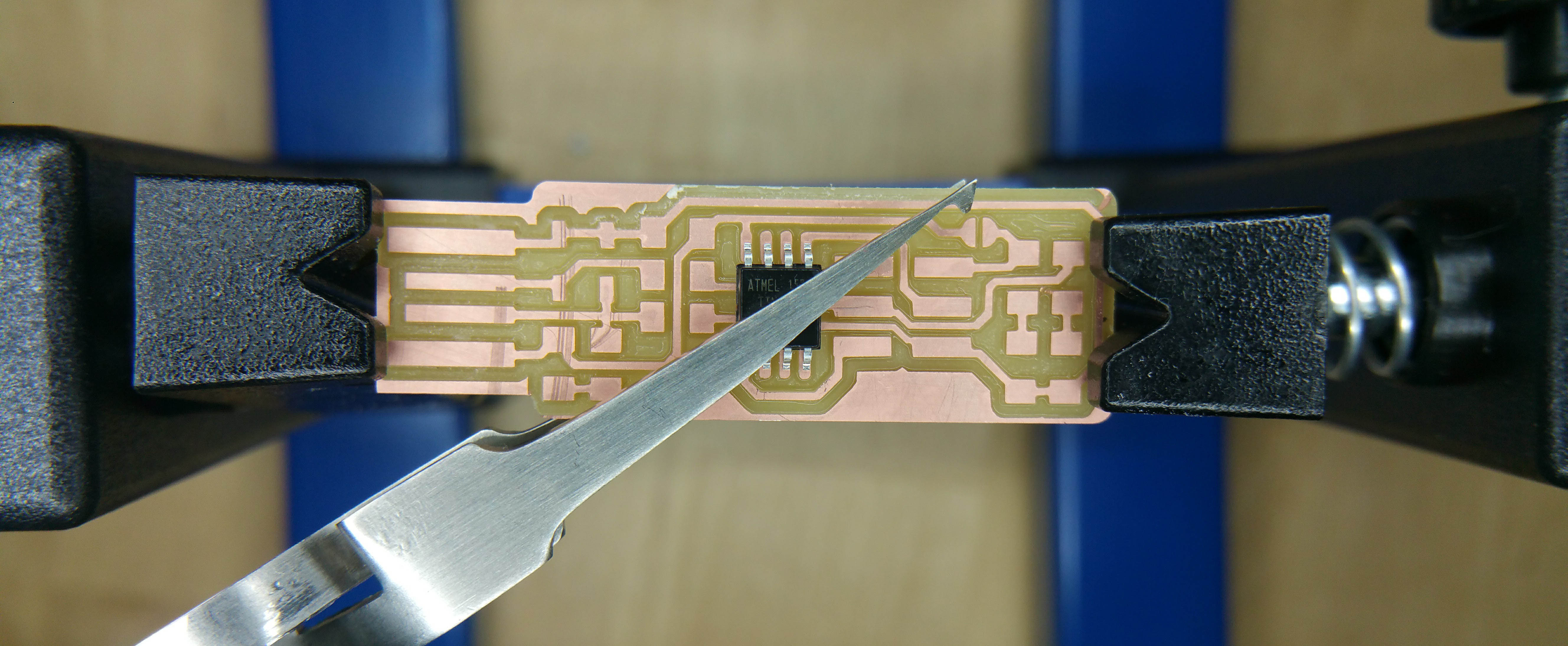
 with the soldering iron i heated every pin of the AtTiny 45 to weld them in the same time.
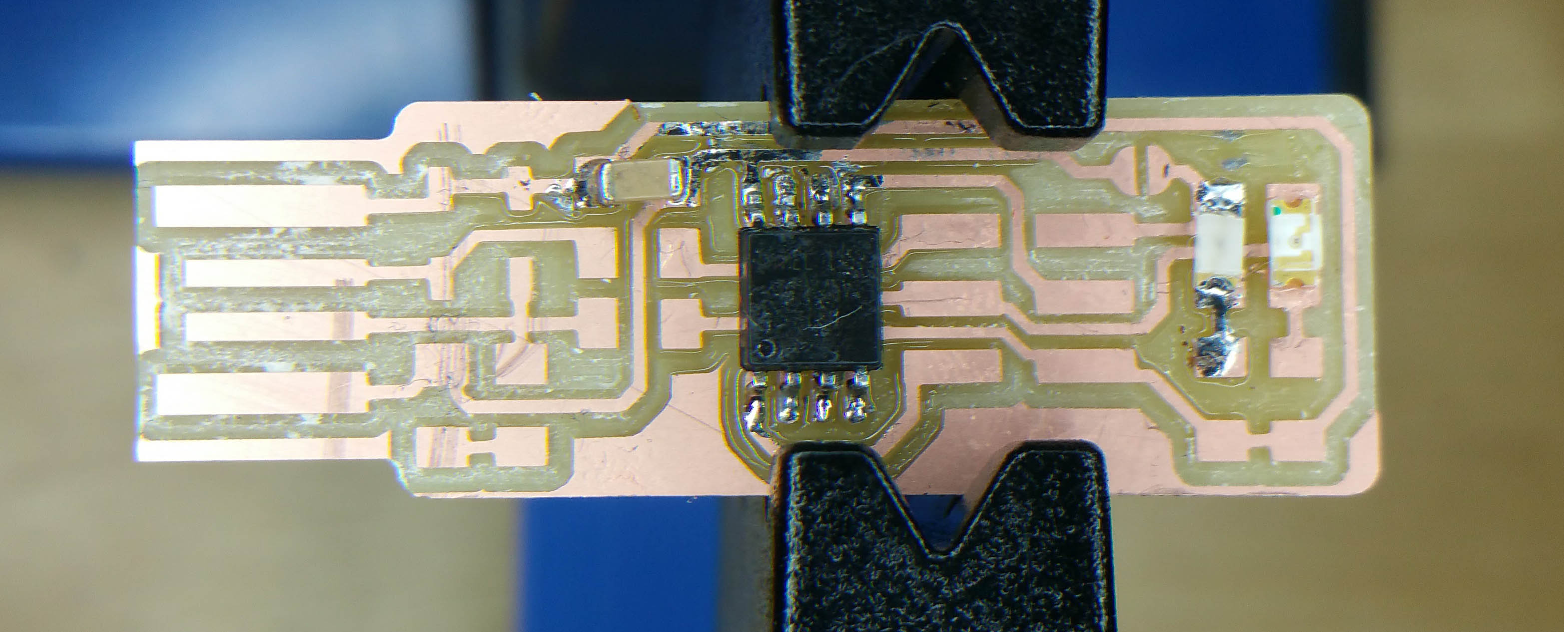 I do the same thing for the red an green diodes.
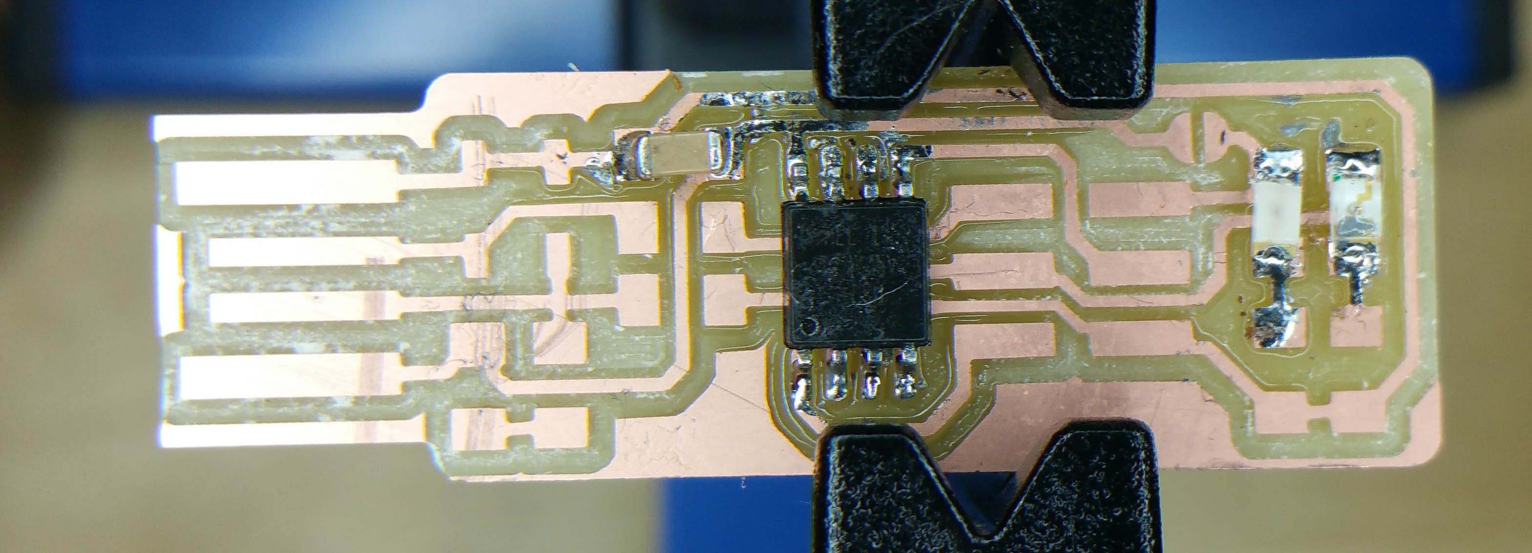 Then with the resistances.
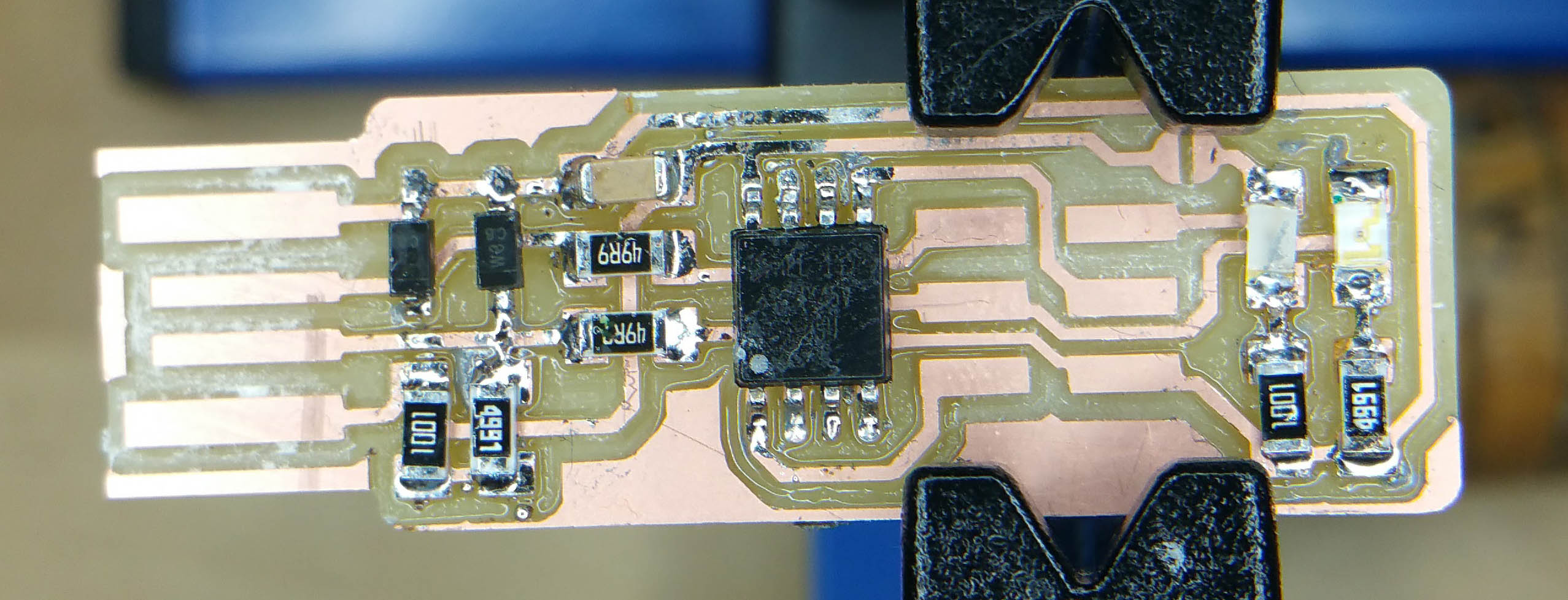 This is the final product.
 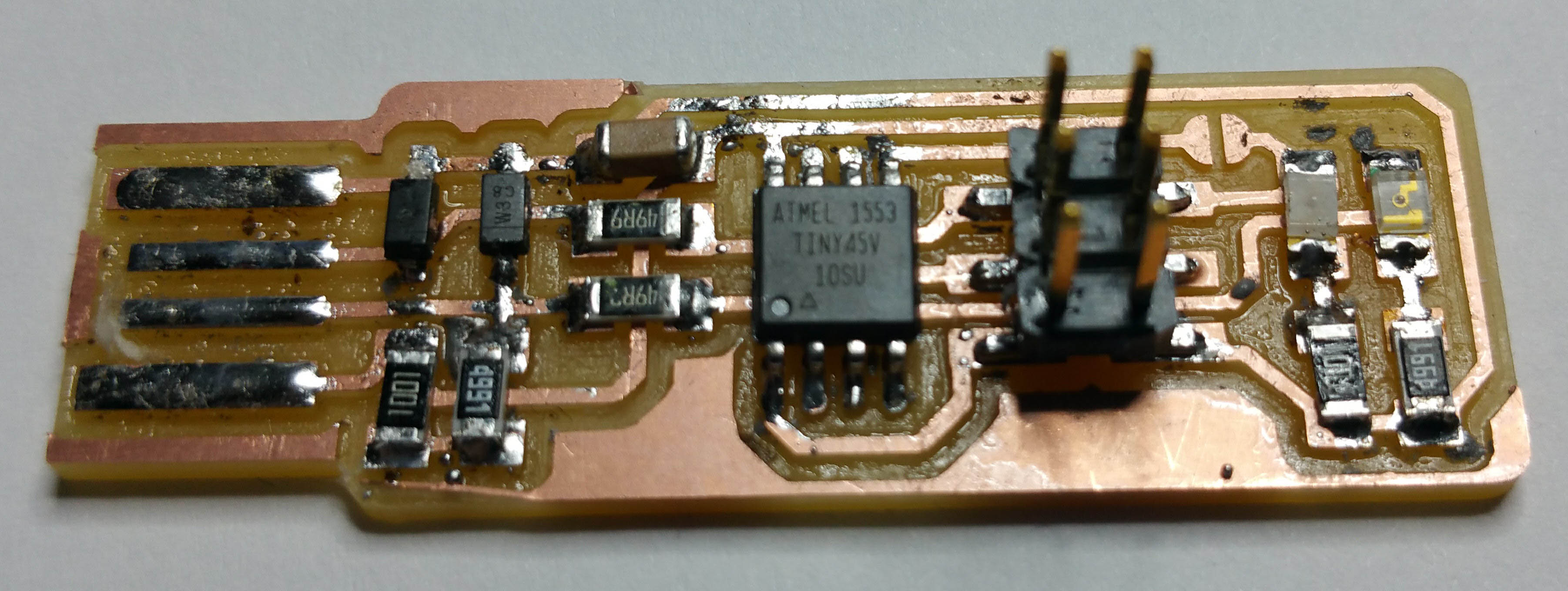 This is the final product with the connector.
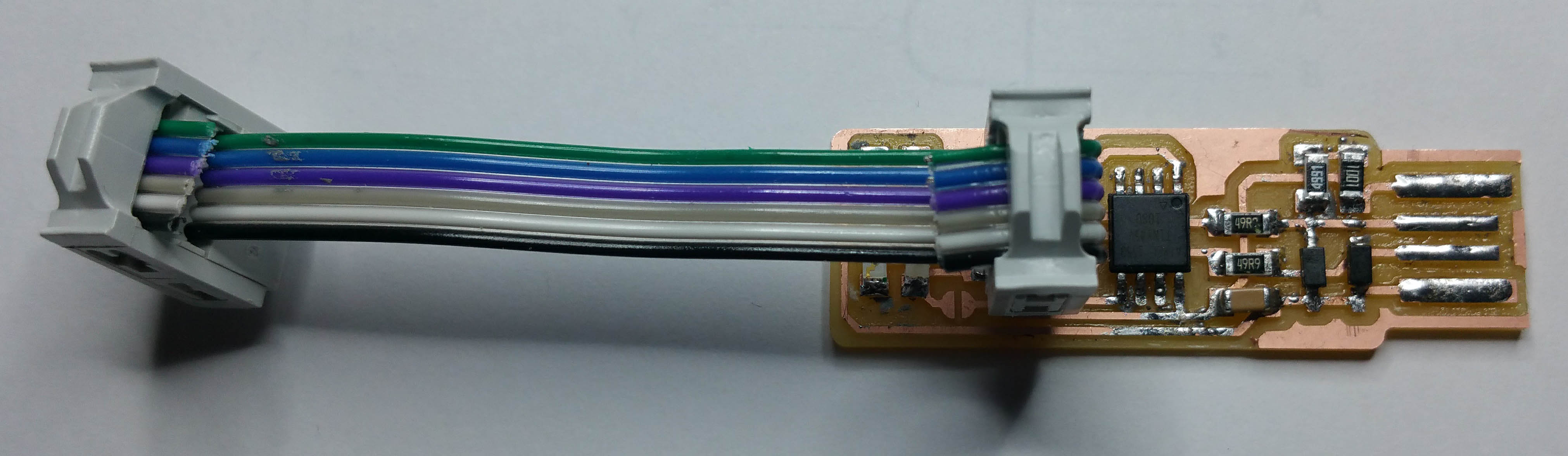


.png)
else.png)
elseif.png)


 arduino-TEMPERATURE


