Abstract
This week was about the big CNC and how to output a big piece.
Some of the question raised were:
- How to translate a 3D design into 2D cuttings?
- How the mill dimensions impact the design? / What milling sequence to choose?
- How to optimize board space?
- How to design joinery?
- What are the limitations of CNC?
- What inter-sofware workflow to pick? For which purpose?
- How to simulate the cutting?
The main obstacle was the designing part. Switching between 2D and 3D requires some practice.
The basic rules being:
I mainly used 1 workflow:
Fusion 360 > Rhino (layers) > VcarvePro
My biggest achievement: My first hand made furniture in my living room (also a passer-by compliment "That's pretty" as I carried it on the street)
My biggest struggle: Having a clean design
Chronology
| Thursday | Friday | Monday | Tuesday |
|---|---|---|---|
| Introduction to CNC | Design Fusion | File Cleaning | CNC |
| First design ideas | Design Rhino | Assembly | |
Setup
| Softwares | Fonction |
|---|---|
| VCarve Pro | Cutting parameters and ncode generator |
| Fusion 360 | CAM simulation |
Skills acquired
Asssesment validation
Preparatory work
Small size project/test
I went to the Second maker square at Carreau du temple and followed a tutorial on how to make frames from DM Makers. My first aim for this week was to reproduce the same worklow. The constraints to take into account were: -
a wide enough frame -
reinforcements -
chamfered upper faces so that the canvas would be strechted without being constrained by the wood. DM Maker milled plain wood with Techshop CNC based on CAM models in Fusion360. As for WoMa they are used to VCarve with layered DXF as input and the material I will be using is plywood. The first task was to translate one way of doing into the other. Also I wanted this frame to be a gift so I had some constraints from the recipient. He wanted a multi-frame or a panoramic one. I picked the firt option as it could involve joinery. I also wanted some criteria to be respected:
- Small frames that could be separated when painted and reunited afterwards
- Frames that could be used as a grip while painting
- Mostly right angles so that the streching of the canvas would be easier I used this project as a CNC test. The reinforcement part had to be thinner than the frame so it would involve pockets. The chamfer of the upper face would involve a V-shape end-mill. I also wanted to test bending wood, so I designed a part to overline the two frames once fitted together. This part will have two kinks, I imagined those kinks made possible by parametric karf.

extruded canvas
Drawing with Fusion
1. Sketch the frame (width 3.5cm)
2. Sketch the reinforcement part (sketched separetly because they will be esxtruded at different heights)
3. Extrude both (frame: 18 mm and reinforcement: 12.2 mm)
4. Combine the 2 bodies
5. Chamfer with distance and angles the inner *face* (distance 10 mm angle 30°)
6. Export sketches as DXF
7. Open Rhinoceros
8. Create collection of layers (CUT ON, CUT IN, CUT OUT, POCKET)
9. Assign layers to curves
10. Create polylines for the lacking geometries
11. Add circle at CUT IN angles so they don't come out rounded
12. Trim/join circle and polyline
13. Export as DXF to VCarve
Source file to load here
Vshape anticipation
In order to chamfer Vshape endmill had to be used. The slope is function of the mill, I picked a 120° one with a 7 cm diameter. That's why at first I put a width of 3.5cm for the frame, so it would be chamfered all along. But I forgot to measure the height of the conic part which was 2.3 cm (thicker than my material).
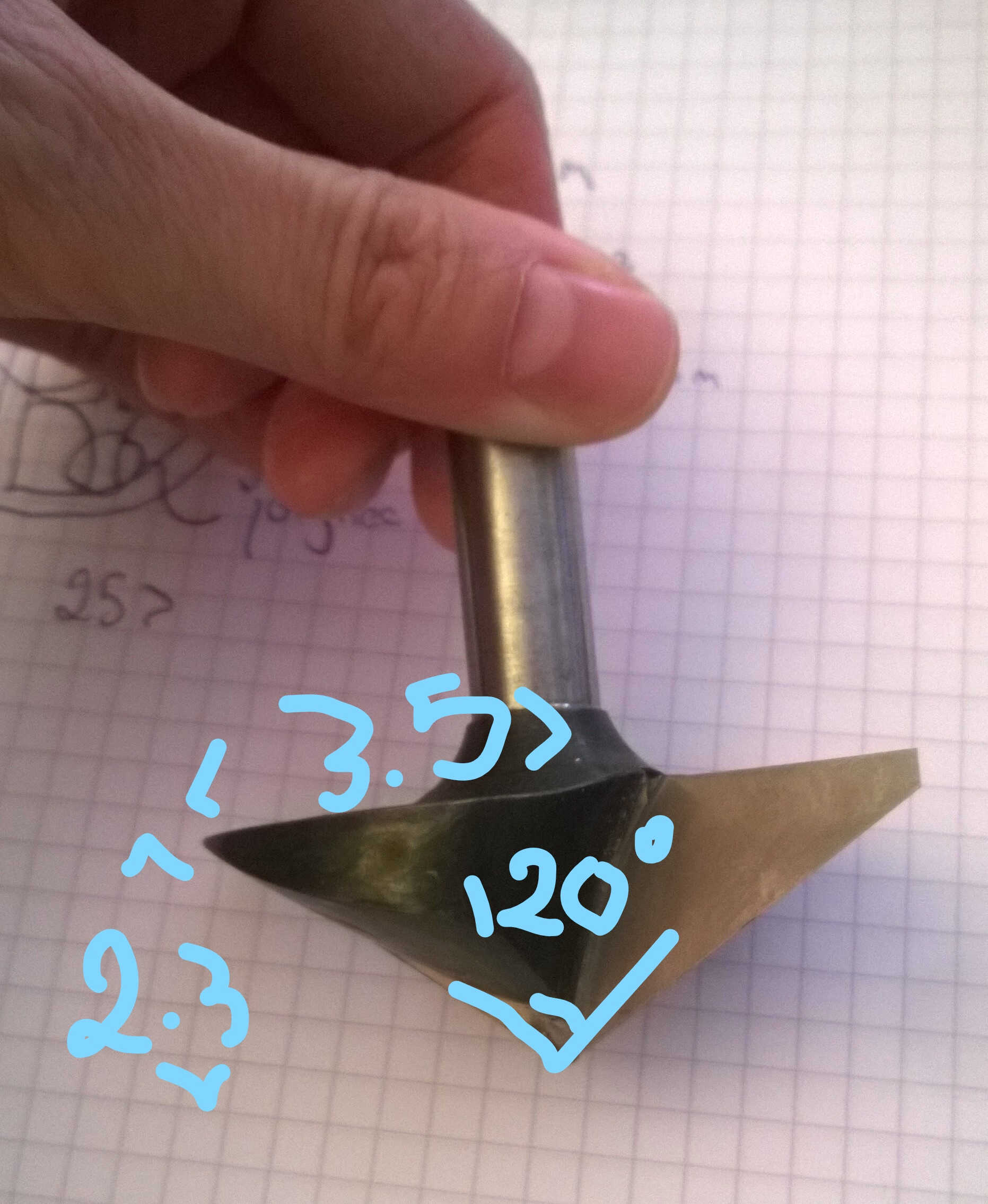
Vshape end mill 120°
Not could I chamfer all the way down only up to the reinforcement. The angle of the resulting slope being 30°, I arbitrarily chose a chamfer distance of 10 mm.
As tan(30) x 10 = 5.77, the chamfer height would then be 5.77 mm and the reinforcement 12.23 cm (18-5.77).
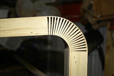
Kerf
I did a lot of research on kerfing as I intended to test bending wood. There is such an example on a shelf at WoMa. The bending of the example comes from alternate incisions on both side and from a spinal depression.
Picture! I wanted to test something slightly easier: cuts on the whole width but not going through the material only throught 3/4 of it.
expectation
The formula for such a pattern are those ones:
Length = radius x pi
Inner radius = Outer radius - 3/4 material thickness
Outside length(Lo) - inner length(Li) = the material length to be removed (R)
R/end-mill width = kerf number (Kn)
Lo/Kn = Kerf spacing (Ks)
I considered building a small table based on kerfing
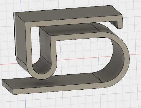
3D table
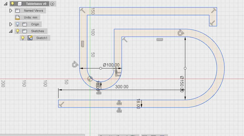
table dimensions
Main piece conception
I had to reorient my project idea as Thomas pointed out that there was no joinery involved. The frame was only meant to be a test/practice, to better understand the end mill characteristics. We finally had less time with the CNC than expected. So the time devoted to test was reduced to zero. I found my inspiration on Pinterest . I liked the design, the press and fit joinery and its biomimicry inspiration, also it was only made of 2 different pieces.
Two pieces compound
Fusion 360
I used my rests of trigonometry to fullfill this project. To calculate the slot width I had to know the material width and the angle formed between the pieces.
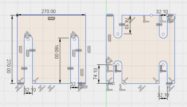
- I decided to do 27cmx27cm square pieces because my first idea was to make a shoe rack out of it. My shoe size being 41, my shoes are 27 cm long. Also 27 is easely divided in 3.
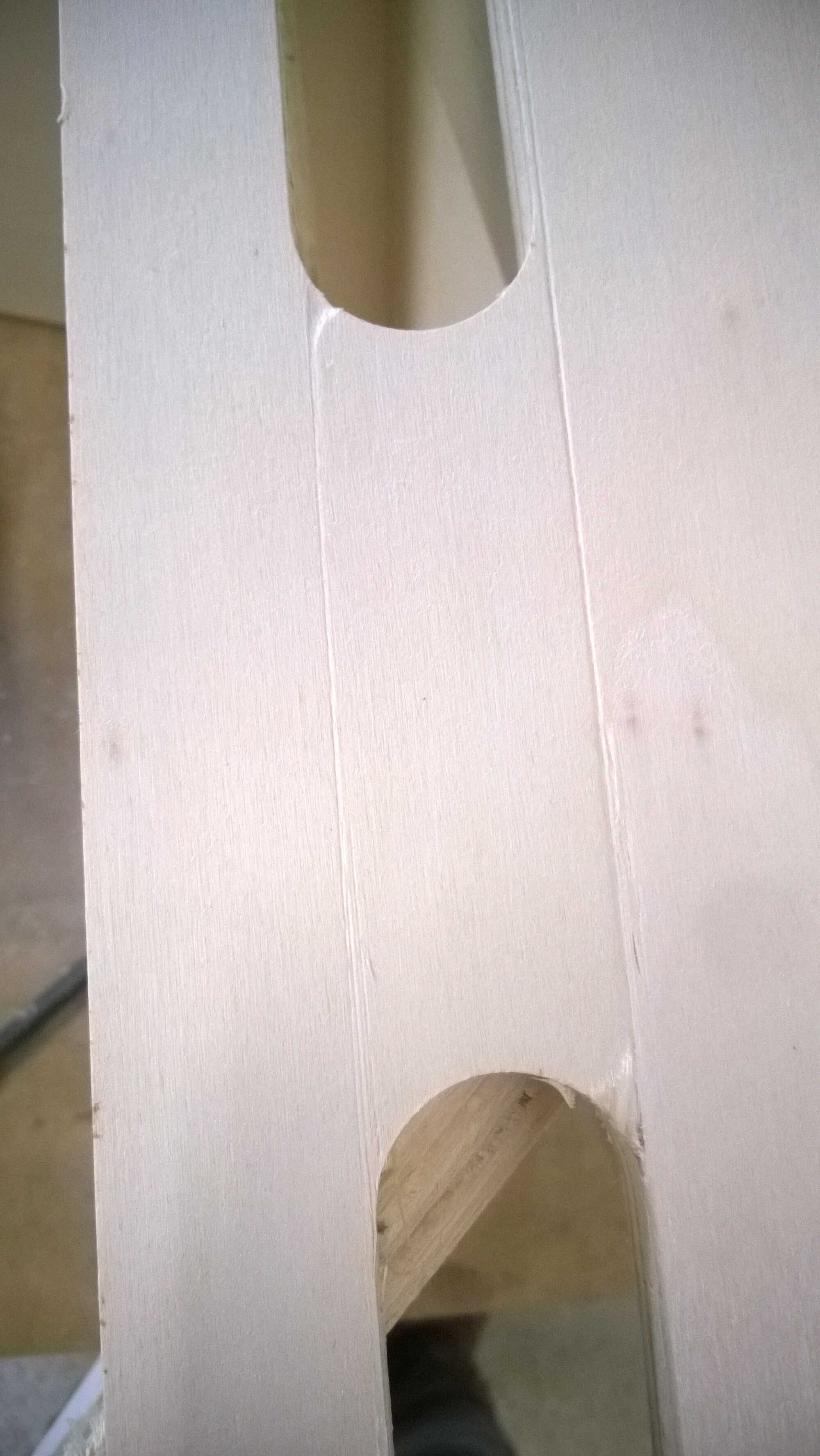
- The slot length was either 1/3 or 2/3 of the square length with a round end. I tought this would provide some liberty. After completion I think a sharp end would have helped the assembly process.
- The plank was measured with a caliper and was 1.84 cm wide
- The slot width was the tricky part. My calculation was w = tan(30°)x1.85 + 1.85/cos(30°) = 3.21cm I made a sketch on Fusion 360 in order to check, with the sketch dimension I obtain 2.184 + 1.1 = 3.284 cm
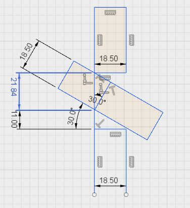
Slot width
I couldn't figure out the reason of discrepancy between the 2 methods.
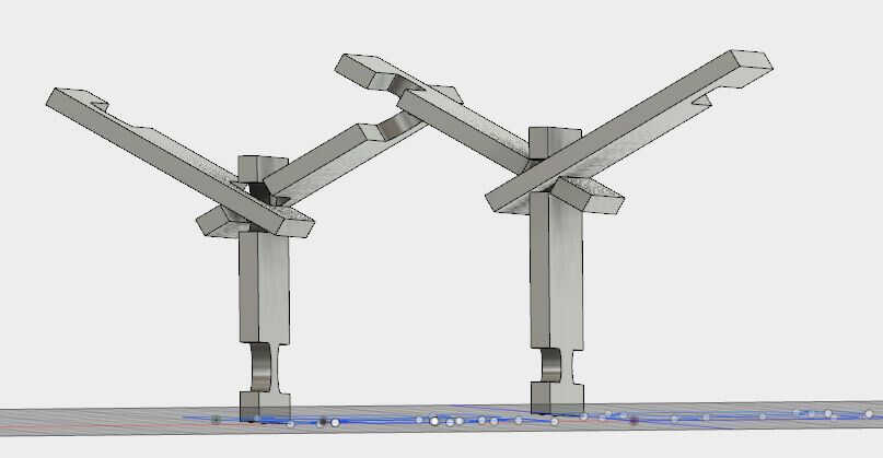
Once the dimensions computed I parametrically designed my pieces in Fusion.
Once done I extruded then (1.85cm thick) and moved them in 3D to mimick the final geometry.
This process validates the dimensions.
My first try showed me an error in the slot width, the second an error in the slot length.
I corrected them until the visualization validated my dimensions.
slot width issue
slot length issue
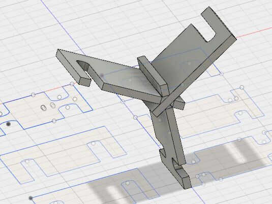
Fusion assembly validated
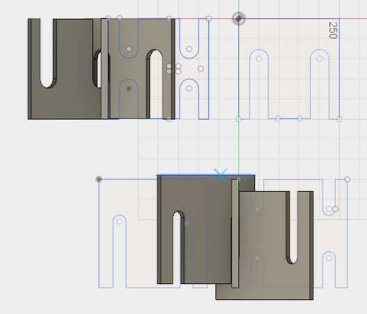
The same checking process was done later in Rhino.
Rhino
Once the design done, I had to export in dxf format to Rhino to close the polylines (Join + Trim tools) and to add layers.
Layered dxf are read in VCarve, this enable toolpath to be computed for each layer separately.
The names should enclose all the information needed: the cutting type, the cutting depth and the endmill used.
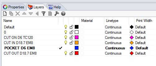
layers naming
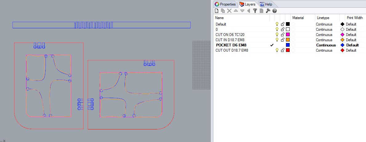
canvas Rhino layers
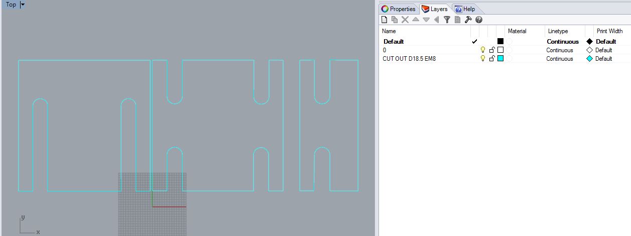
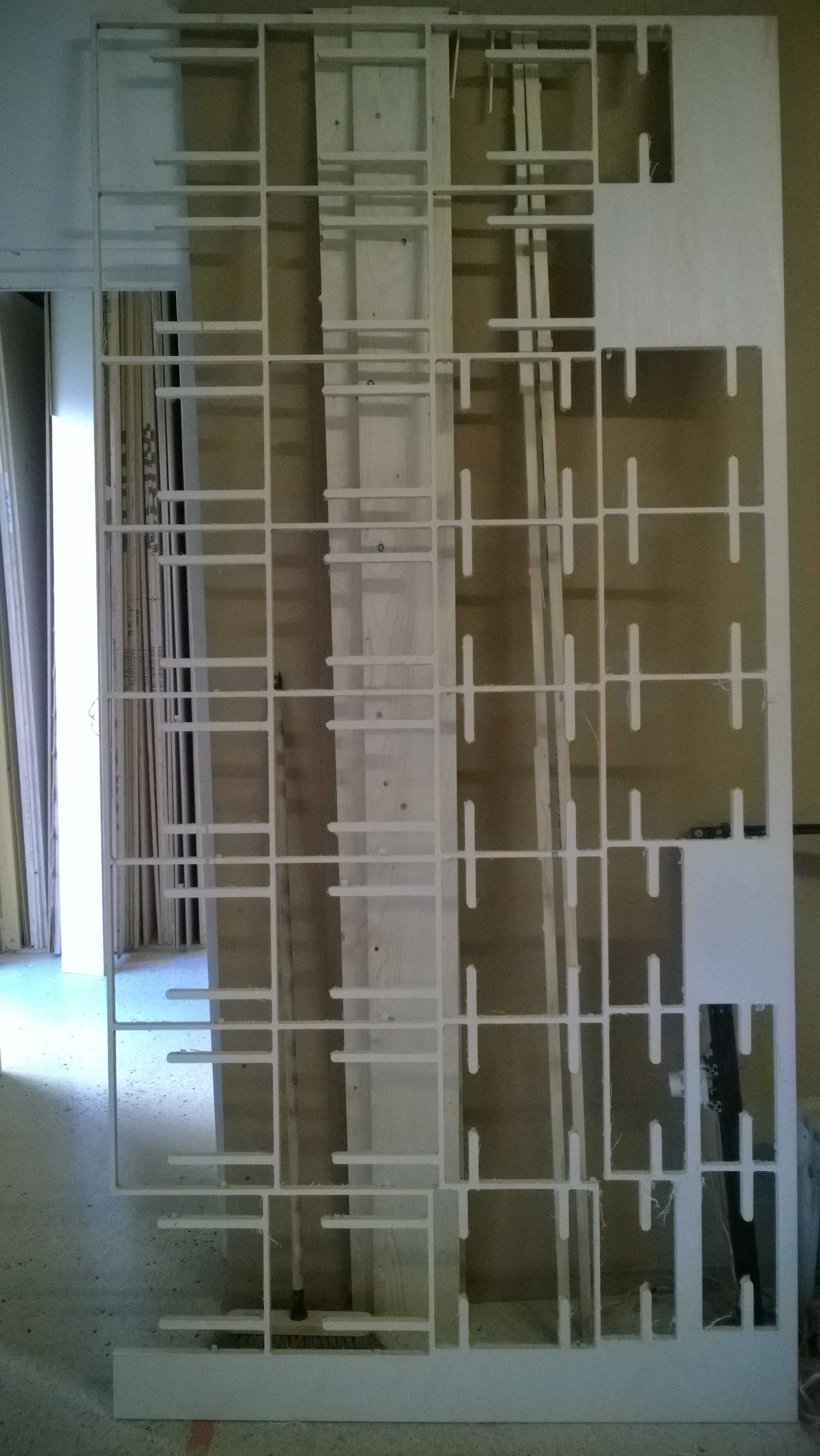
one-layered hive design
Source file of the hive furniture to load here
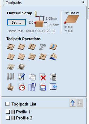
VCarve Pro
1.The DXF is imported in VCarve.
2. The board dimension are defined
3. Untick XY Datum position offset
4. Click Ok at the bottom of the Job Setup
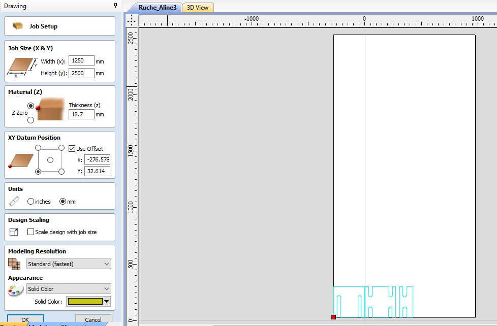
job setup
5. Some vectors are read as open. I used Edit objects: Join open vector tool to close them, taking care of changing the tolerance.
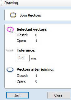
close curves
6. Toolpath definition window opening (tab on the right side)
7. Select profile toolpath
8. Set the cutting depth (material thickness + 0.2 mm )
9. Select 8 mm endmill for poplar/ create one/import one in the tool database. I imported mine from WoMa VCarve library, copied the wood 8mm endmill and changing the feed rate to 6000 mm/mn.
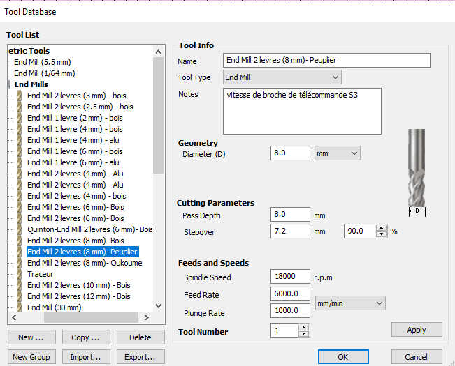
Poplar endmill
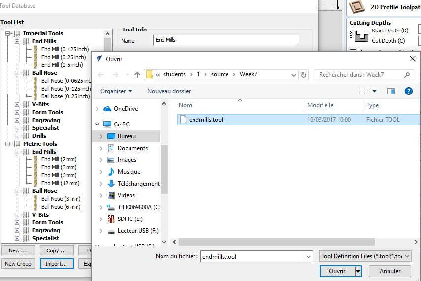
importing a tool
10. Outside + conventional machine vector
11. Add tabs > Edit tabs > Constant number set to 2> Add
12. Calculate (the toolpath are computed)
13. Preview all toolpaths in order to simulate the result
14. Estimate time
15. Select the toolpath one by one and save them as gcode on an USB key
toolpath types
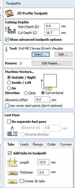
contour toolpath parameters
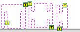
adding 2 tabs/piece
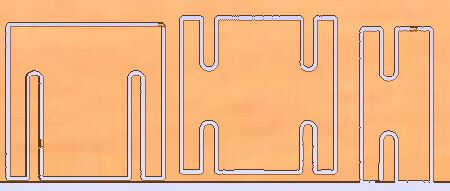
cutting simulation (notice the tabs)
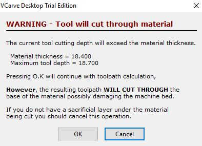
warning
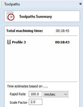
time estimate
I redid the same procedure this time with all the pieces. I made them all fit on the board by using the Nest vectors tool. This option minimizes the material wastage (this is a VCurve Pro feature). I copied my pieces in order to have 6 bases (the smallest piece, basically a vertical piece cut in half), 9 vertical pieces and 18 horizontal ones.
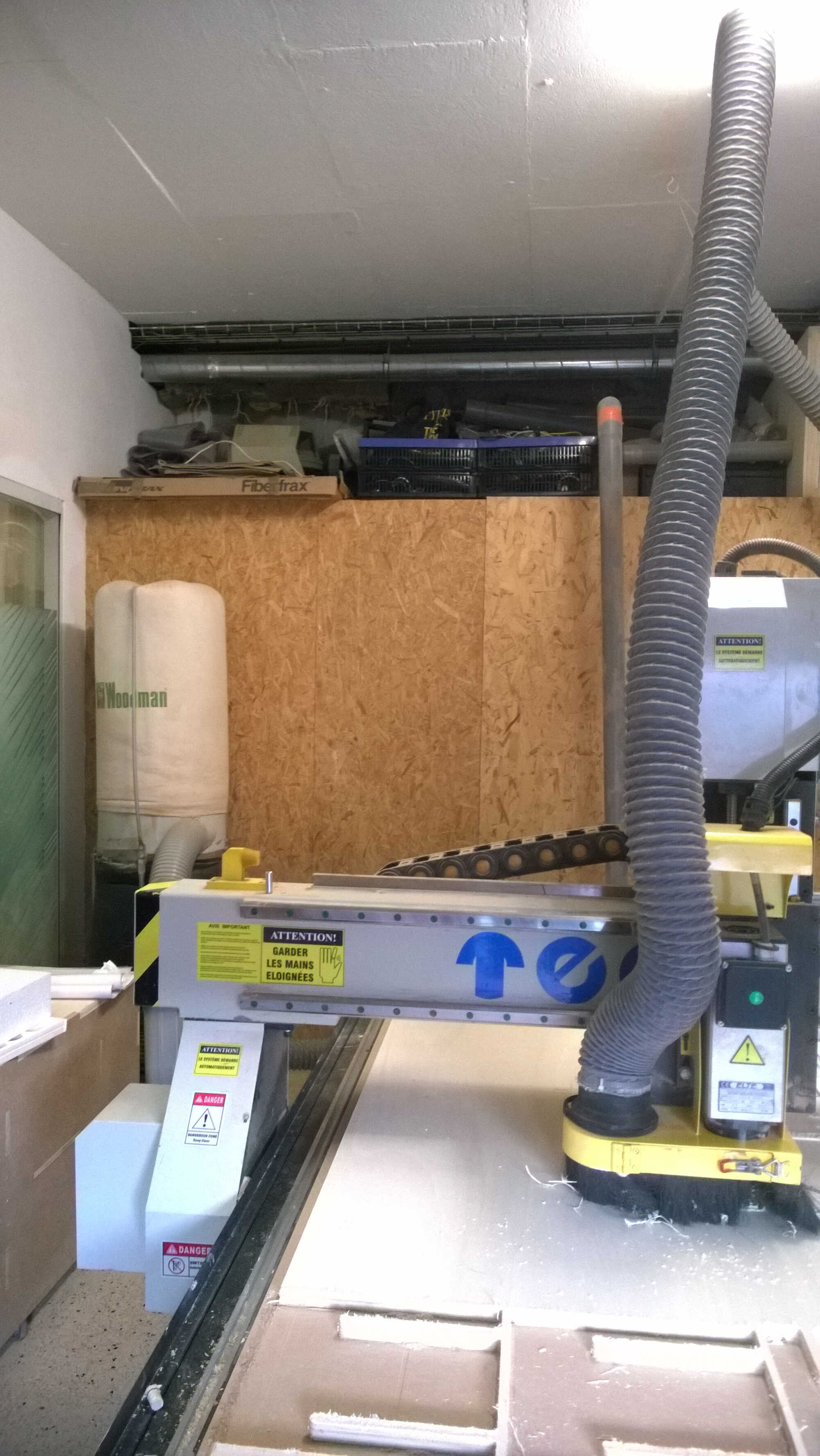
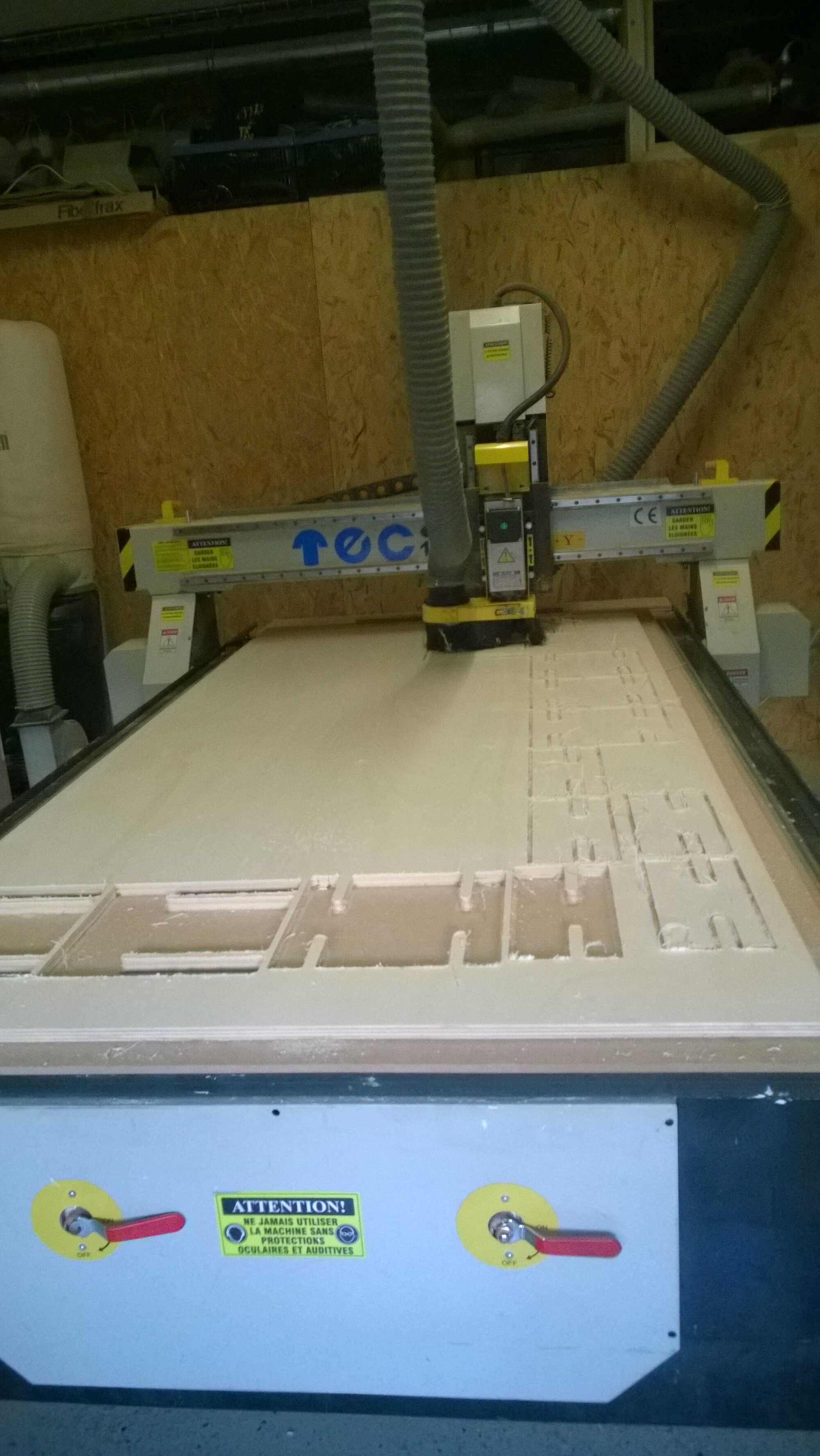
CNC setting
It is now time to approach the CNC. WoMa's CNC is a Perez Camps Tech CAM 1000 . The wood board is placed on the CNC bed. Thanks to its size and to the vaccum it doesn't need to be fixed. Then the end mill is picked: a 8mm with 2 flutes. Then it had to be screwed on the CNC with some dedicated tools. Once fixed the origin is set -in a similar way it was on the small CNC we used to mill PCB boards. The head is displaced with the controller buttons X+/X-/Y+/Y-/Z+/Z-. The controller is hold inclined so the direction reflect the board orientation (OK on the right) The XY = 0 is made at the bottom right of the machine (the corner next to the vaccum pump). It is saved by pressing on the button XY=0 of the controller.
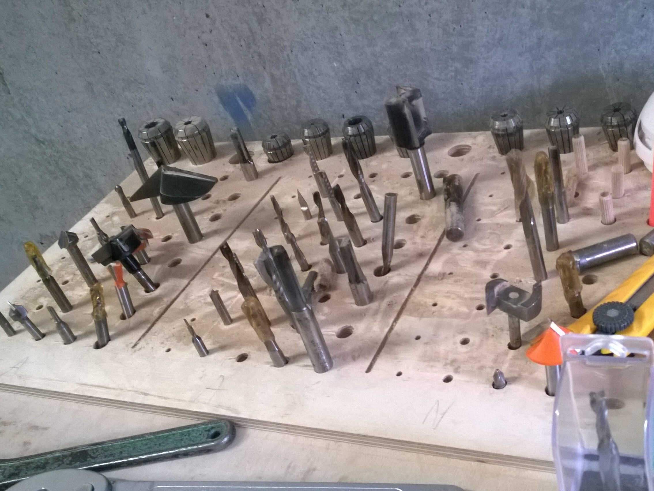
end mill choice
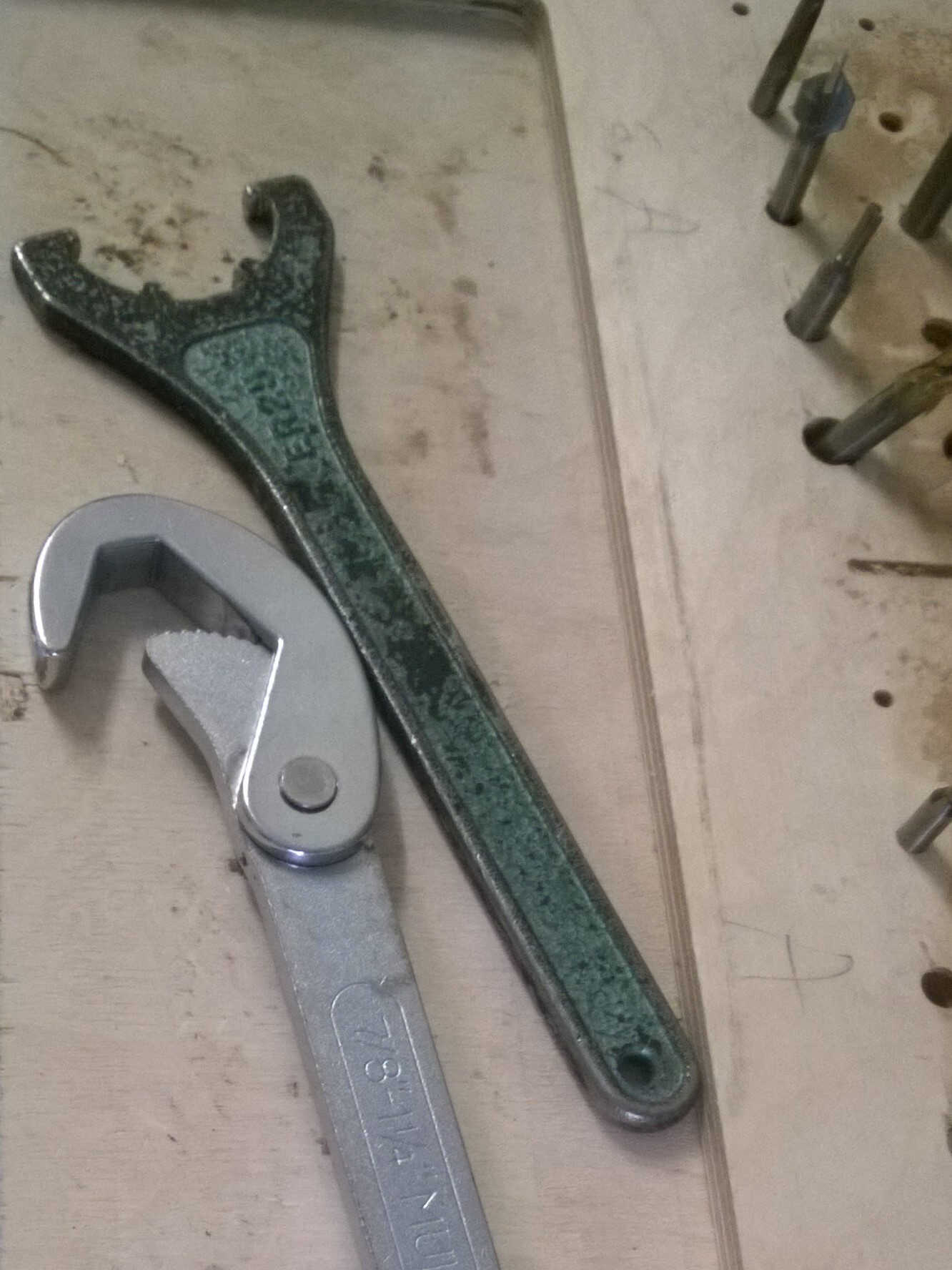
tools needed to change the end mill
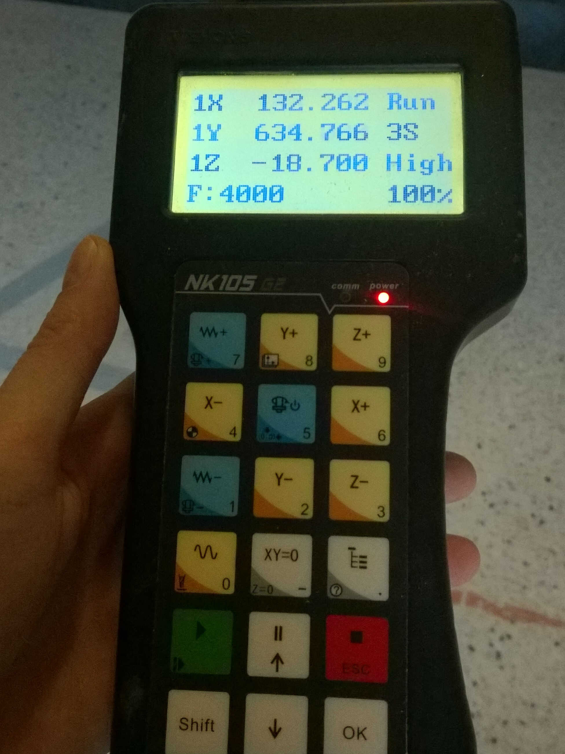
CNC controller
All set. Time to turn the vaccum pump on (green button)to do the Z.The Z is done with the help of a paper, the step of displacement is changed by pressing shift. Once the paper is blocked by the end mill the Z is saved by pressing on XY=0 and Shift simultaneously. The aspiration is turned on. The gcode on the USB key is plugged on the vaccum pump. It can be retrieved with the controller. The first tool path gcode is selected by pressing the button with the branching, below Z-. The milling is launched by pressing the play button.The controller is held in the hand during the cutting to be able to press pause if something goes wrong or catch fire. Also we want the spindle to rotate at 3S speed, so when it switches to 2S shortly after the start I pressed Shift simultaneously with.
vaccuum pump
aspiration
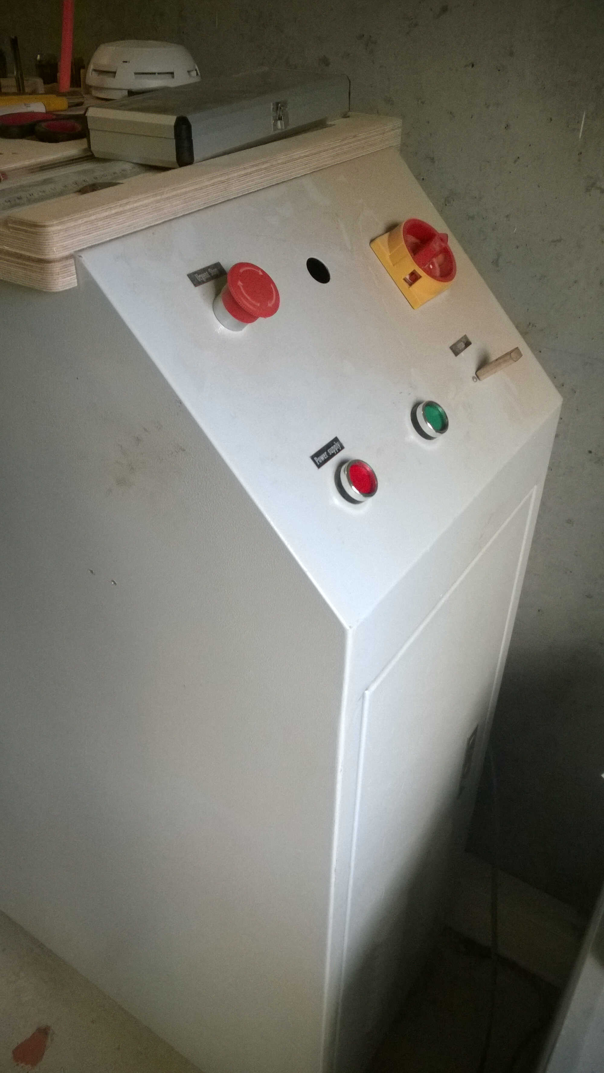
Safety first
Even if the aspiration removes most of the wood dust a mask can be a nice compliment and it protects you from the burn smell. Never get close to the machine while it is working, the line on the ground is here to remind you of this.

Mask and glass
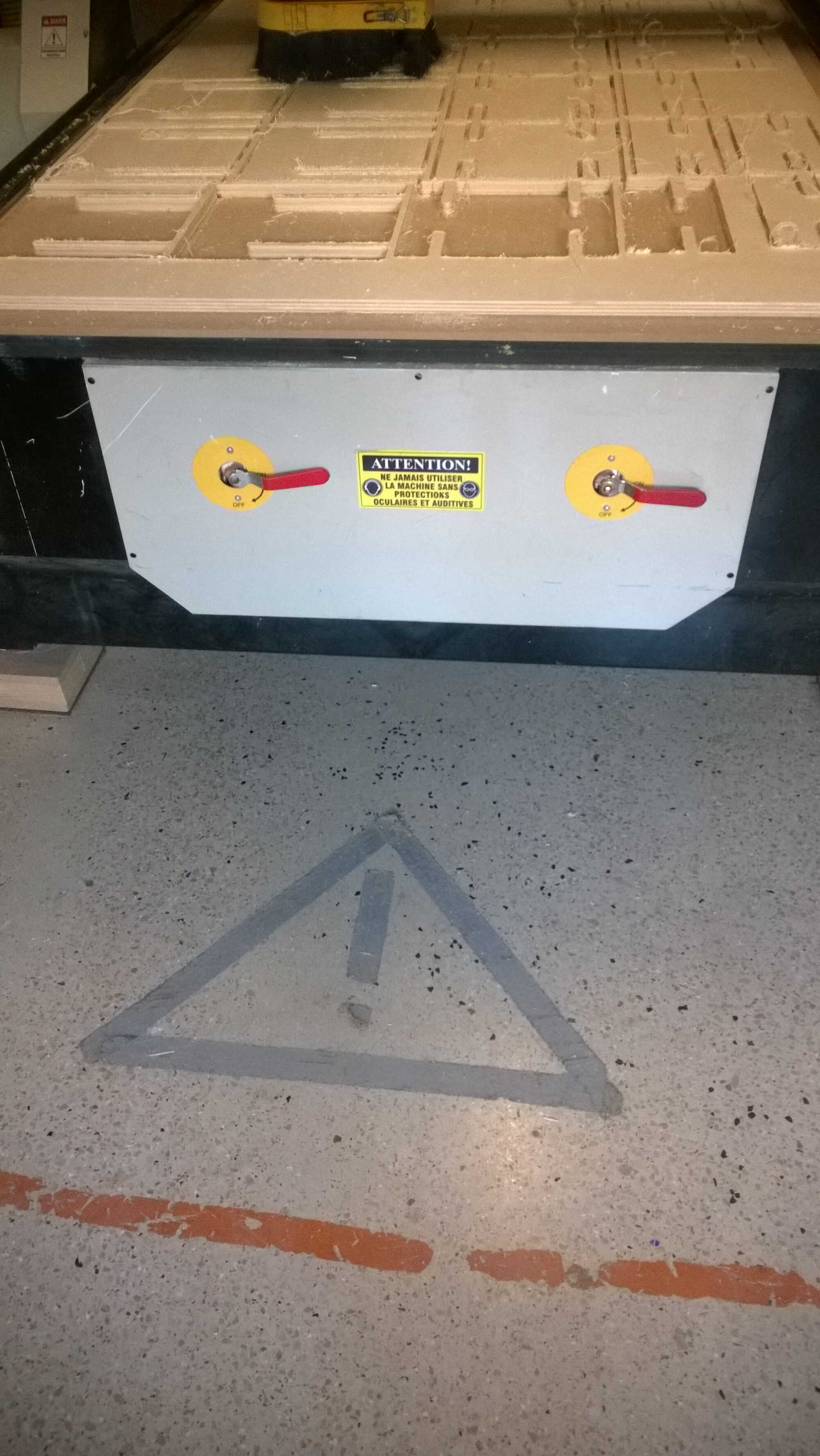
security distance
Milling
As I wanted to check the fitting I milled four pieces in a first place. First I didn't succeed in assembling them. I asked for help, Geoffrey at WoMa the furniture expert gave me a hand. Slowly but steadily -and with the extra help of a mallet and "levers"- the pieces could be assembled. I didn't forsee the need for some liberty degree. I considered adding an offset to the design to make the slots wider or a chamfer to facilitate to rotations.
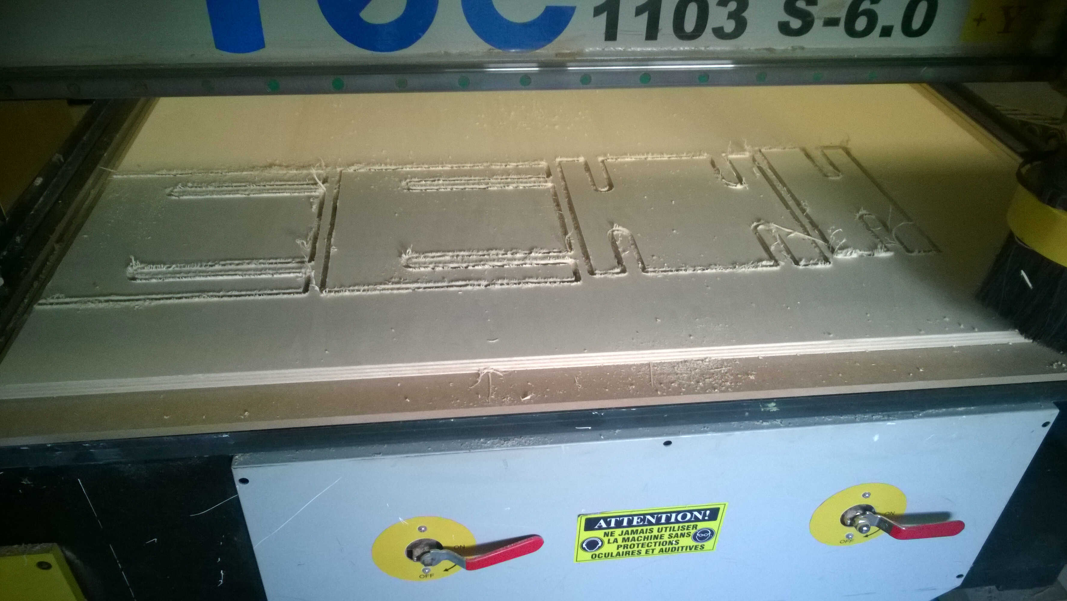
Milled first path
little help needed
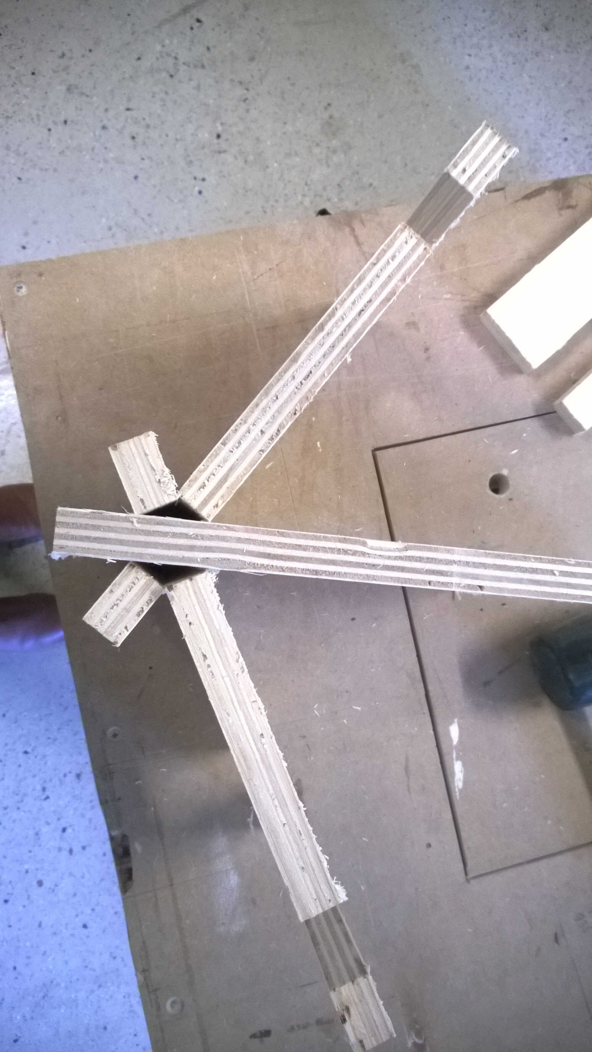
it finally worked
second path
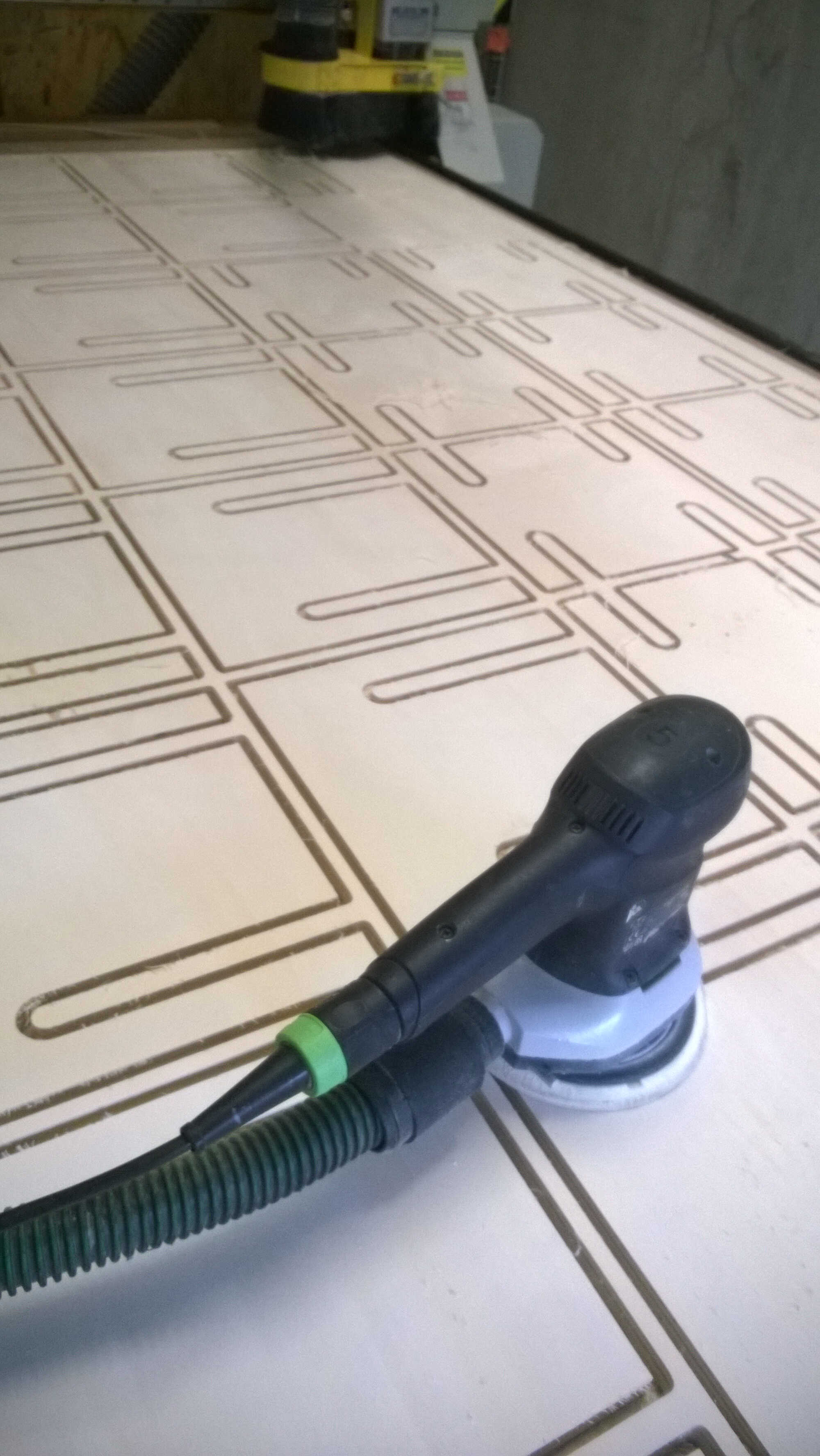
sanding
tab
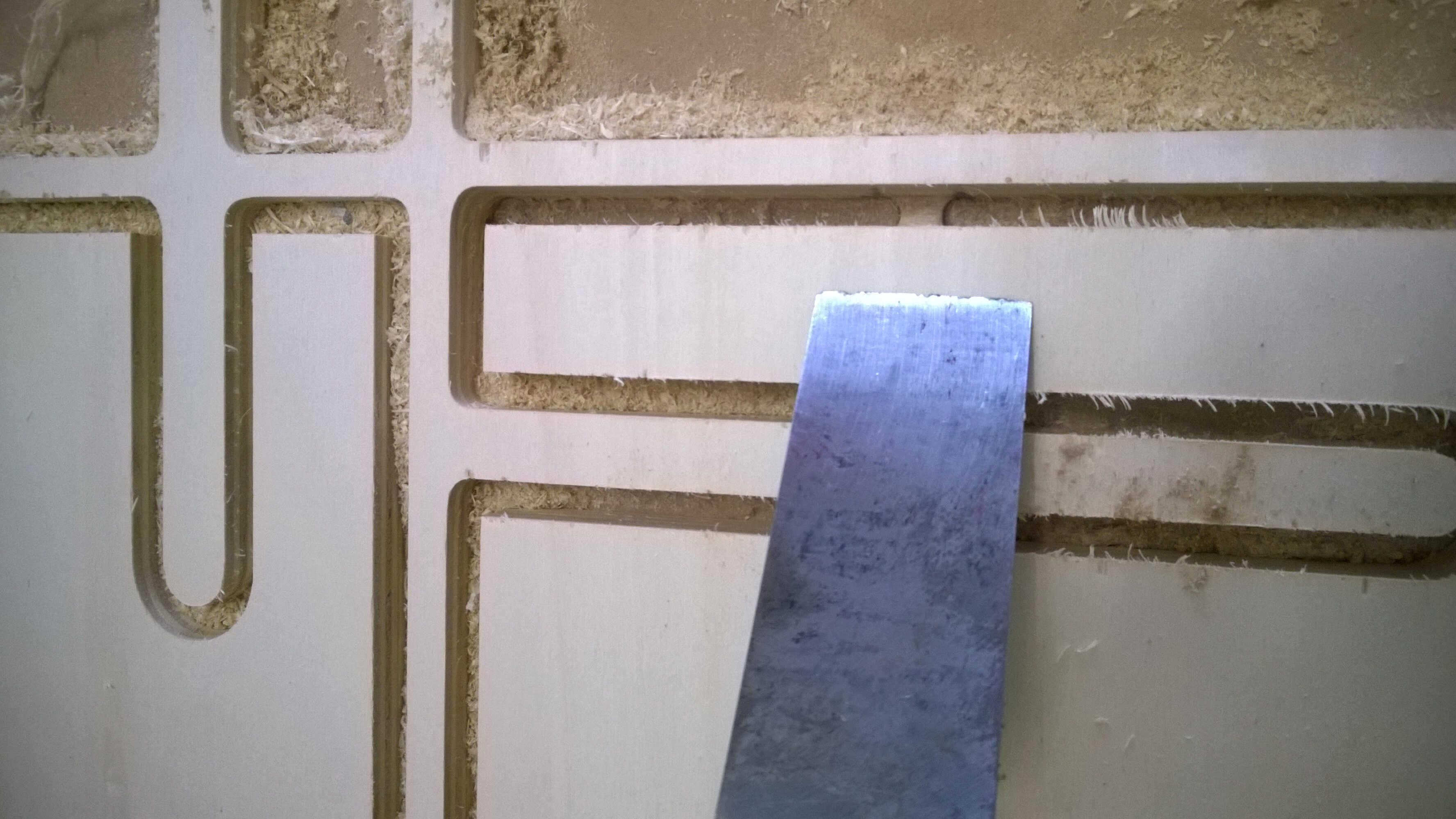
And action!
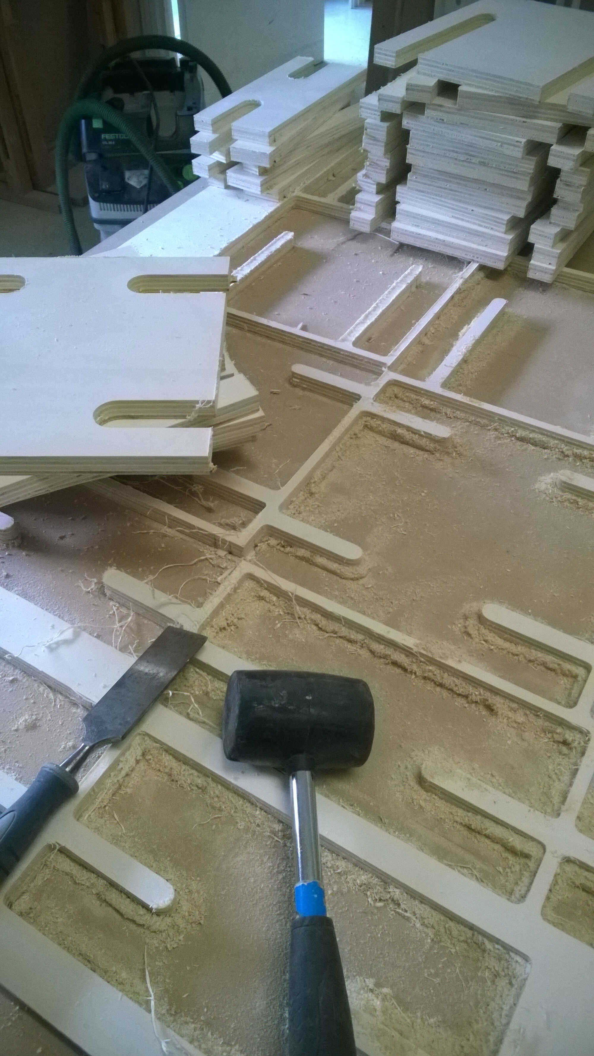
pieces extraction
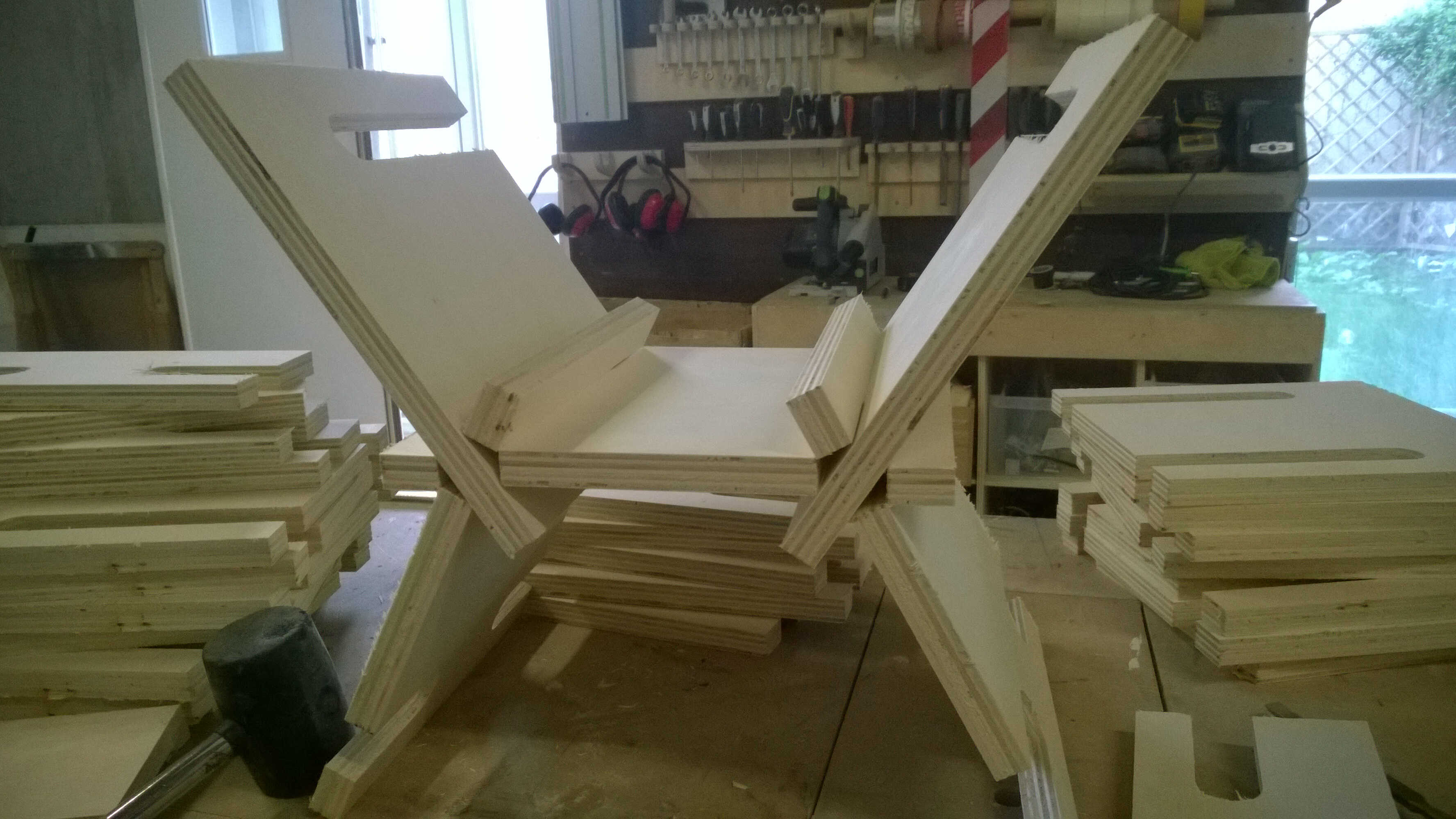
alternative assembling
Final result
Here a pic of the first 4 modules (out of 6) assembled. The milling consummed nearly all the board. I considered keeping the leftovers but WoMa manager pointed out that such small pieces wouldn't fit -and get fixed- on the CNC.
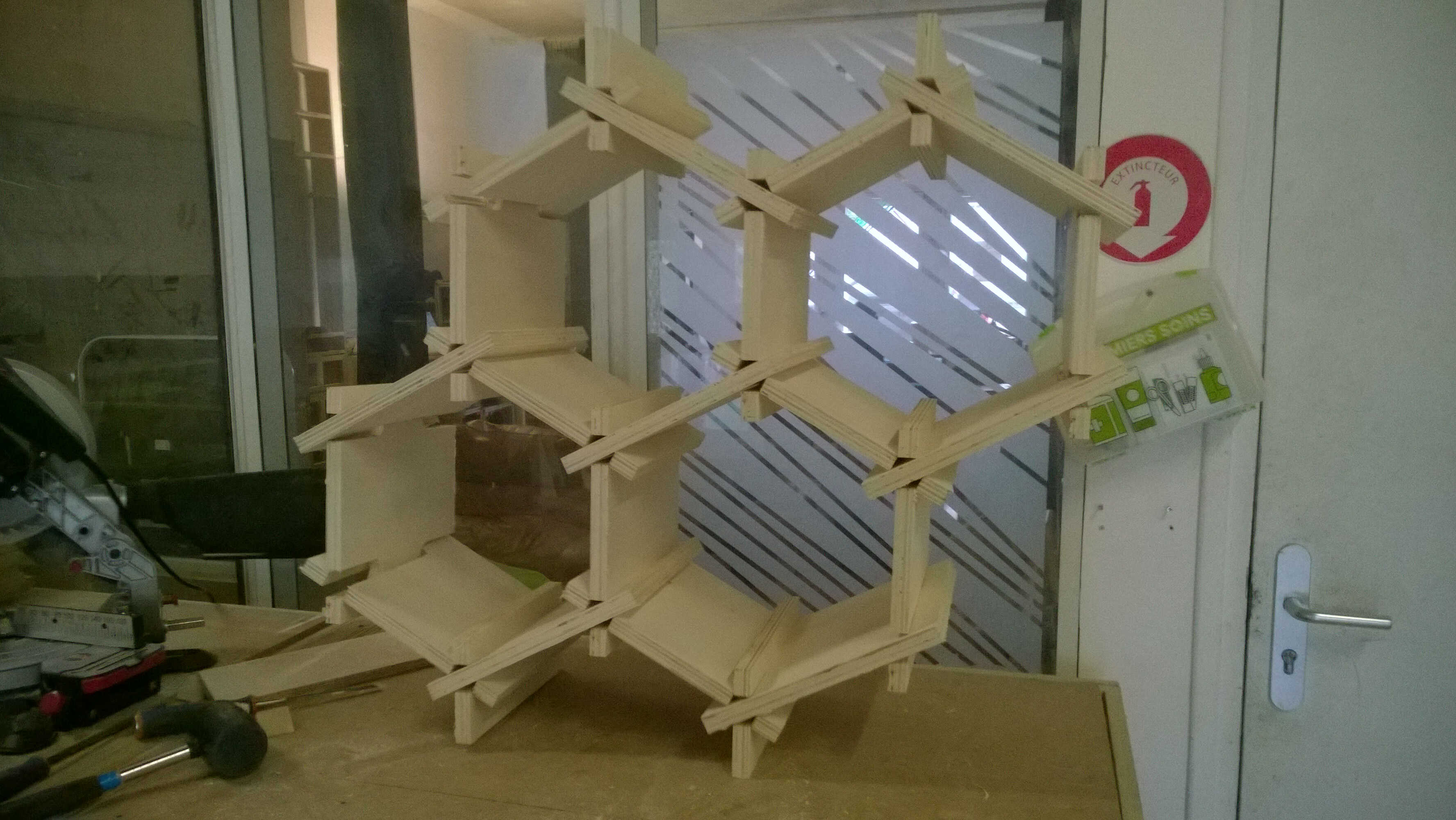
assembled hive
leftovers
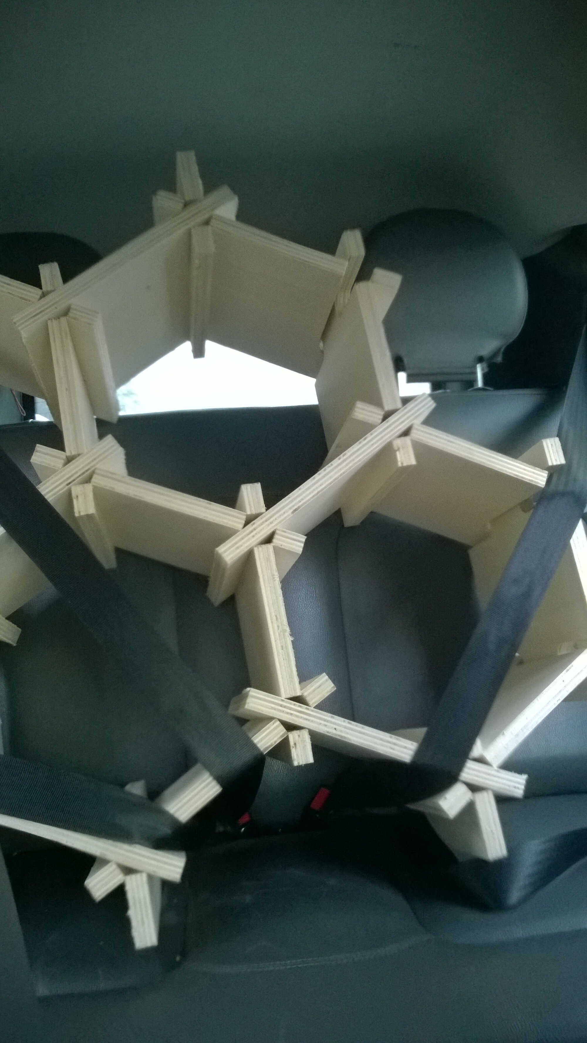
brought back home safely
Ideas to deepen:
-
-
Questions raised:
-
-
Energy harvesting:
- Is it possible to harvest energy from the CNC vibrations?
-
Eco-conception:
- Maximize use of the material
- Multi-fonction furniture
- Design thinking:
Biomimicry:
-Beehive-mimicry
Innovation management:
Personnal feedback:
- Good project no need for addition
Regional review:
CNC
- CAM with Fusion also exist for Rhino
- Show gcode
- Check output dimension with caliper to check loss
- If assembly tricky engrave the piece to recognize them
- Dogbone pluggin in Fusion
- VRay Rhino pluggin for rendering
Website
-
General review:
Week related observations
-
Website
-
Final project
- Bioresins