Abstract
This week was about 3D, about how to capture three dimensional objects as well as how to design in 3D.
The question raised were:
- What kind of object can I scan and at which resolution?
- What are the limitations of a 3D printer?
- What parameters are crucial for the printing process?
- What inter-sofware workflow to pick? For which purpose?
After a week investigating, I observed that the limitations to scanning are mostly related to computation capacities.
This makes Remake a prime tool as the computations can be done on the Cloud.
3D printers are more limited, at least the fusion molted ones. Carbon3d opens great perspectives.
The printing process can be correlated to the head speed and the filament extrusion.
Great care should be taken as soon as meshes are involved. Workflows with bodies are way more quick to travel through than those with meshes.
I tested 3 different workflows:
- Skanect > Print Studio > Slic3r >Pronterface
- Fusion > Slic3r > Pronterface
- Remake > MeshMixer > Print Studio > Sli3r > Pronterface
My biggest achievement: The discovery of the scanning process
My biggest struggle: Mesh manipulation and Voronoi meshes printing
Chronology
| Thursday | Friday | Monday | Tuesday |
|---|---|---|---|
| Kinect Scanning (Car toy and myself) | Test design (overhang) | 3D printing (myself) | Meshes manipulations (myself) |
| 3D printer demo | Printing tests | Documentation | Test design and printing (angles) |
| Photogrammetry (stuffed Totoro) | Photogrammetry (camera- personal assignement) | Struggle to print my assignement | |
| Documentation |
Setup
| Softwares | Fonction |
|---|---|
| Skanect | 3D scanning with Xbox Kinect |
| Autodesk Remake | Photogrammetry |
| Autodesk Print Studio | Slicing software |
| Slic3r | Slicing software |
| Pronterface | Interface sliced model/3D printer |
| MeshMixer | Mesh reworking |
Skills acquired
Asssesment validation
The first day of 3D week, we had the chance to be invited at Sculpteo's event dedicated to Carbon3D's technology CLIP-hosted at WoMa. CLIP is similar to stereolithography, except that the printing is continous and that it's a double cured process. The materials gain their final properties and their isotropy when reheated. Some examples were displayed:
The high definition of the samples was impressive, they were soft and resilient. Most were made out of flexible polyurethan elastomers.
With those, Carbon3D aims at making 3D printing a manufacturing process.
Here the basics of CLIP technology and its unveiling by its founder, Joseph DeSimone, at TED:
It would be nice to be able to test this printing technique.
We started the scanning practice with Kinect 360. First we wanted to scan a small toy car. We got inspiration from this Youtube video:
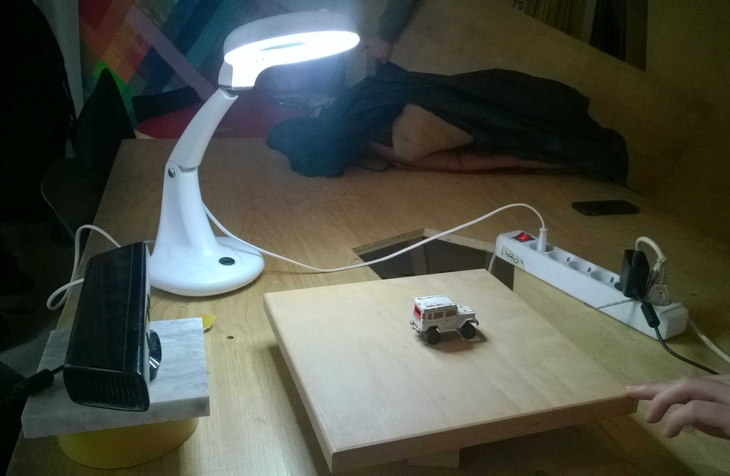
setup
wrong focus -too close-
better focus
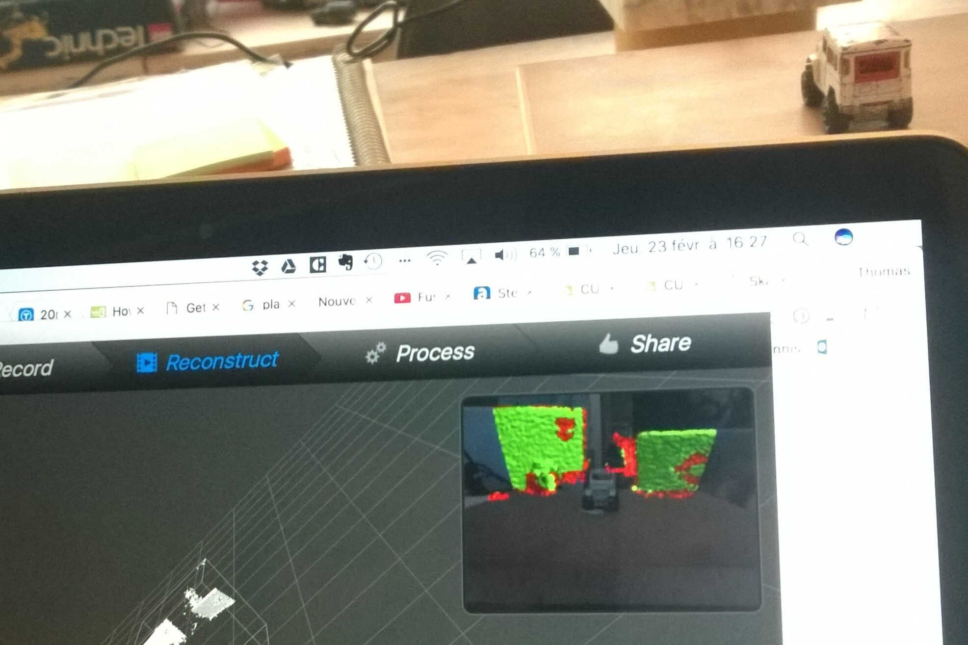
Thanks to this video we solved focus issues. We couldn't get a good scan of the car probably because some Kinects showed defects.
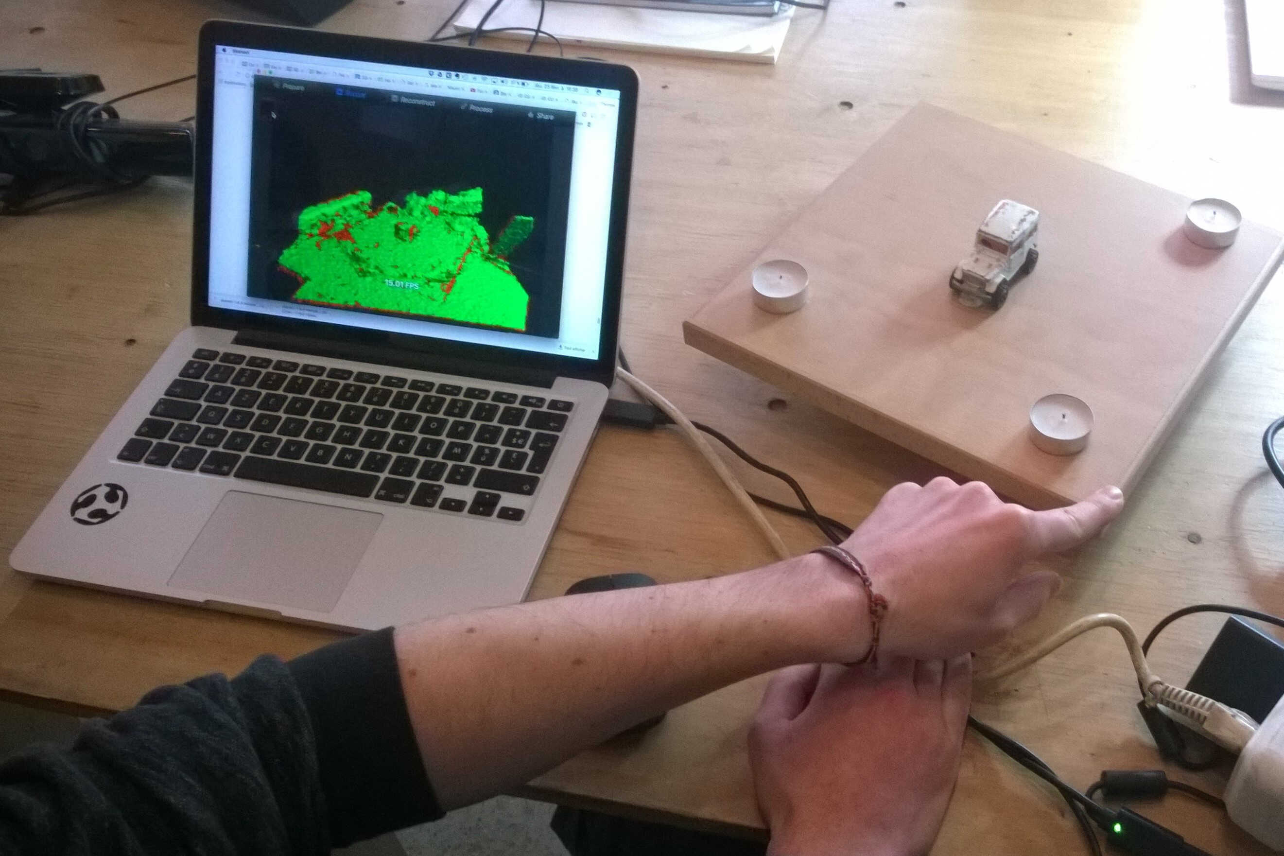
At the end of the day we managed to scan me with Thomas Mac and the working Kinect. Thomas turned aruound me using the Kinect as a brush.
The scanning show some defects, for example I have 2 noses.
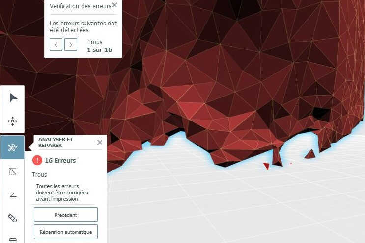
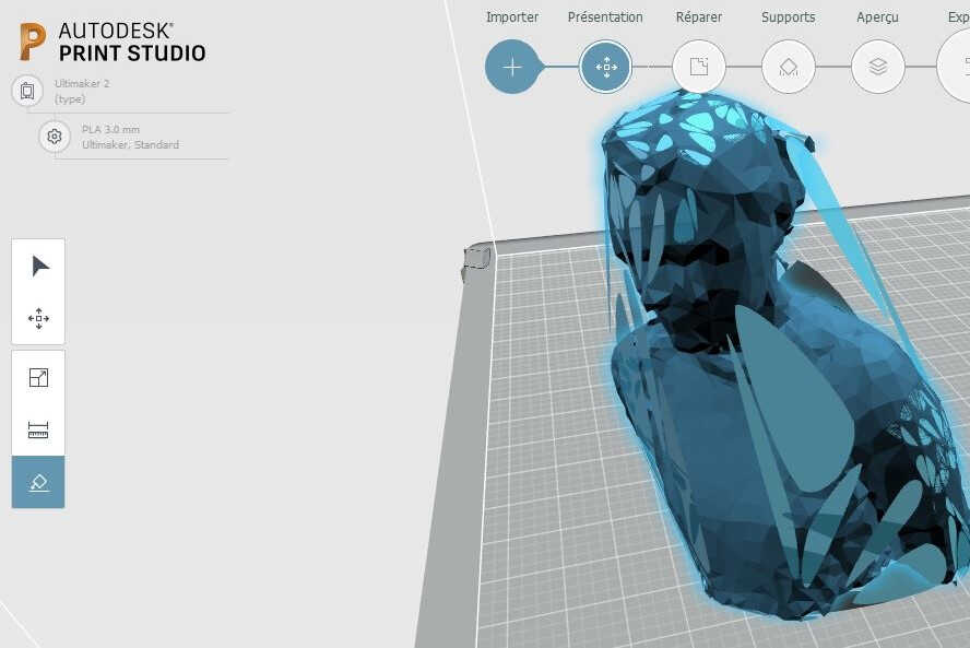
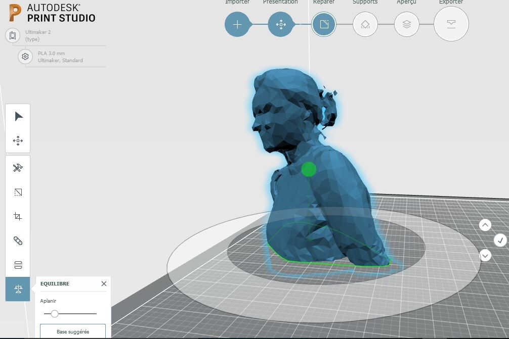
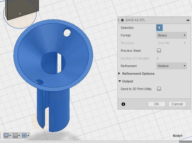
I tried to open this .stl in Fusion 360 and with Slic3r, both softs struggled. I finally opened it in Print Studio, which detected numerous errors in the geometry.
As long as the error remain the model is displayed in red.
1. Those errors were automatically corrected with the Repair option. When looking in details the errors are mainly isolated mesh triangles.
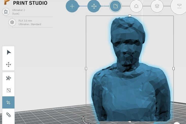
2. The model was made flat, with the Make it flat option.
3. Geometrical anomalies -floating pieces for example- were removed with the lasso.
4. The base of the model was made even with the trim option.
5. An alternative to the 4th step is to use the equilibrium option.
I printed this model a few days later.
repair the model
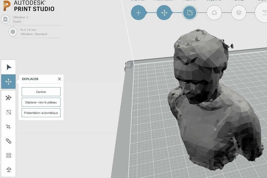
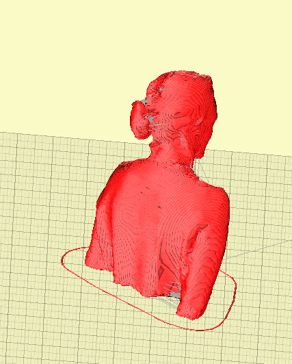
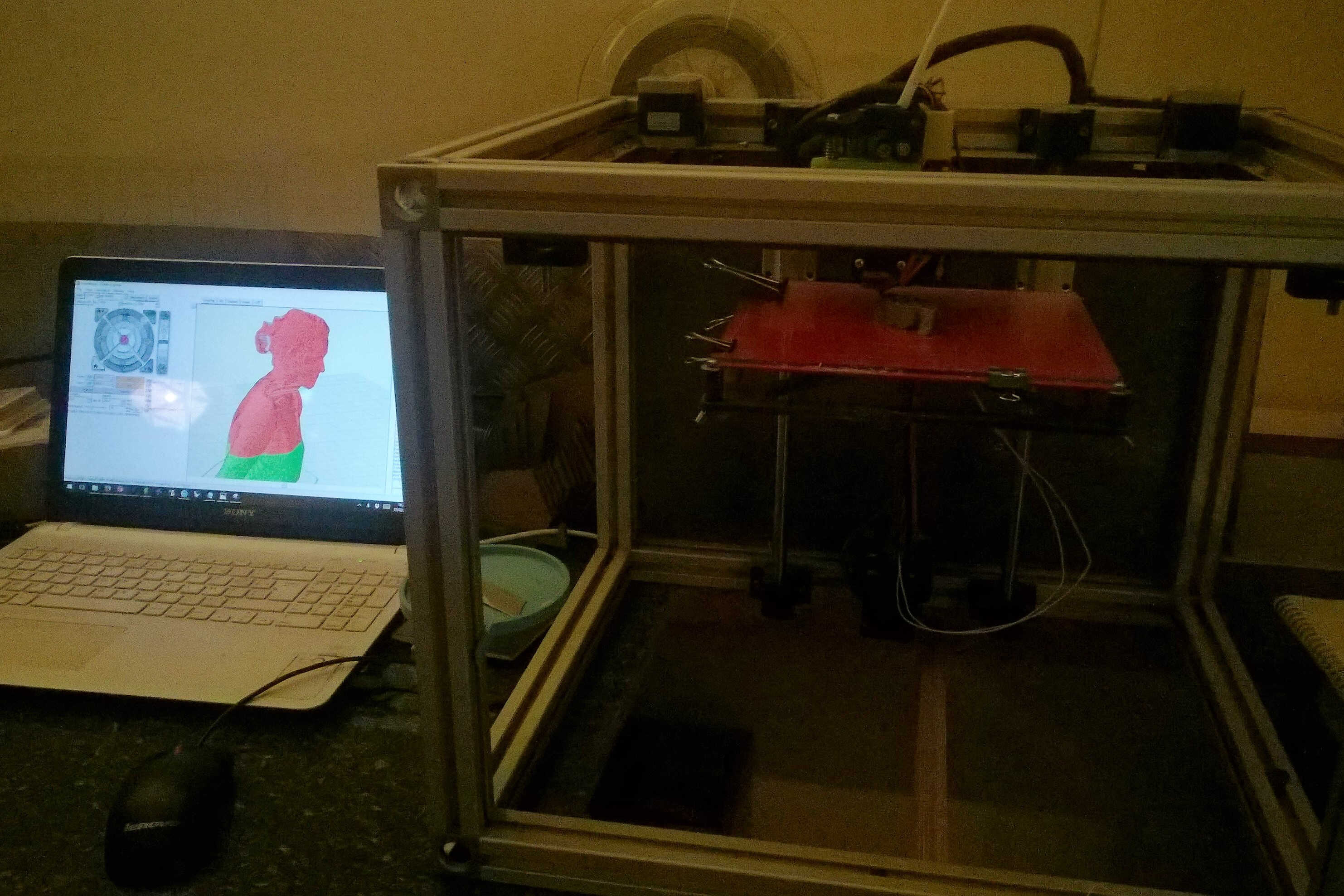
Skanect 3D scan of myself
flatten the model by selecting one of its plane
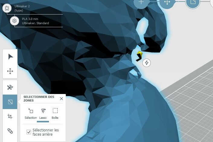
cleaning the model with the lasso
even base
equilibrium
Source file to load here
Practice
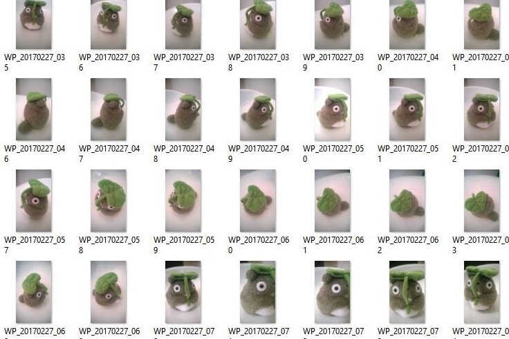
As I do not have a Mac I switched to Remake and to its photogrammetry solution. My first attempts were unsuccessfull. I watched a couple of Autodesk tutorials, to understand what I made wrong:
I came to the conclusion that I previously took too few pictures of my model-a stuffed Totoro. Some elements could also be added to be used as reference points.
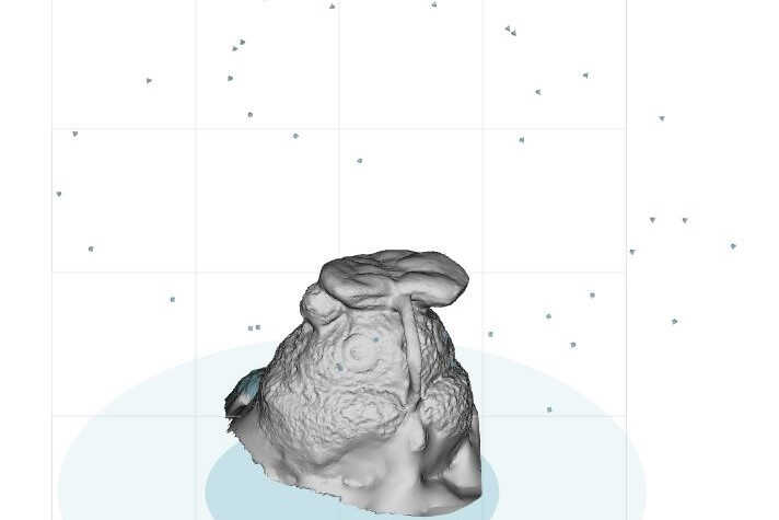
For my next try I used a white -slightly reflecting- turning chair as support. 40 photos were used. Remake could then coompute a model.
The definition was correct, using a stuffed animal won't provide a smooth model anyway.
Surplus part could be removed with the Delete Selection tool.
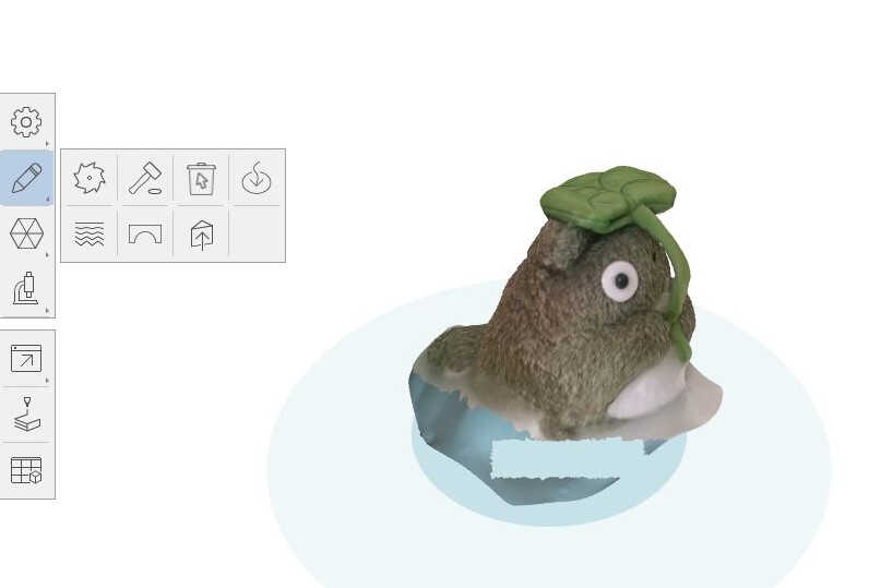
The bottom of the model was void as no picture from below was taken. The model needed to be closed. Remake suggest 2 options: flat and smooth hole filling.
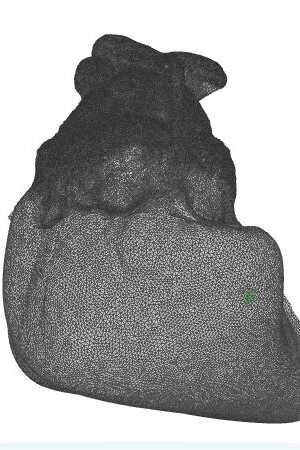
It is possible to visualize the mesh by selecting the view: Solid with Wireframe. Here we can see that the mesh is fine.
photoshoot
camera position reconstruction
cleaning the model
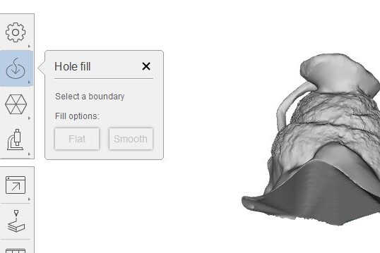
flat hole filling
smooth hole filling
high definition mesh
Source file to load here
Assignement
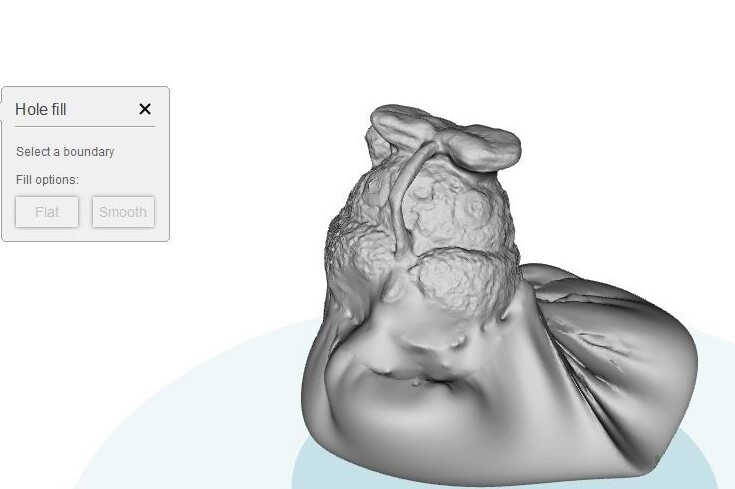
As I enjoyed this scanning process I decided to use it as a base for my personal object. Also I printed the output of Skanect why not compare with photogrammetry? I then scanned one of my analog camera a Yashica Mat 125. I reached Remake limitation for the free version: 50 pictures max. Remake successfully computed a model, once again -even if bottom pictures were provided- the bottom was void. I chose the smooth hole filling as this adds some poetry to the shape, evocating a cloud.
photoshoot
cloud computating over
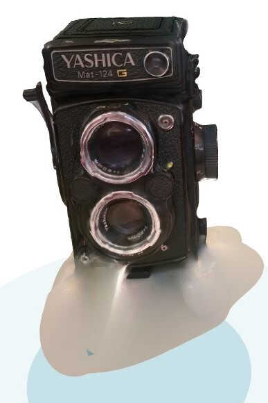
Remake model filled
My first idea was to make the camera hollow and to insert another object into it.
To do so, I thought I could export from Remake a mesh or an object.
Convert my export into a body and then use the Shell tool in Fusion 360. I struggled to follow this script.
First I had to understand the export format from Remake (stl or quads).
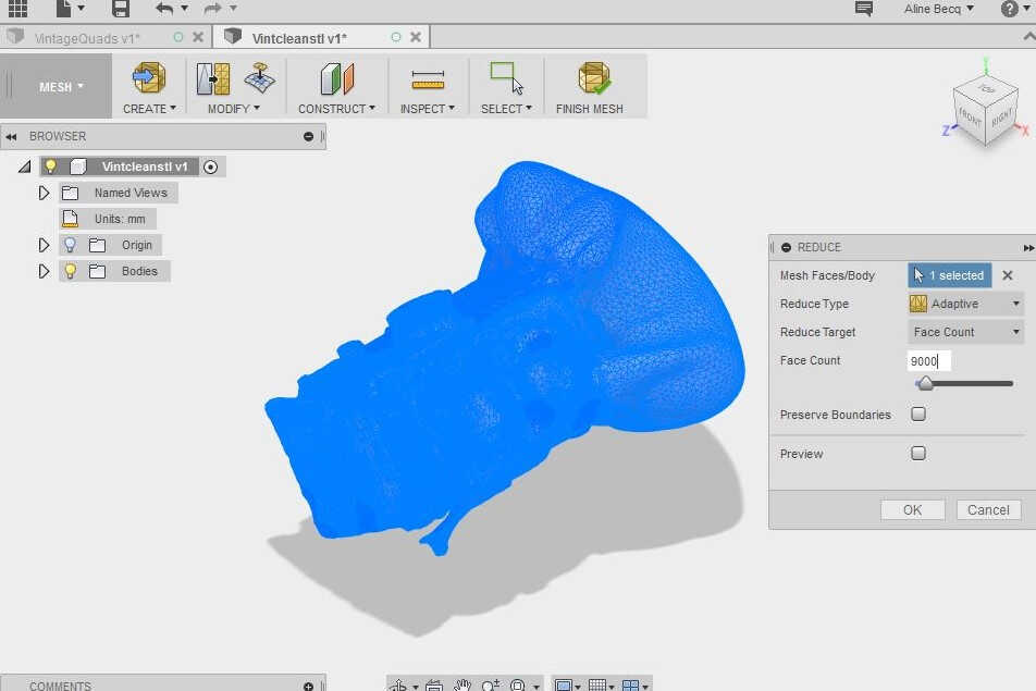
In Fusion meshes can be converted into body with the command Mesh to Brep. But I got some error message. I had to stumble into this tutorial to understand that my mesh was to fine:
Above 10 000 facets the conversion is hazardous. The mesh had to be reduced. There is a Mesh section in Fusion 360 that need to be activated in Preferences.
I noticed that the outputs were not really stable (didn't respect the facet count imposed).
I finally got my body in Fusion 360 but couldn't make the Shell option to work, probably because of all the facets. Fusion clearly struggled with the mesh size.
I looked for an alternative. In many mesh-related articles the soft MeshMixer was mentionned so I downloaded it.
The user experience with MeshMixer is far better than in Fusion 360. There are simple options to make a mesh hollow or to turn it into a body.
I watched tutorials about MeshMixer and some mentionned the Voronoi meshes.
This mesh seemed ideal, it was possible to see through and it minimalized the material and the printing time.
I decided to go for it.
mesh reduction in Fusion 360
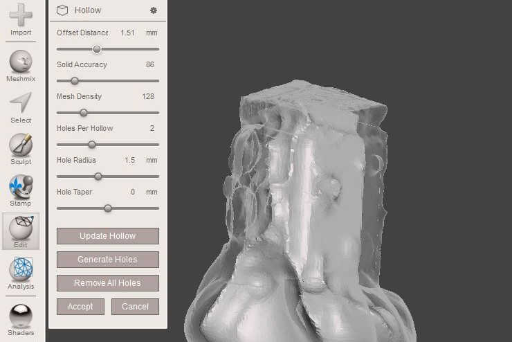
hollow option in MeshMixer
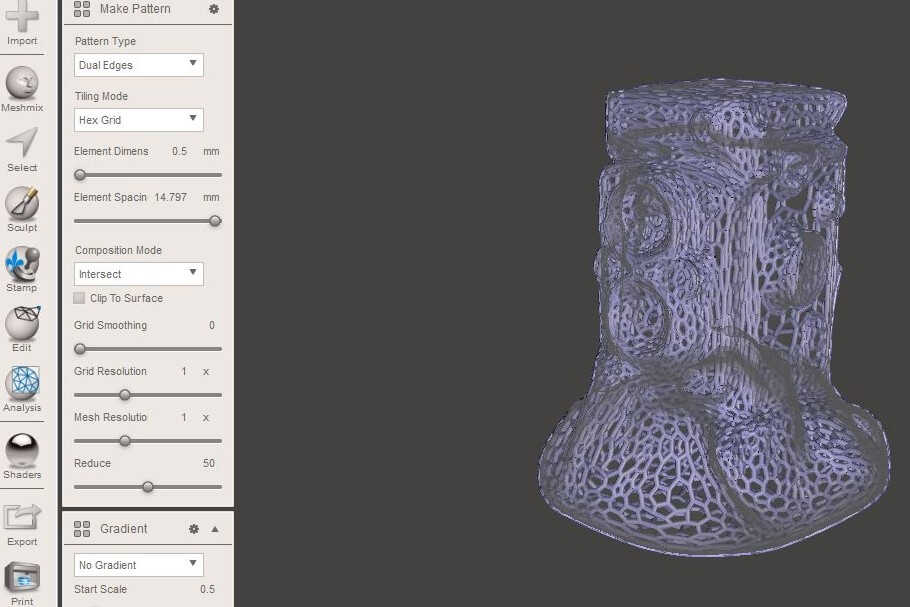
Voronoi
1. As indicated in the tutorial, I reduced mutiple times the mesh by 50%.
2. I selected the Make Pattern option.
3. I displaced the cursors to element high spacing and small dimension.
4. I computed by pressing enter
5. I exported the result as .STL
6. I cut the base of the model to make it stand upright with the Equilibrium option of Print.
7. I loaded the model in Slicr.
8. I increased the scale in order to have multiplayer deposits at each spot in the Layer view
9. I exported the gcode
10. I tried to print with the Speed at 50% in Pronterface. It is to be noticed that I crashed my computer a couple of time as the mesh was consequent
Source file to load here
Basics
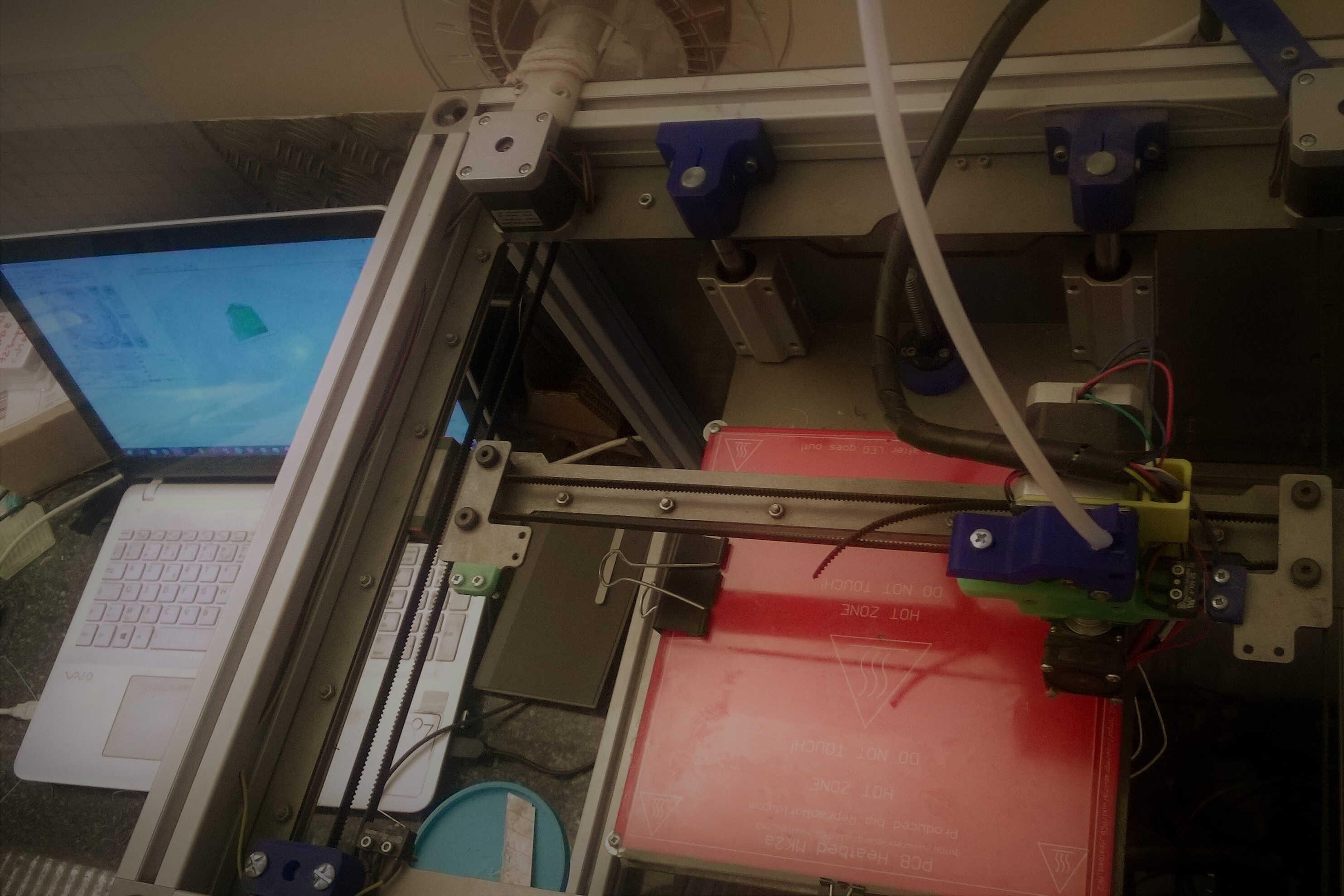
The 3D Printer we are using is a DOM Printer by Dood Studio, working with 1.75 mm filament. It is based on RepRap.
In order to change the filament the extruder head need to be warmed up, Pronterface Extrude/Reverse commands are then used to introduce/remove the filament.
Here we used a 0.4mm nozzle but it is interchangeable.
The printing sequence is:
1. Warm up the bed(60°) and the extruder (190°)
2. Import your .stl file in Slic3r
3. Check the layers and input the printing parameters and export to gcode
4. Clean the bed with the cutter to remove plastic residues
5. Spray some hair spray to maximizee the adherence
6. Test the extruder head by clicking on extrude. If some melted plastic drop, it's ok.
7. Load your gcode into Pronterface
8. Click on Print
The not-yet-printed layers appear in red, the printed one in green.
Dood 3d printer
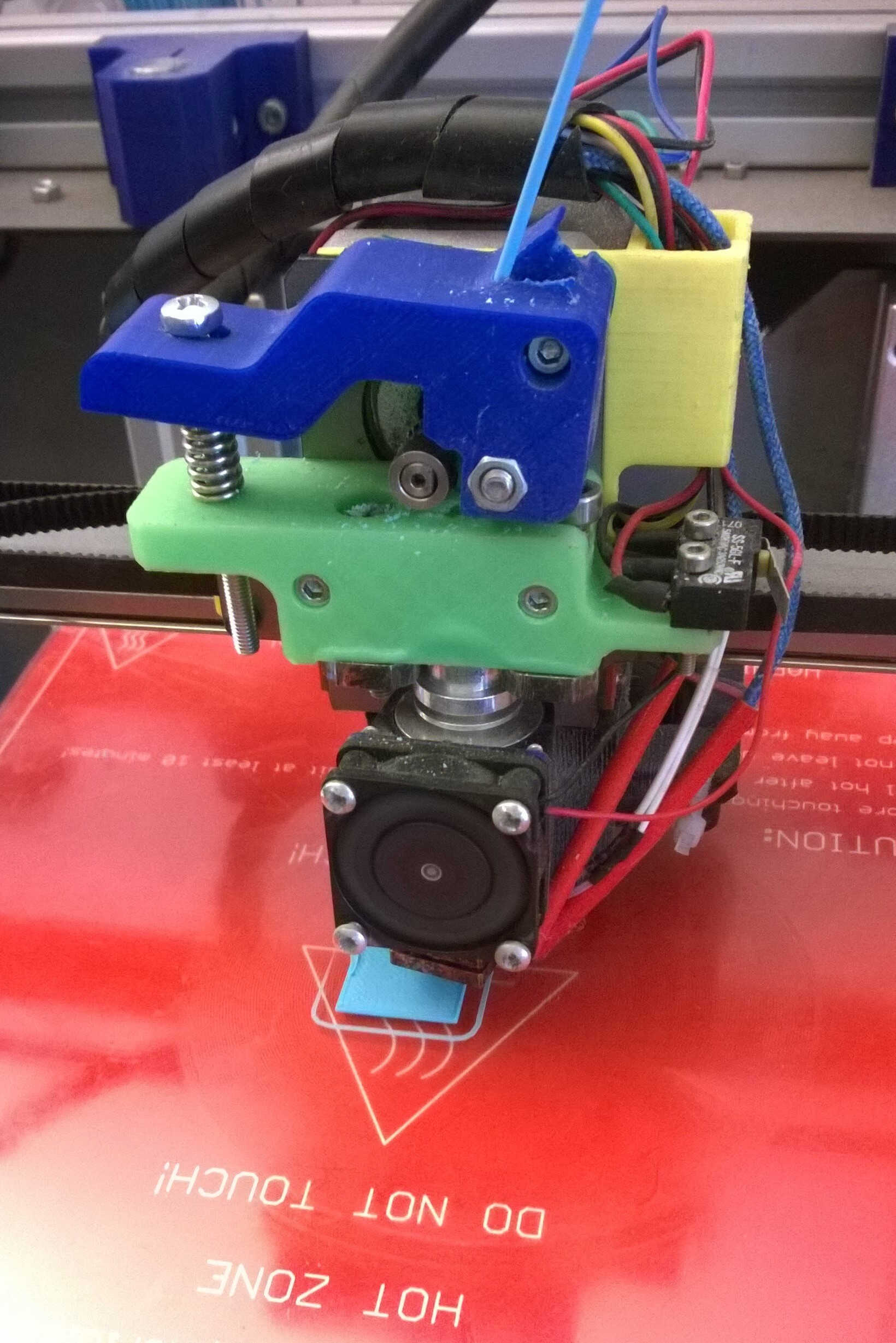
Extruder
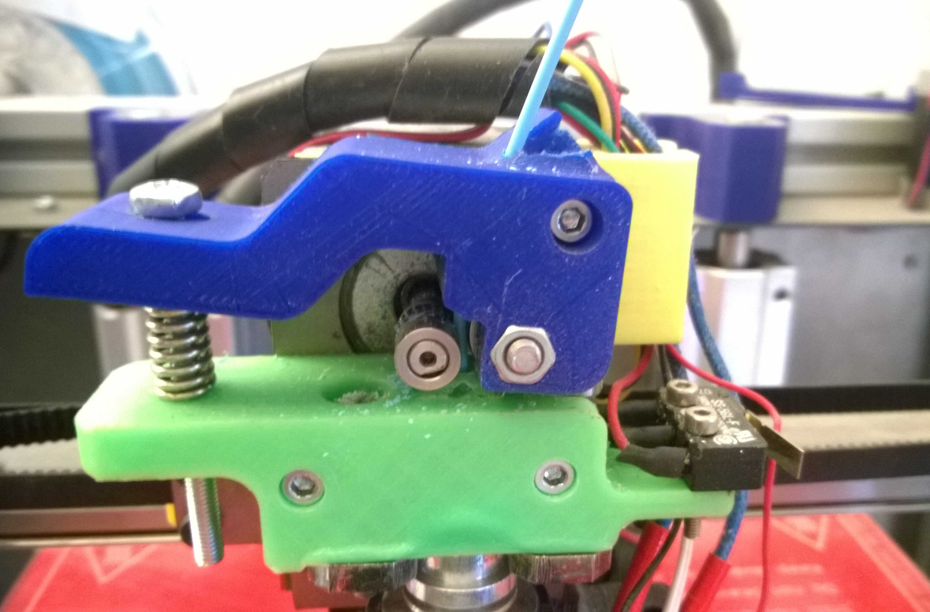
filament
Group assignement
For group assignement we were asked to test our printer limitation with proprietary designs. As inspiration we looked at test models on Thingiverse or Make magazine evaluation. We divided the tasks and went for testing design limits. I started to design to test maximum angular overhang with Fusion.
Overhang
Inclined walls mimicking dominos were sketched. Thomas suggested to use the same design to test pillar thickness limitation. I designed a comb-ish body to split my main body. The split generated some overhangs too. In Slic3r the model scale was reduced to 50%. The angles were conserved but the distances were divided by 2.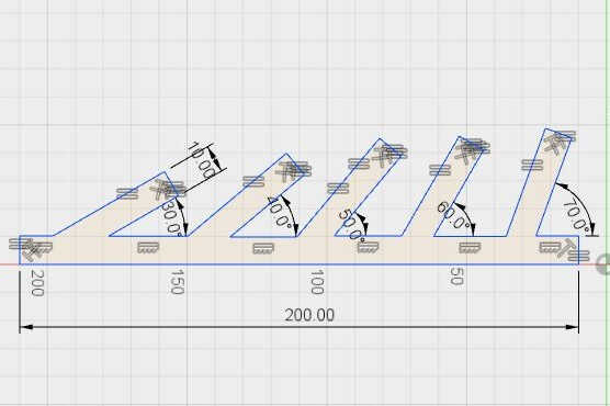
Fusion sketch
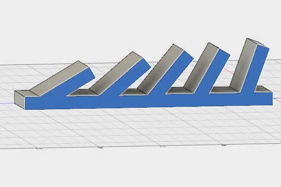
Fusion body
comb
Split bodies
Slic3r layer display
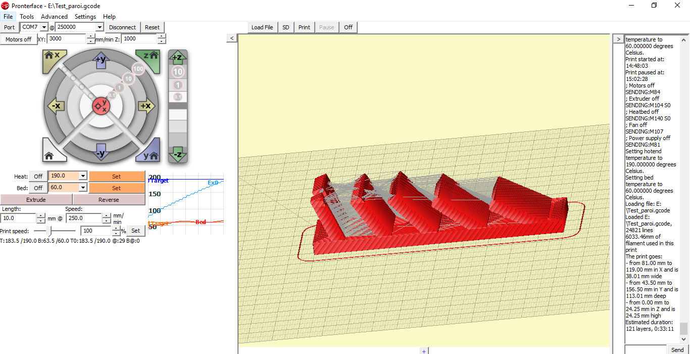
Pronterface visualization
The printed result showed us that as the slopes were progressive the printer could cope with all the slope (up to 30°). At 30° it nevertheless begins to show some irregularities. As for the pillar 1.5mm thick is printed without issue, even if the scar is more visible. It would be interesting to take this design back and decrease the slope angles.
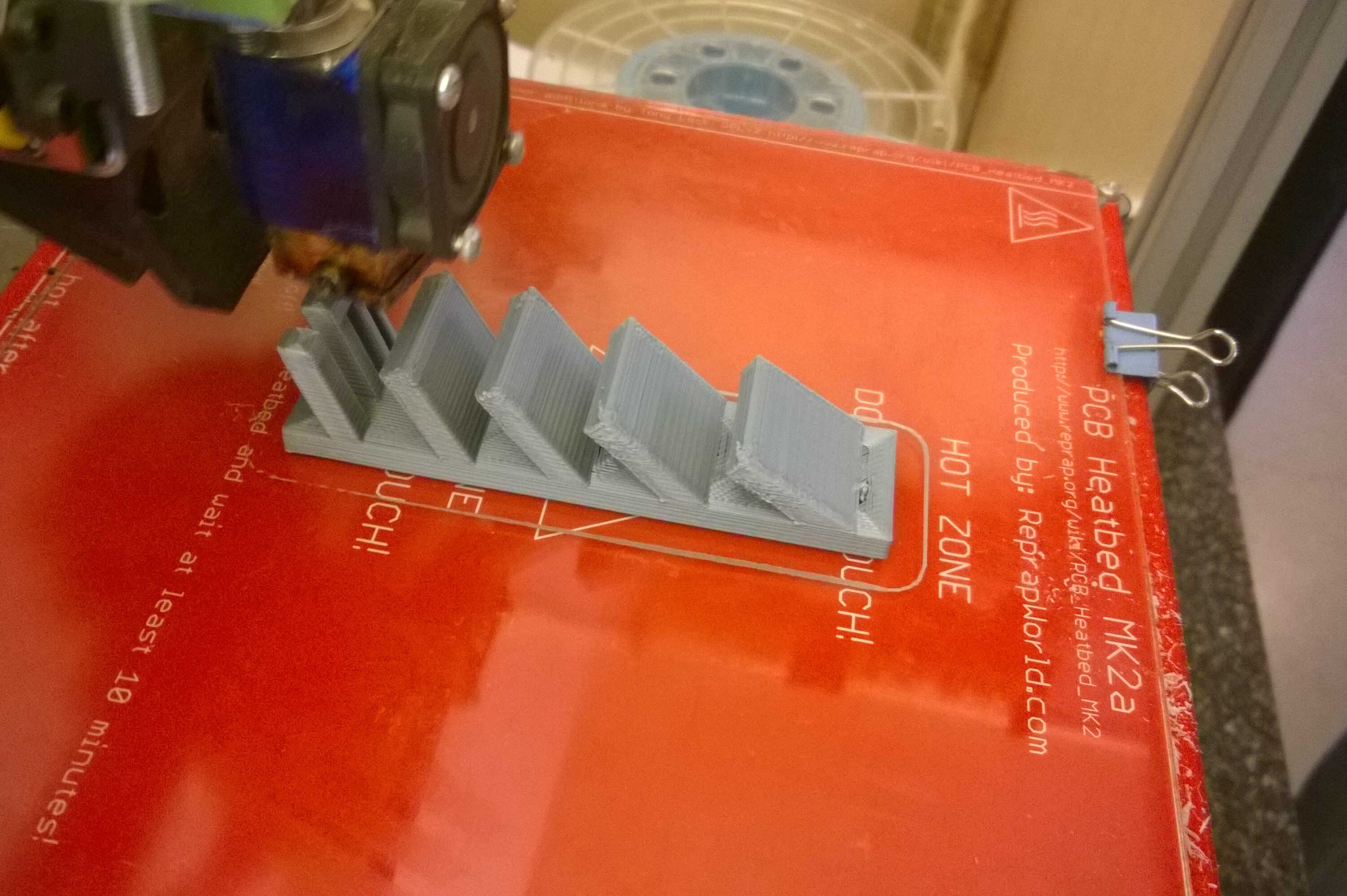
printed test
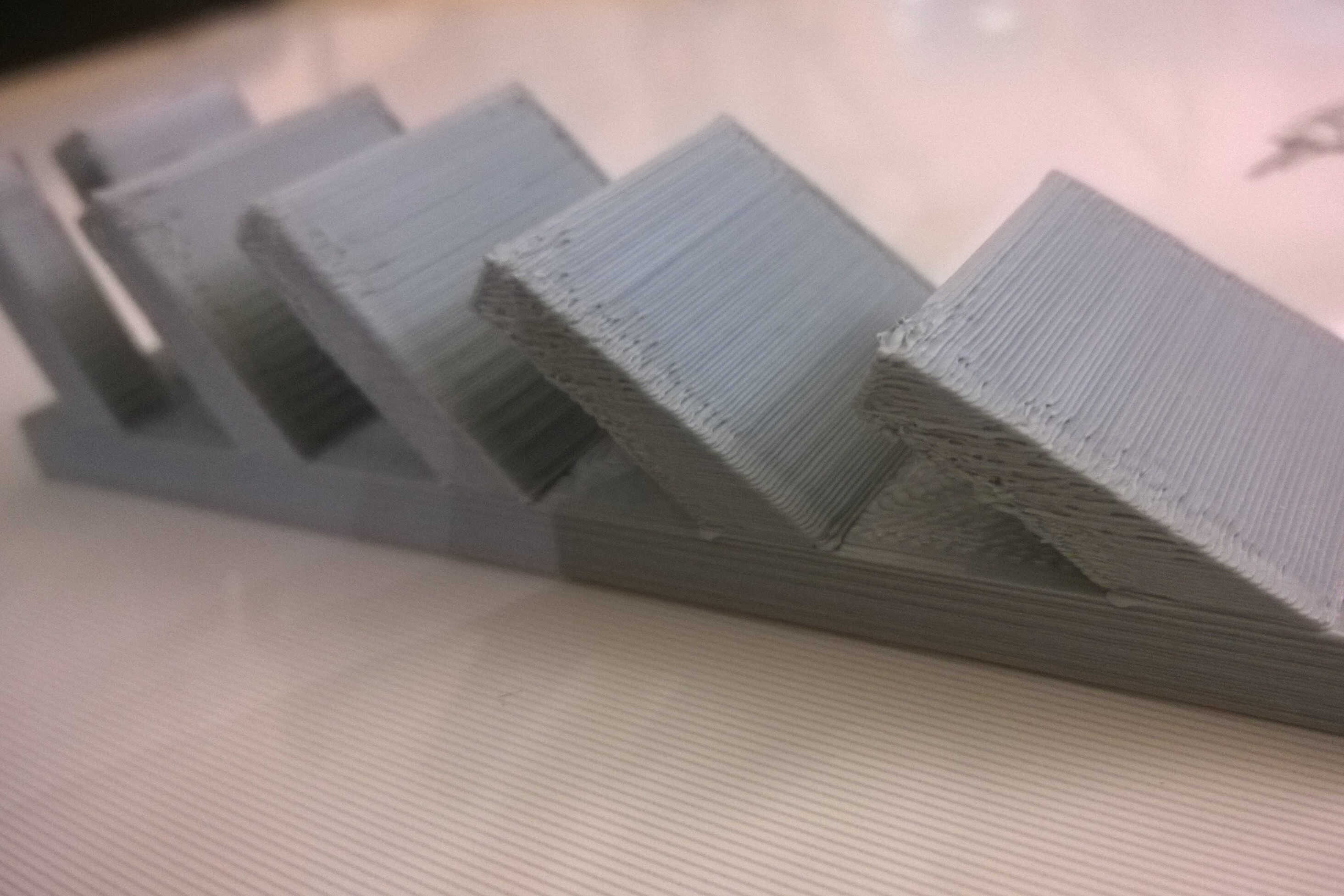
limit angle
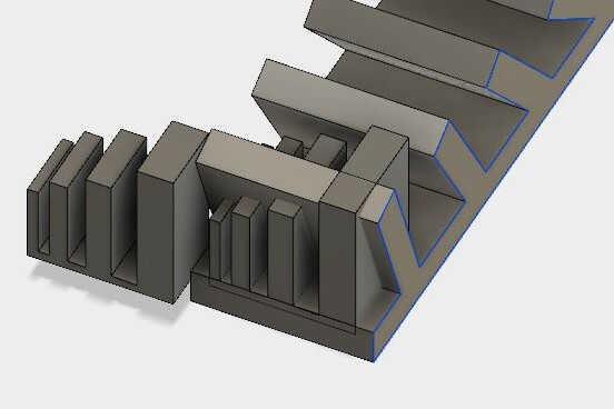
Wall thickness
Isabella designed a cross-test for wall thickness. Her showed that down to 0.4 mm-the nozzle diameter- the pillars did not collide.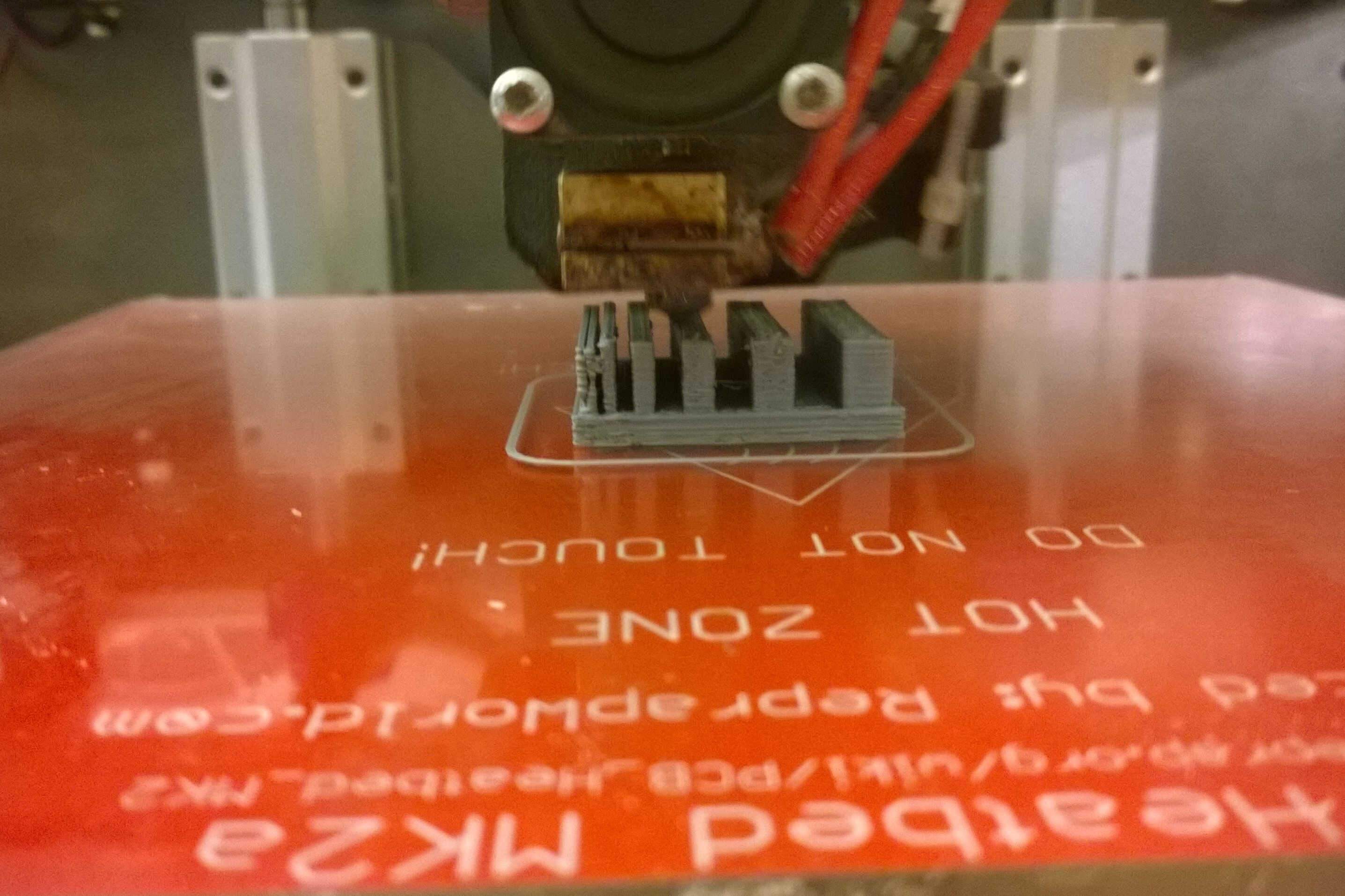
walls and nozzle
0.4mm as space limit
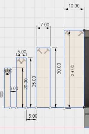
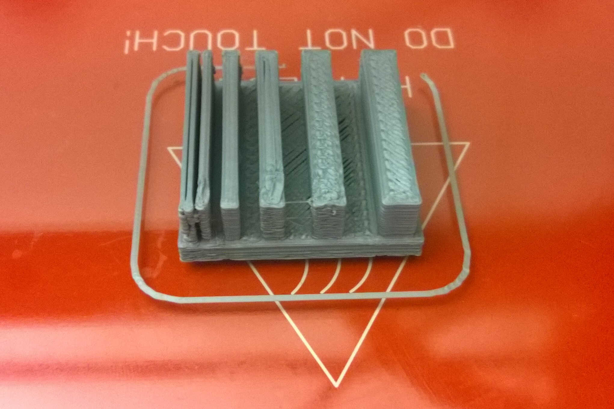
Angle sharpness
I designed a stack of triangular bodies, each step was filleted 1 mm more than the lower one. The printed result showed regularity but even the lowest step was filleted. It would be of interest to reduce the sharpest angle (35° here) in a complementary test and to use other material. The filament used contained wood and its melting properties are quite different.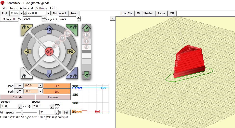
Pronterface visualization
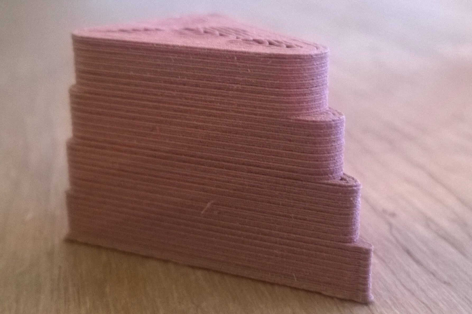
profile
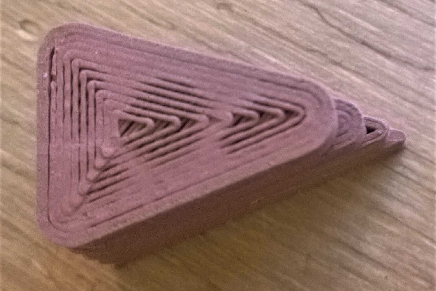
above
Tests source file to load here
Scanning printing
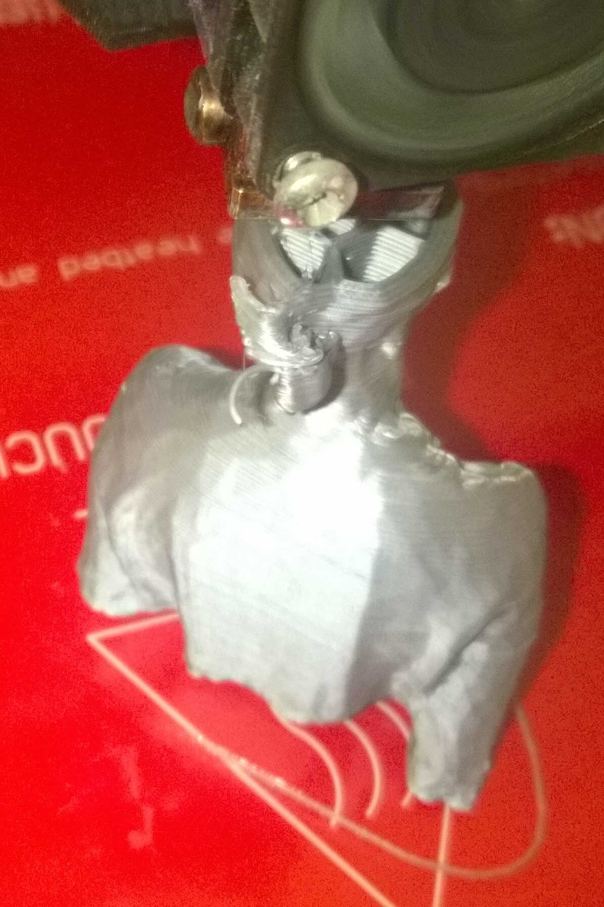
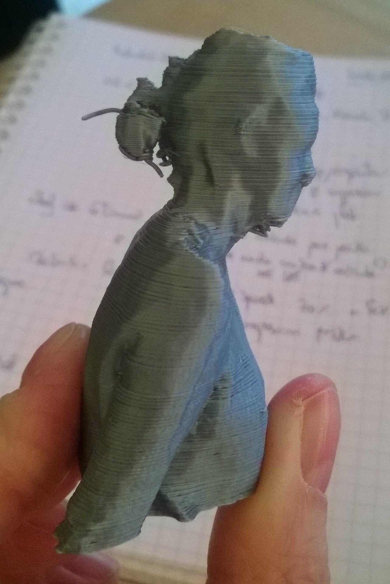
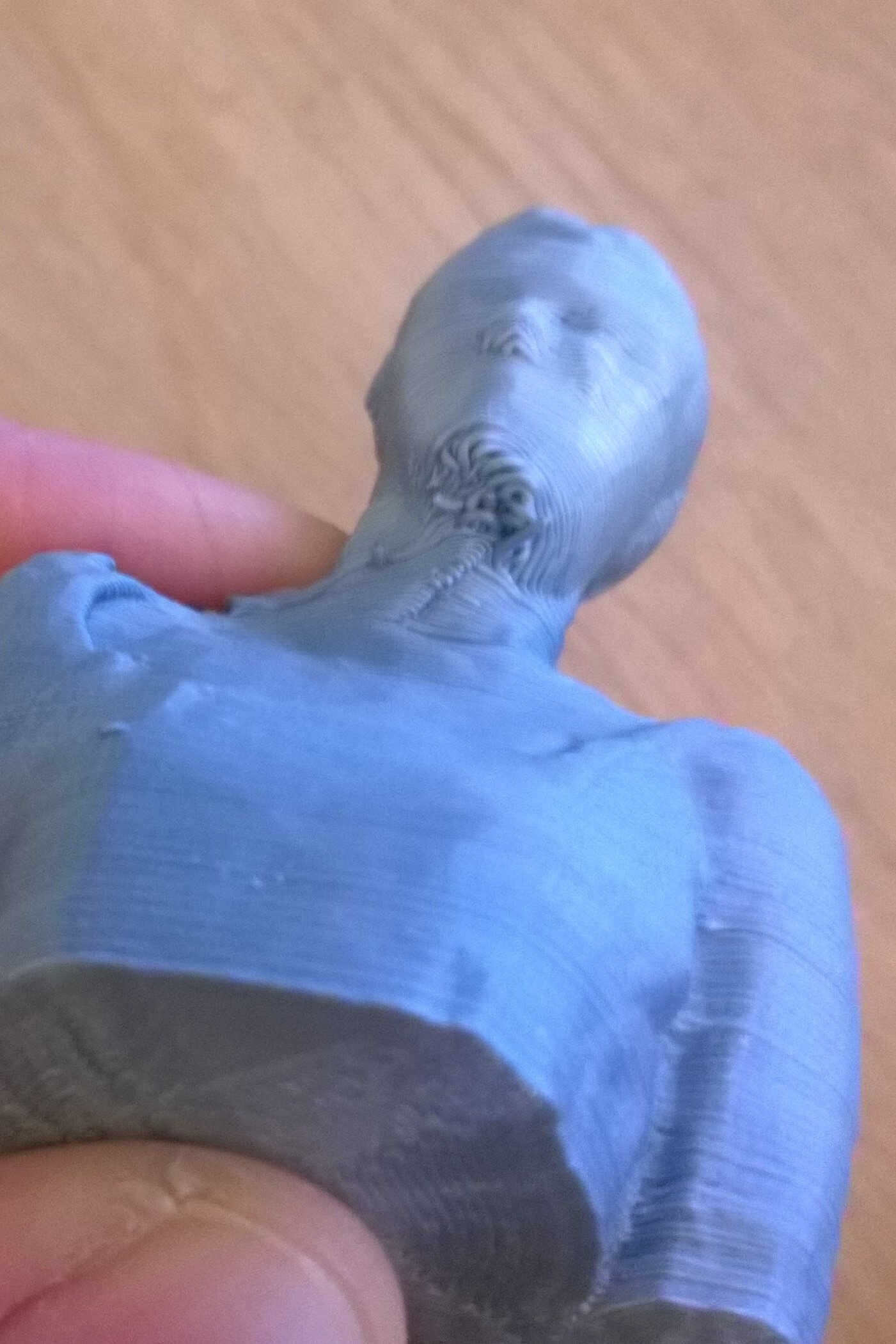
The first piece I wanted to print was my scanning. As previously evocated the file was reworked in Remake and Print. The printed bust was well defined, only 2 areas were uneven: the chin and the hair. I was wearing a poneytail during the shooting. Some hair showed overhang. I did not add support, the way the printer coped add some realism to the hairstyle. As for the chin I probably should have added a support or reduce the speed.
Pronterface visualization
progress
chin overhang issue
filling
done
chin from below
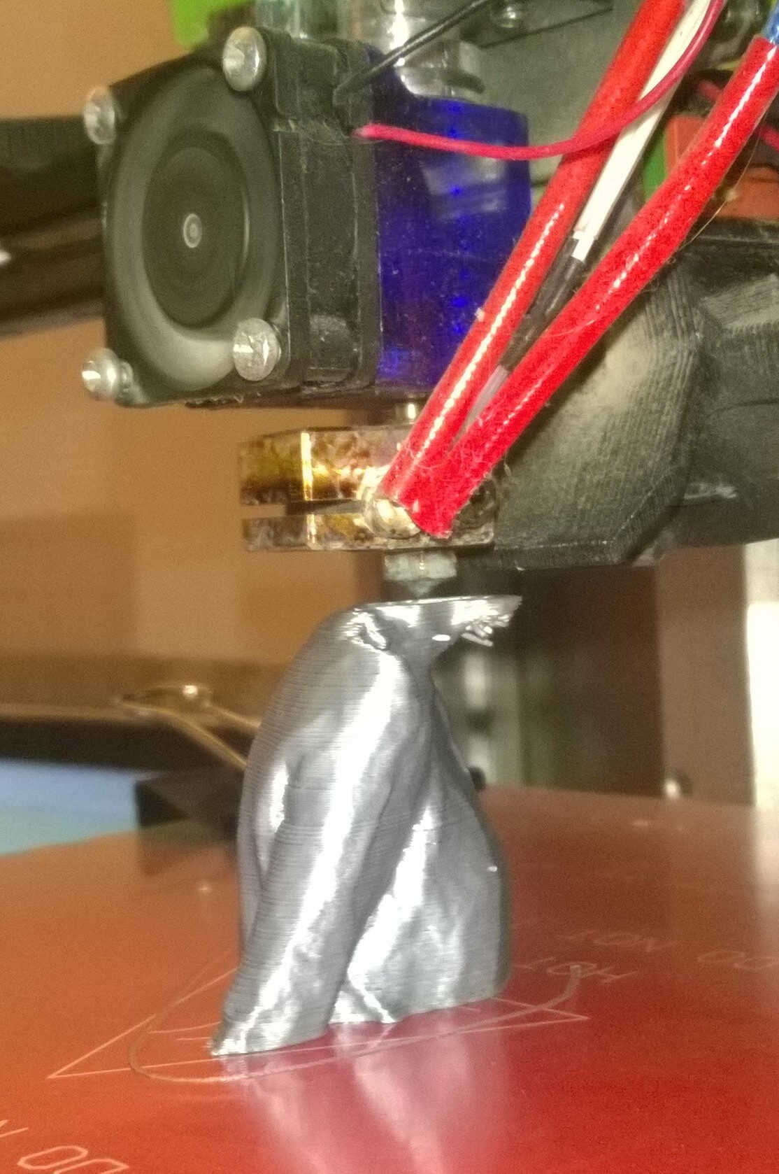
Creation printing
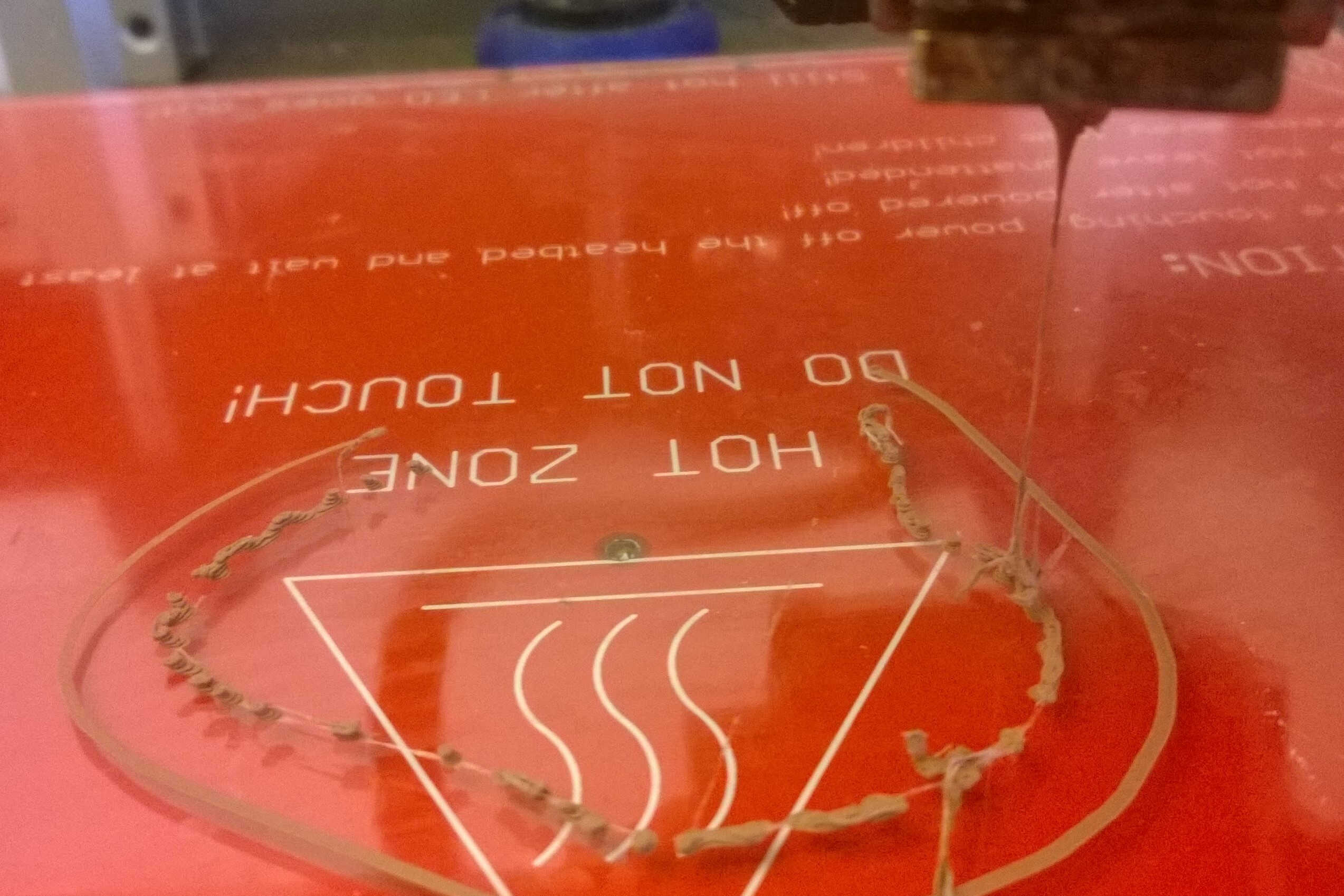
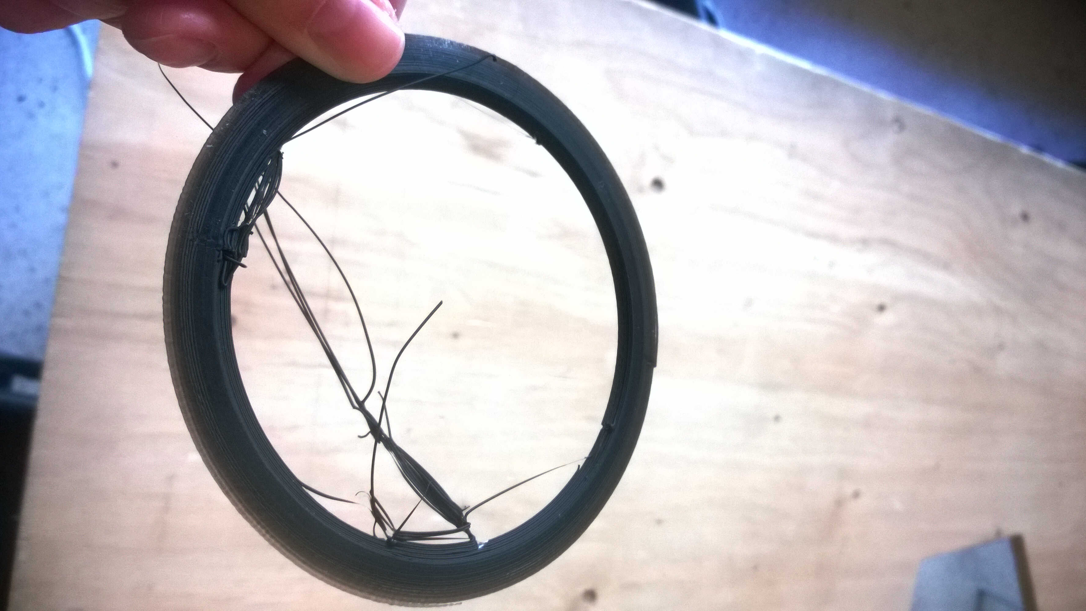
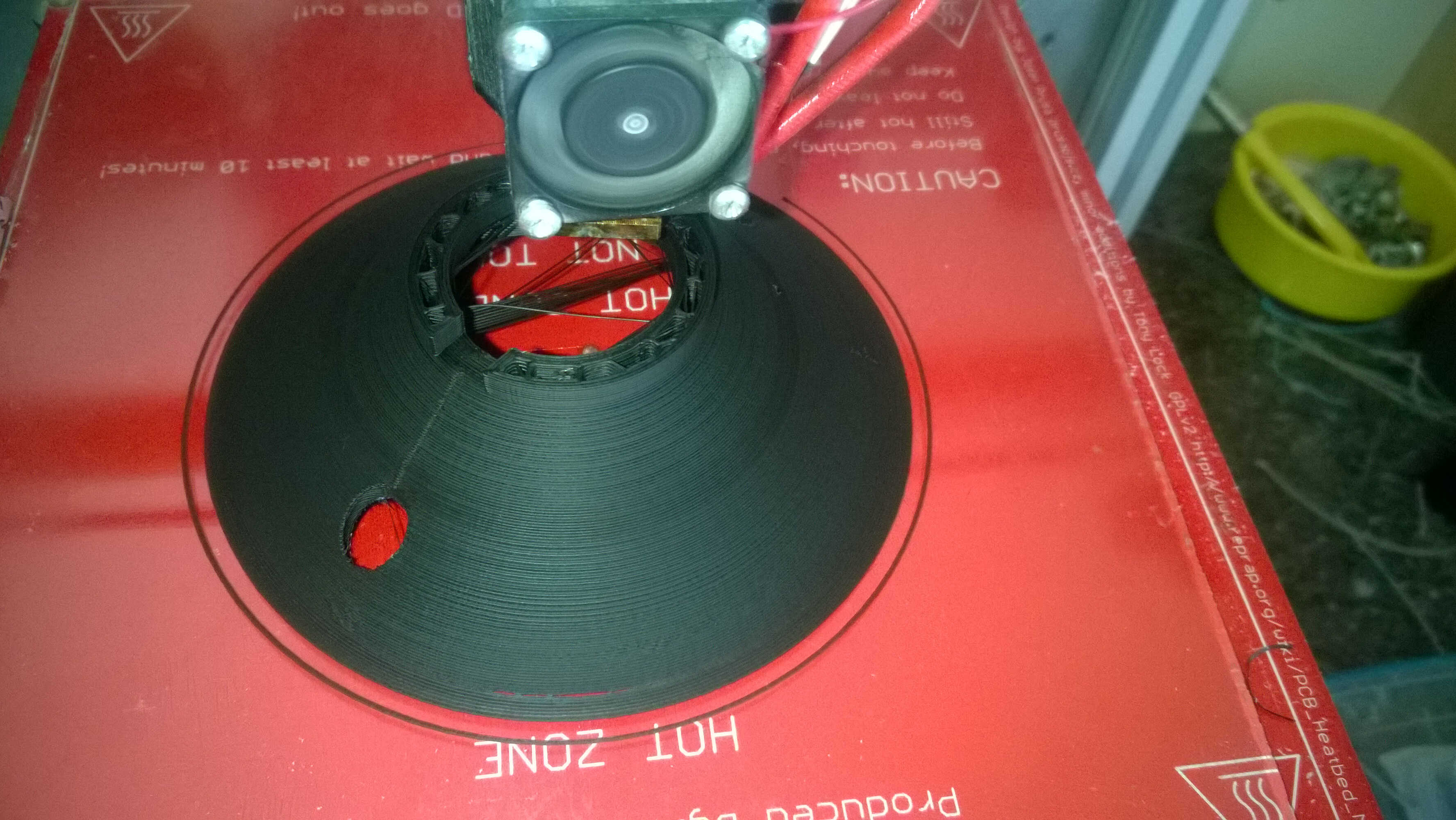
Once the Voronoi mesh generated, the model was introduced in Slic3r. The computation was sluggish. I made sure the deposition was multilayered. The gcode was then transfered to Pronterface. The loading took some time. I launched the printing with the speed at 50%.
printing start
I had to stop almost instantaneously as filament webs were forming and some pillars didn't stick to the bethe d (back).
On the left side of the we can see pillar forming.
Multiple parameters can cause this: extruder temperature, retraction distance, retraction speed...
In order to relaunch with different parameters I had to regenerate a gcode.
Multiple computer crashs made me momentaneously give up.
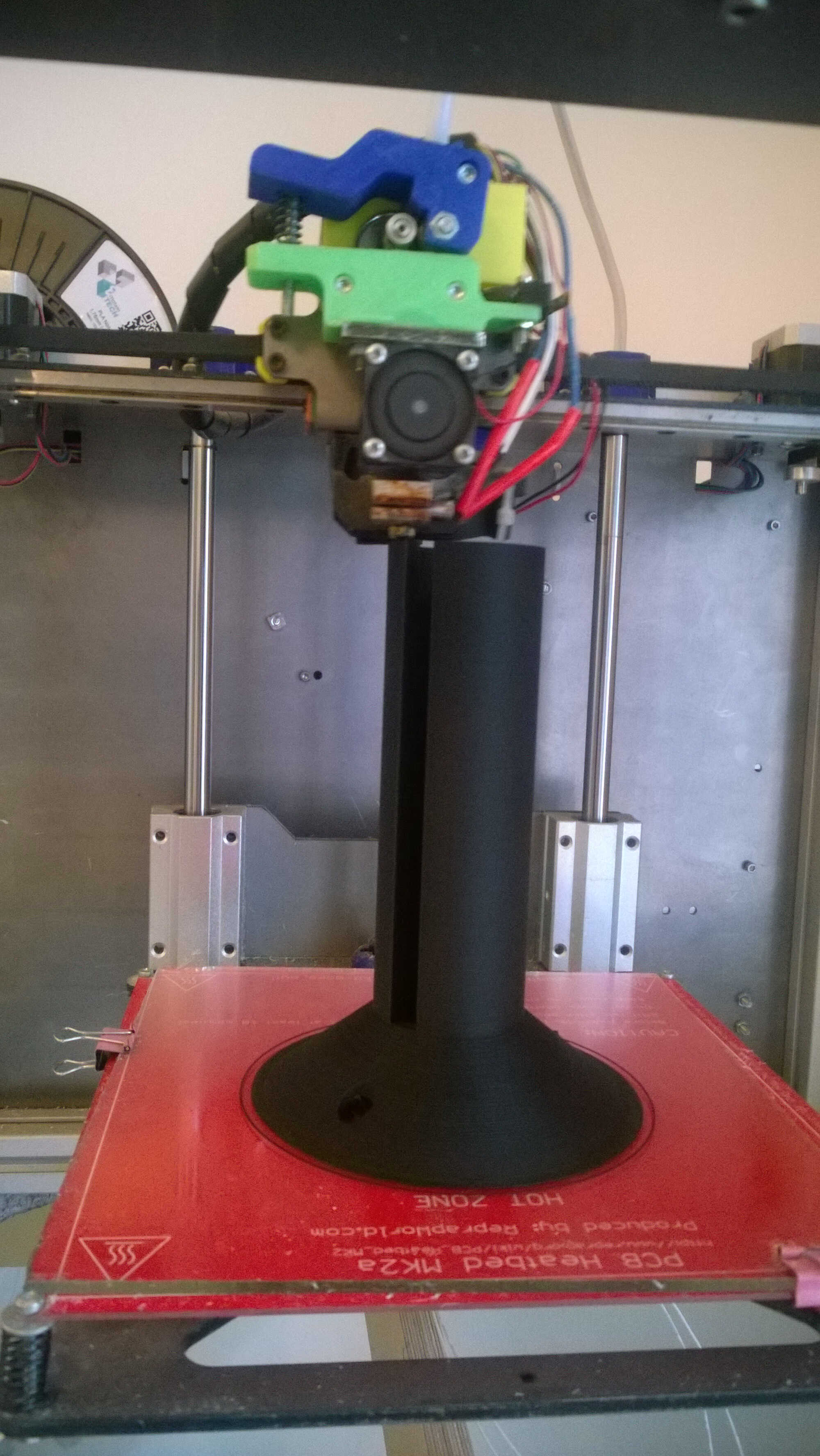
I decided to print the solid version of the scanning. It took quite a while, It was regrettable that I did not print the hollowed version.
printing start
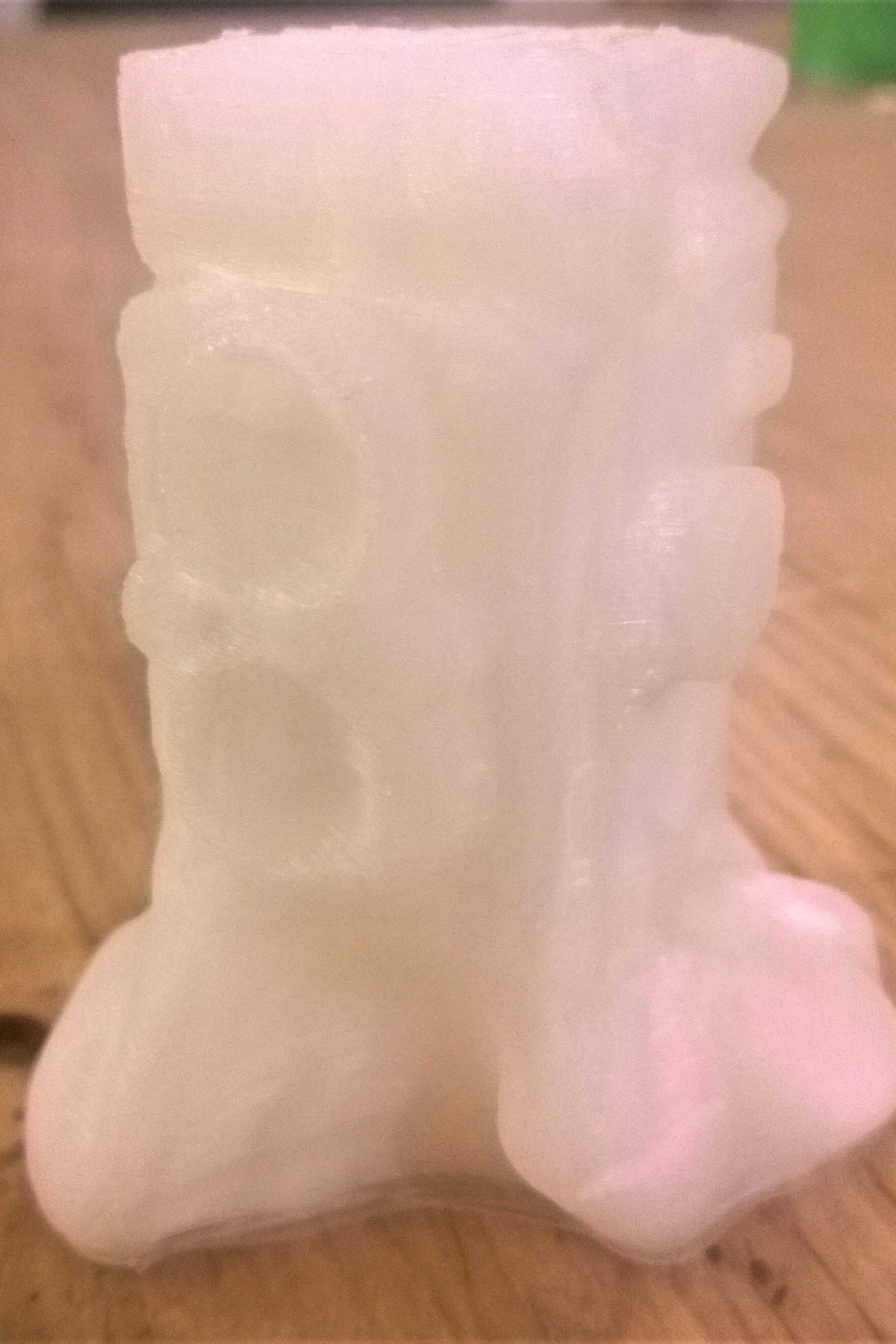
final
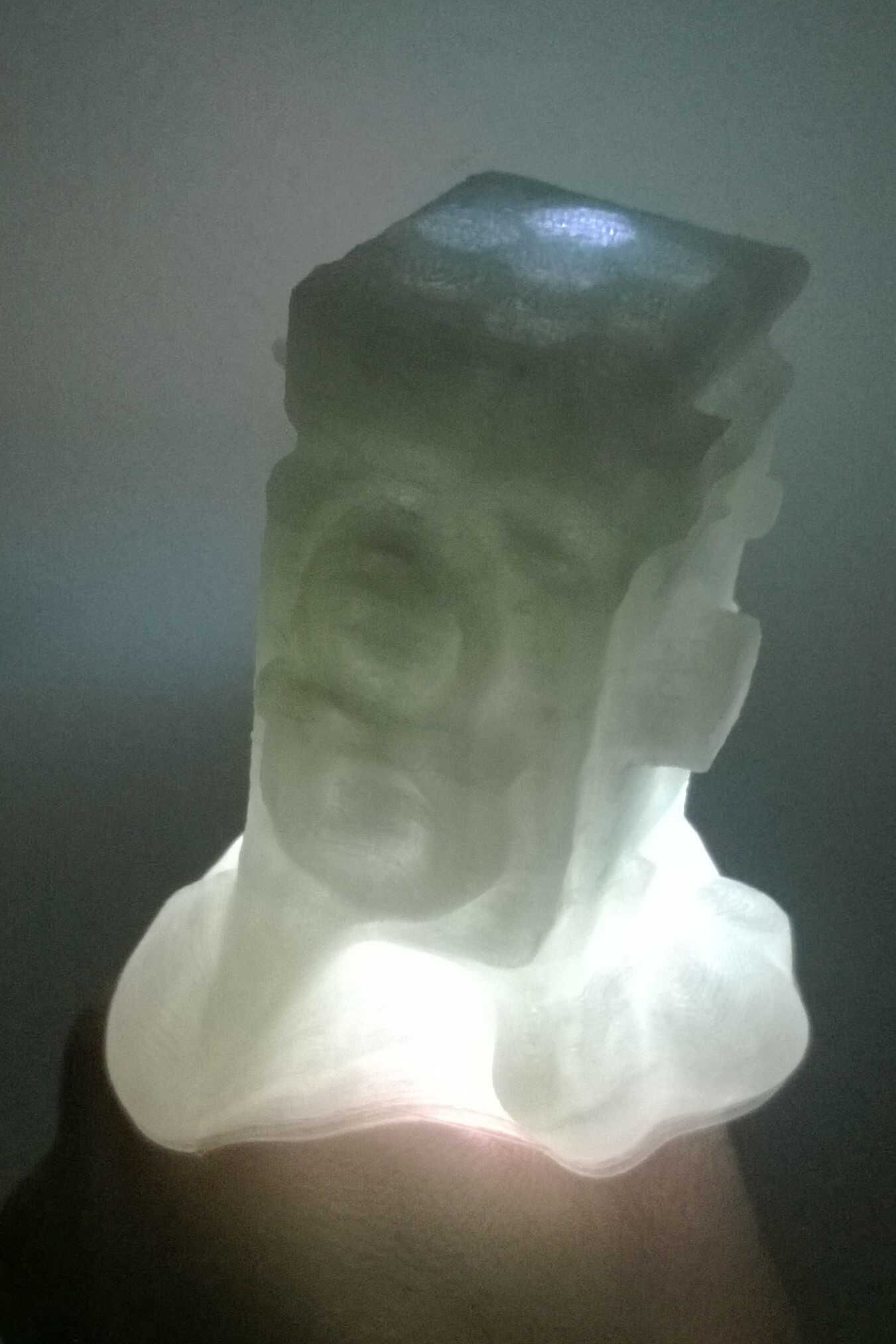
enlighted final
Additional piece
I was told this might not be enough for this assignement. This is why I add a piece I made for the group prject.
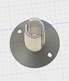
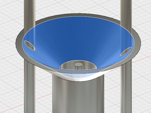
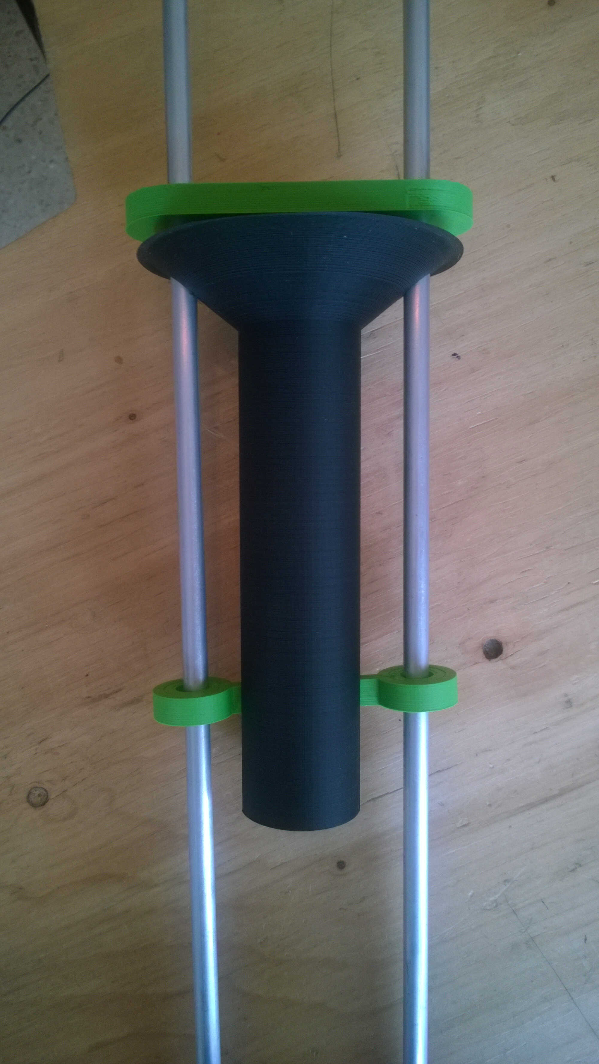
This piece was designed to allow the descent of a specific mobile part along the shaft -hence the tow holes for the 2 shafts- and to prevent the marbles it was supporting to fall. This piece was designed so that the descending part remained parallel and didn't spin. Hence the vertical rails. The upper part is flared in order to collect the marbles. I think this part couldn't be designed with any other technique we saw as it is thin hollow, unsymetrical and long.
piece from above
piece from below
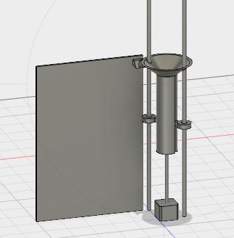
context
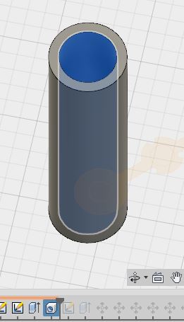
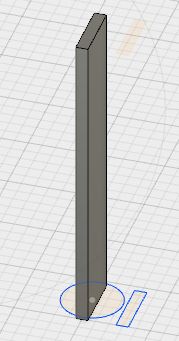
1. I designed a circle that I extruded to the height wished
2. I hollowed it with the Hole tool
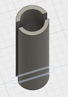
3. I cut it with a "wall" to create the slot with the Combine > Cut tool
I had my main piece
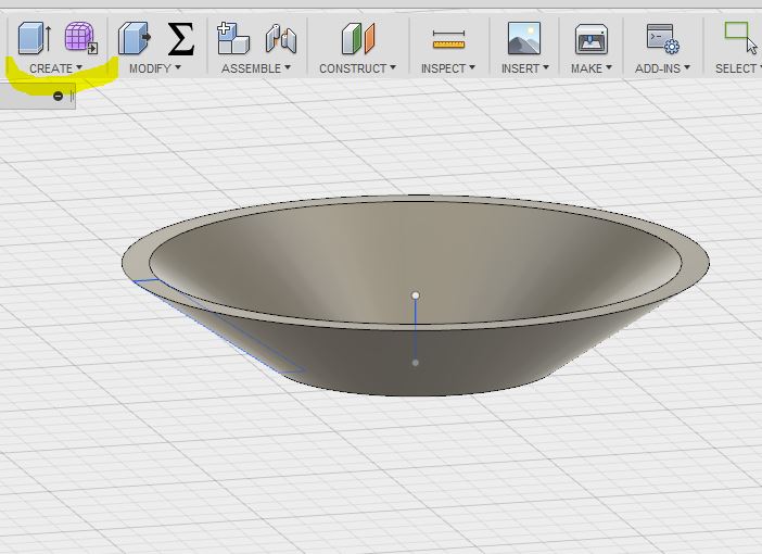
4. I sketched the profile of my funnel
5. I revolved it with the Revolve tool
I had my funnel (which I redrew when realizing my angle was too steep and my walls too thin)
6. I aligned those 2 pieces with my previous ones (the mobile one, the shafts, even the marbles) with the Move tool. I am pretty sure it exist an alignement tool sadly I did not know where.
7. I cut my funnel with the shaft with the Combine Cut tool (I took care to keep the tools)
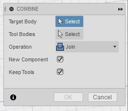
8. I then combined the funnel and the vertical piece into a component with the Combine Tool
9. I had then a body I could export as stl
hollowing
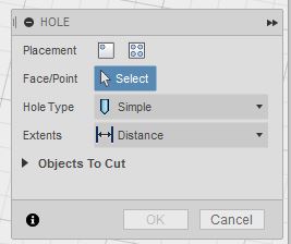
hole tool
extrusion
slot tool
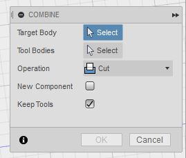
combine to cut
revolution, in blue the original sketch and axis used
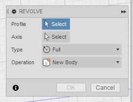
revolution tool
cutting with shafts
component building
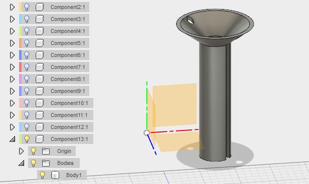
component
funnel angle evolution
export in stl
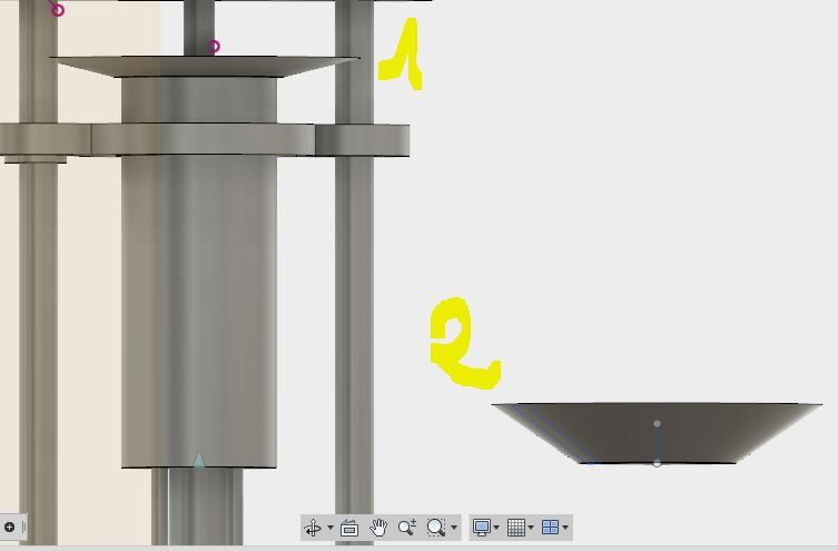
I printed this piece overnight. I had to make several tries as at first my walls were to thin and my upper part angle was too wide. I could print the whole piece but never got a smooth finish of the upper part as the filament seemed to detach. To use this piece I cut the rebel filaments with a cutter.
too thin
correction
almost
I combined my different piece and this one fullfilled its purpose.
with shaft
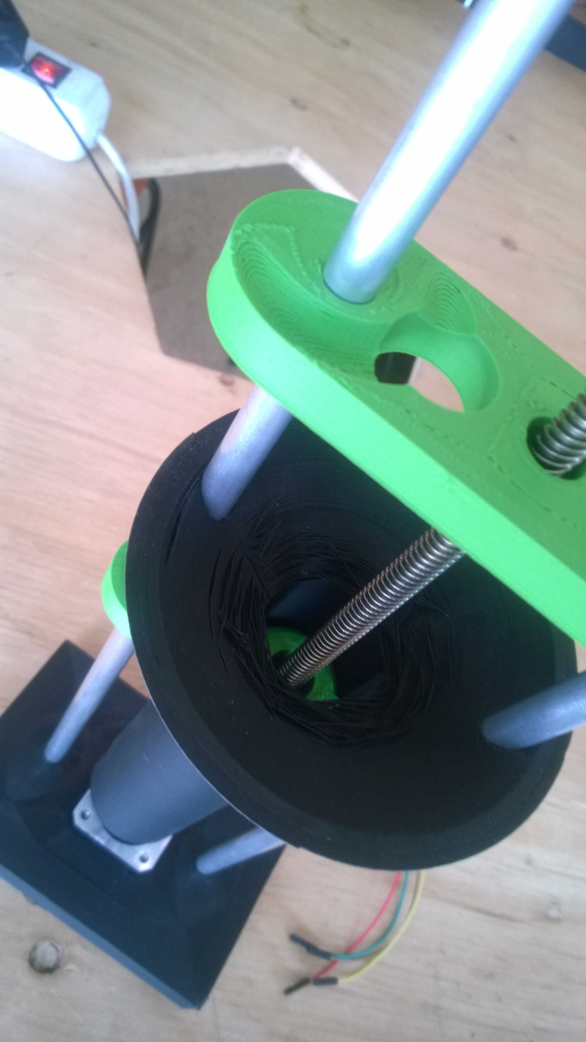
imperfection
Feedback on my work
Insert links between the different tabs to make the website less confusing.
Redesign a final assignement (not based on scanning).
Inspiration
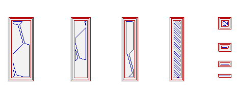
Test fillings/walls
Test to spiralize outer contours
Test dimension discrepancy (with press-fit test for example)
Test overhangs with christmas trees design
Test support need vs. speed