Setup
| Softwares | Fonction |
|---|---|
| Gimp | 2D Image manipulation |
| Inkscape | 2D Vector graphic |
| Rhinoceros | 3D CAD |
| Solidworks | 3D CAD |
| Autodesk Fusion 360 | 3D CAD |
| Grasshopper | Algorithmic 3D CAD |
| Anemona | Grasshopper Loop Plugin |
Skills acquired
Asssesment validation
I tested 4 different 3D CAD softwares. In chronological order: Rhino, Solidworks, Autodesk Fusion 360 and Blockscad3D .
The last one is more of an introduction to CAD. It mimicks a puzzle, where the pieces represent logical statements.
The 3 other have a lot in common.
Rhino is more design/architecture-oriented, and its Grasshopper pluggin allows algorithmic modeling.
Solidworks-a Dassault Systemes software- and Fusion 360 are more engineering-oriented.
Hence the design created with those 2 solutions can be submitted to multiple tests and translated into 2D plans.
Pros and cons identified so far:
Rhino has a dynamic help window, which describes the action you are doing, making very explicite what your nextstep should be.
The online tutorials are making it possible in an hour time to build a nice looking object-they even try to make it humoristic.
I recommand the one about a bottle . Rhino plugin Grasshopper adds to it the possibility to block program.
It's a very powerful addition especially when building repetitive structures or when playing with dimensions.
Solidworks, as said is more engineering-oriented. One big flaw is the memory space it requires to work.
It can be linked to suite softs: FloXpress (Flow resistance simulation) or SimulationXpress (constraints simulation).
Autodesk Fusion 360 is also engineering-oriented and the UX is quite nice.
Its models can be animated,directly printed from a 3D printer, constraints simulated and industrialization anticipated.
While sketching popups appear at the right of the main window listing the action required for the command to work.
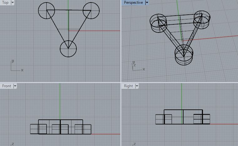
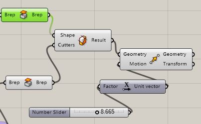
Geometry definition
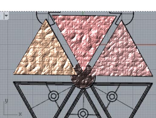
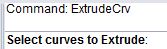
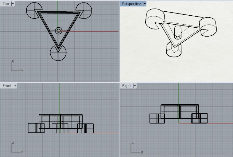
The main forms are extruded from curves.
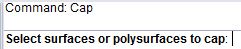
Volume creation
The surfaces are closed by caps.
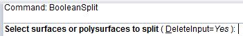
Volume interaction
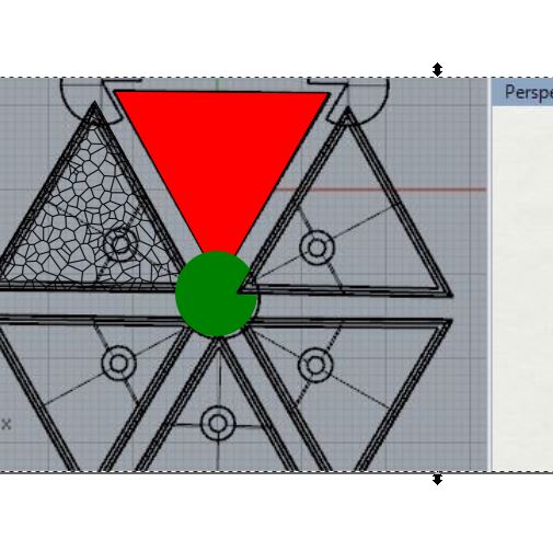
The triangular volume is translated along the Z axis (drag/drop).
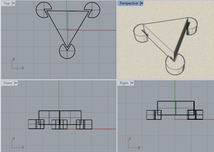
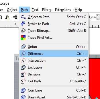
A Boolean split is operated between the cylinders and the triangular volume
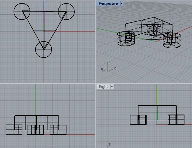
The intersection part was removed and the cylinders slightly moved to make the effect of the split more visible.
Details
The central piece was made empty, in order to install electronics there in the future.
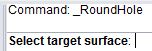
Also a hole was pierced to enable air/water flows and the edges of the superior face were slightly fidgetted (r=0.5).

Replication
To represent a floor covered with the energy harvesting module the mirror tool was used.
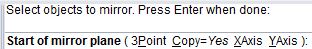
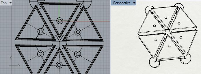
It is to be noted that the mirror doesn't reproduce the splits. Also splitting afterwards won't produce the same results. Now that the central piece has been emptied the cut will be different.
Grasshopper with its block programmation allows the user to visualize the history of creation.
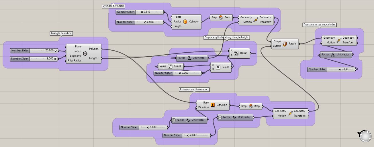
I tried to redo what the same object I built with Rhino.
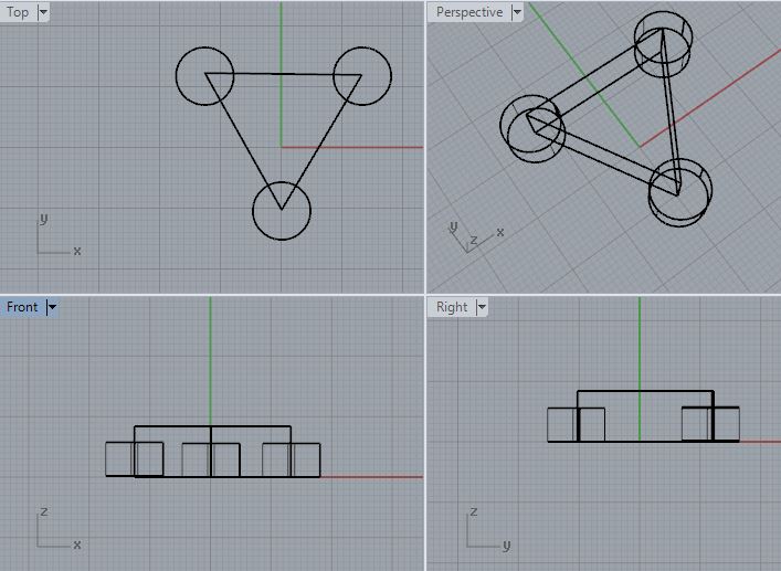
Volume creation
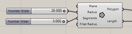
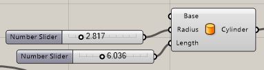
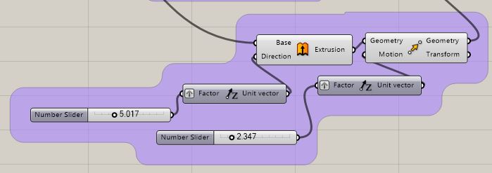
I created a cylinder and extruded a triangle. Both were centered on the origin.
I shifted the triangular volume along the z axis.
Then I wanted to find a mathematical way to shift the cylinder to one pit of the triangular piece.
 I noticed the origin was at the orthocenter of the triangular piece.
The orthocenter is at two third of the height from the pit.
I then capped both surfaces and cut the cylinder with the polygon.
I displaced the cutted part along the x axis to better view the cutting.
I noticed the origin was at the orthocenter of the triangular piece.
The orthocenter is at two third of the height from the pit.
I then capped both surfaces and cut the cylinder with the polygon.
I displaced the cutted part along the x axis to better view the cutting.
Visualization in Rhino
At the same time as the command are entered in Grasshopper working space, the computed results appear in Rhino.
It enables continous checkings.
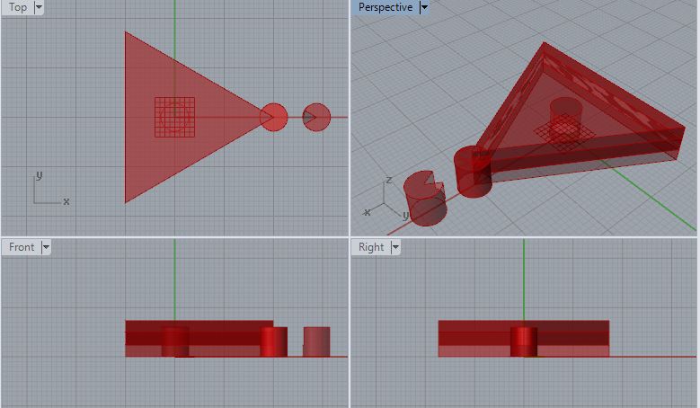
It should be noted that in Rhino's case the cylinder was cut before the central piece shifted upwards.
The shapes before transformation are still visible. Is there a way to remediate to this?
In order to recreate the Rhino object cylinders should be added on the 2 others pits.
Is there an easy way to do it? A command to identify the pits coordonates?
Source file to load here
Gimp
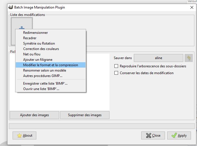
Compression
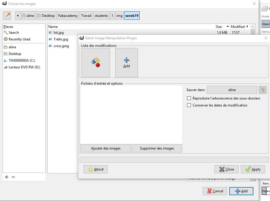
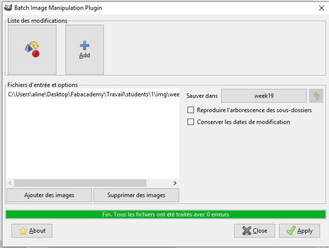
I mainly uses Gimp to resize images. This can be done in batch with Batch Image Manipulation Once in the pluggin select the type of image modification you want -I mainly picked 50% format/compression. Then the file where to store the result and finally the image/folder to compress.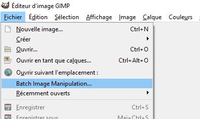
Adjustement
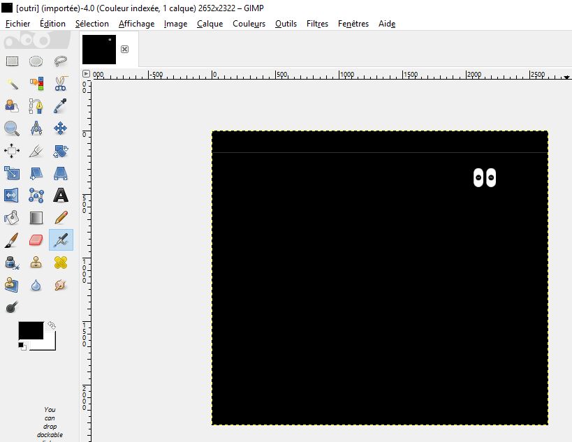
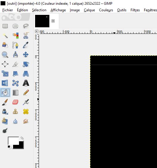
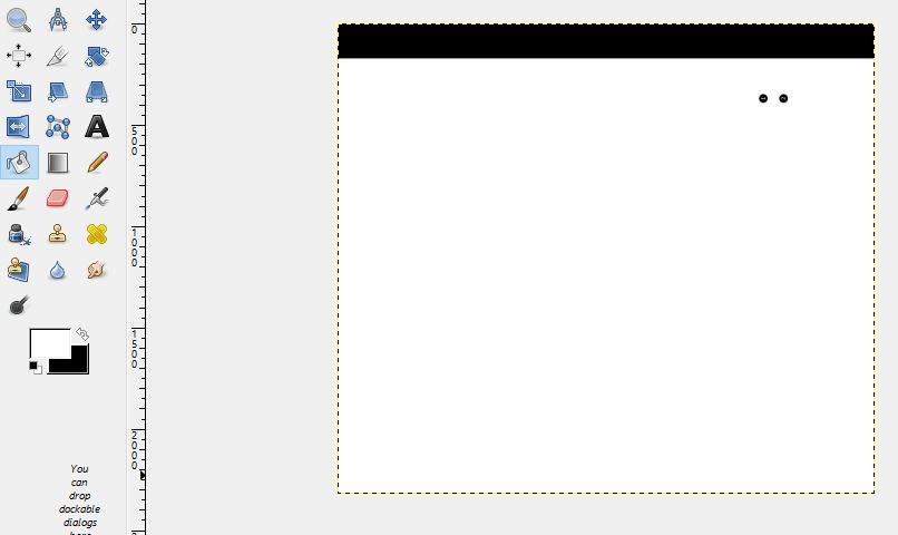
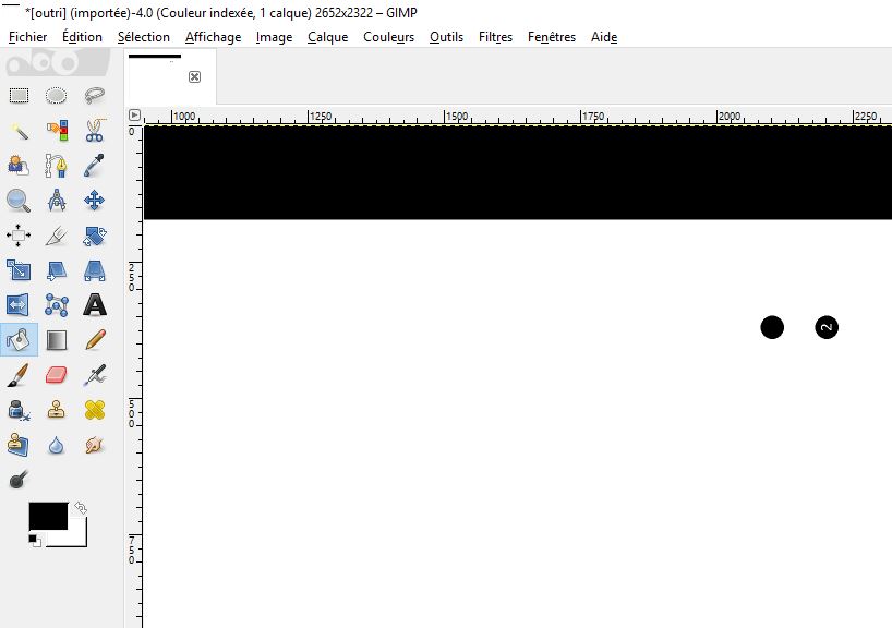
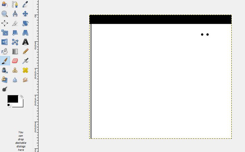
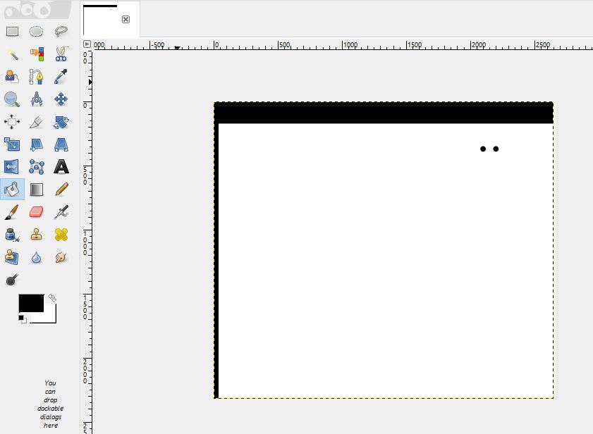
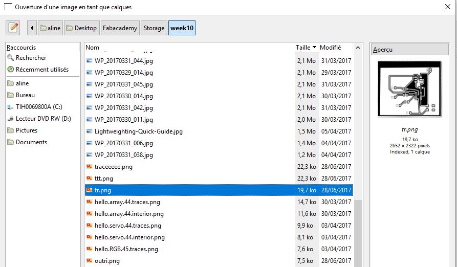
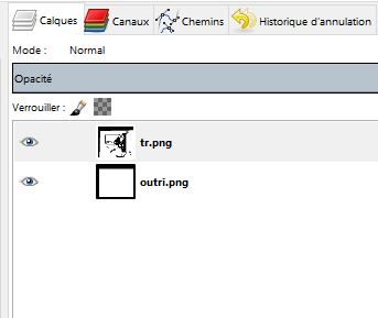
I also use Gimp to adjust circuit board images. I inverse the colours for the outline. The do so I use the Filling tool. I also remove the number with this tool. If the contour is not clearly defined fabmodule won't recognize it so I use the Pencil tool to recreate one in association with the Filling tool. To check if the new contour doesn't cross traces the trace image can be uploaded as layer.
Inkscape
Inkscape is a nice vector drawing tool. I used it when I taught cartography, it makes it really easy to pick a drawing. I did this with a capture from a CAD software. I do the picking with the Bezier tool. Once the contour is closed it is possible to fill the form thanks to the palette at the bottom. They are nice extensions to Inkscape, for example the Voronoi one. It allows to test the rendering of such structure for example before going 3D.
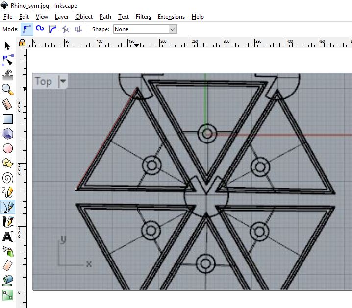
picking
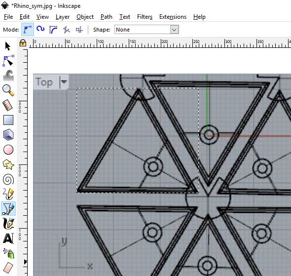
closed
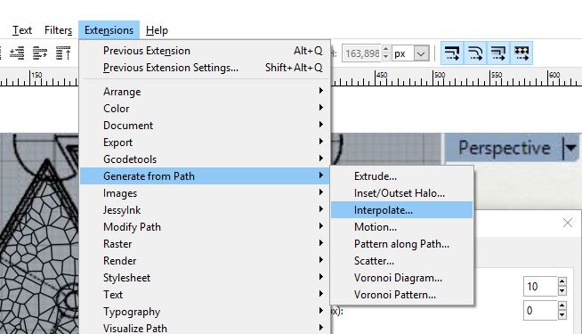
Voronoi extension
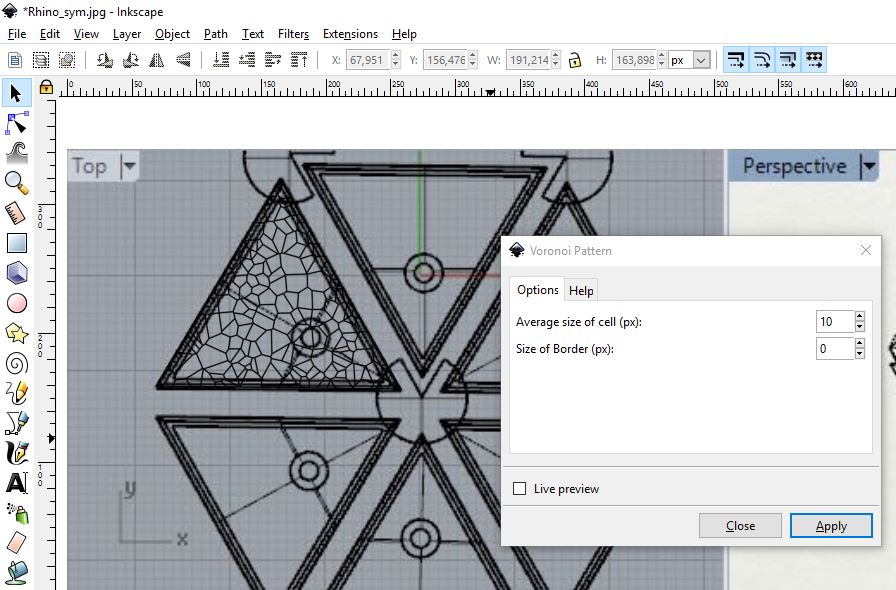
Voronoi
tool

layers
result
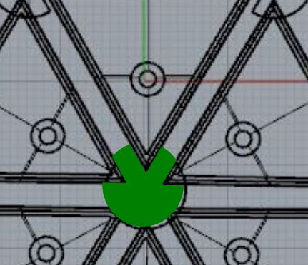
center piece