Abstract
This week was about building an interface linked to previously build input/output.
Some of the question raised were:
- What is a GUI?
- What communication protocol for which interface?
I used several workflows:
Arduino IDE > Processing
Arduino IDE > Python IDLE
My biggest achievement:
My biggest struggle:: Python Tkinter interfacing
Missing material
Chronology
| Thursday | Friday | Monday | Tuesday | |
|---|---|---|---|---|
| Demo | Input interfacing | Documentation | Output interfacing | |
Setup
| Softwares | Fonction |
|---|---|
| Processing 3 | Software for visual arts |
| ControlP5 | a GUI library for Processing |
| Tkinter | Python interface |
Skills acquired
Asssesment validation
Installation
Thomas advised us to start with downloading Processing3 and controlP5 as Arduino and Processing are based on the same principles, they are designed to interact. It is simple to implement serial communication between both as they both have serial libraries. ControlP5 helps building quick modulable interfaces, this is a GUI library. A GUI stands for graphical user interface, this concept was at the base of Apple as mentionned in this website.
  Stands for "Graphical User Interface" and is pronounced "gooey."
  It is a user interface that includes graphical elements, such as windows, icons and buttons.
   The term was created in the 1970s to distinguish graphical interfaces from text-based ones, such as command line interfaces.
   However, today nearly all digital interfaces are GUIs.
The first commercially available GUI, called "PARC," was developed by Xerox.
It was used by the Xerox 8010 Information System, which was released in 1981. After Steve Jobs saw the interface during a tour at Xerox, he had his team at Apple develop an operating system with a similar design.
Apple's GUI-based OS was included with the Macintosh, which was released in 1984.
Microsoft released their first GUI-based OS, Windows 1.0, in 1985.
For several decades, GUIs were controlled exclusively by a mouse and a keyboard.
 While these types of input devices are sufficient for desktop computers, they do not work as well for mobile devices, such as smartphones and tablets. Therefore, mobile operating systems are designed to use a touchscreen interface. Many mobile devices can now be controlled by spoken commands as well.
Because there are now many types of digital devices available, GUIs must be designed for the appropriate type of input.
For example, a desktop operating system, such as OS X, includes a menu bar and windows with small icons that can be easily navigated using a mouse. A mobile OS, like iOS, includes larger icons and supports touch commands like swiping and pinching to zoom in or zoom out. Automotive interfaces are often designed to be controlled with knobs and buttons, and TV interfaces are built to work with a remote control. Regardless of the type of input, each of these interfaces are considered GUIs since they include graphical elements.
NOTE: Specialized GUIs that operate using speech recognition and motion detection are called natural user interfaces, or NUIs.
ControlP5 project is very well documented in this website and comes with a lot of examples. As its name indicates, ControlP5 is related to input control.
First try
I first wanted to use Processing to visualize inputs. I found OpenProcessing website very inspiring and very soothing. All the art potential of Processing is illustrated on this website. I dreamed of having an input used to generate an animation. Files are all open-source.
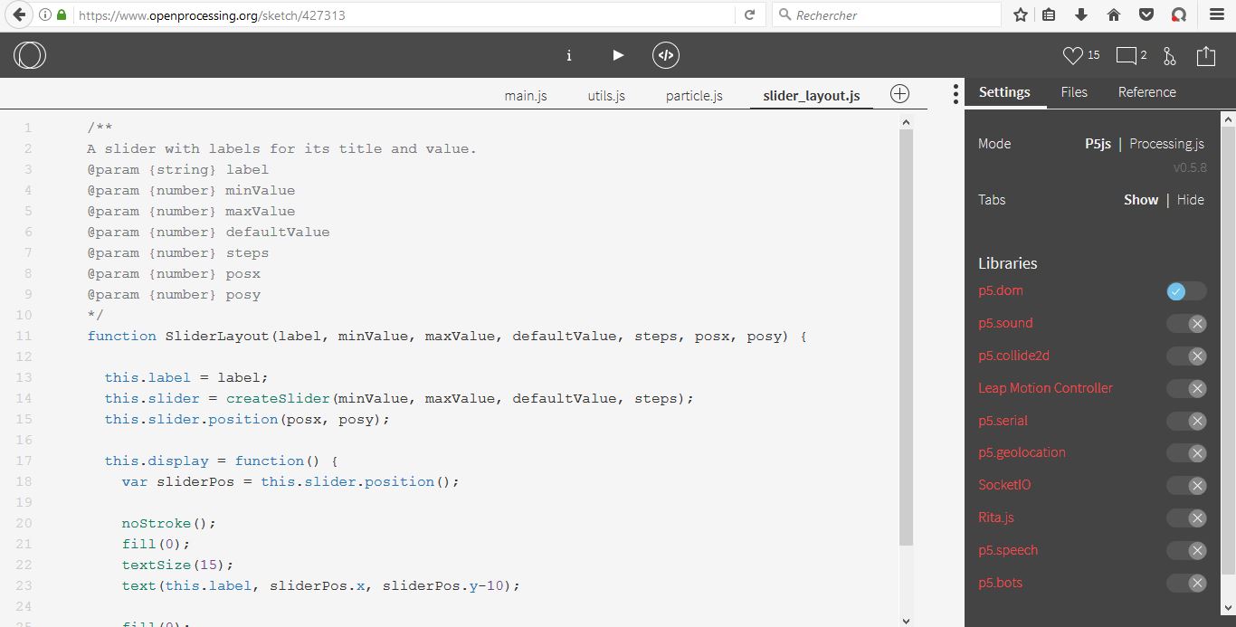
Openprocessing source files
Yassine warned me, the openprocessing sketch are at disposal but they can't be directly used in Processing because of their fomat (.js I believe). This can apparently be circumvent by adding the p5.js Mode library in Processing -available in the library selection accessible from Processing. So I created the simplest representation of a single input: a progress bar. I did so by superposing 2 rectangles, one having its width function of the input value. As input I used an accelerometer connected to my Arduino in I2C(6 wire connexion SDA/SCL/GND/VCC/SDO/CS -A4/A5/13 from the Arduino side). I saw the connexion scheme but this puzzles me as there are SDA/SCL pins on Arduino Uno.
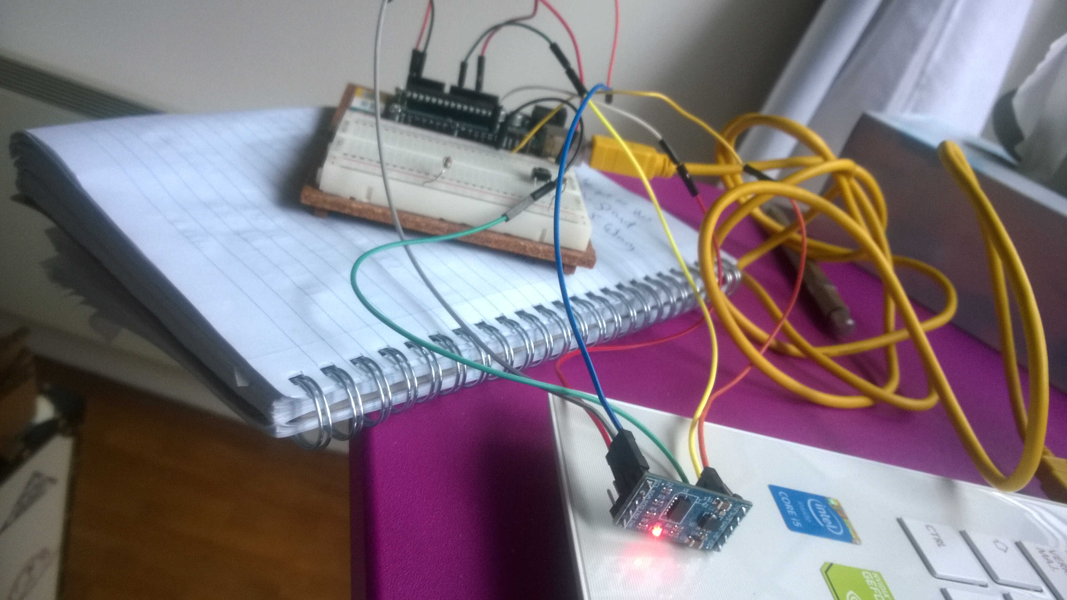
Arduino wiring
The rendering is the following:
The Processing code is:
  import processing.serial.*;
  Serial port;
  float roll;

  void setup(){
    size(440, 220);
    String arduinoPort = Serial.list()[0];
    port = new Serial(this, arduinoPort, 9600);
  }
  void draw(){if (port.available()>0){
    roll = port.read();
  }

  print(roll);
  background(240);
  rect(40, 60, 255, 50);
  fill(150);
  rect(40, 60, roll, 50);
  fill(244,66,66);

  }
}
The rendering was not perfect at the first try. First I didn't modify the Arduino code which was outputting several numbers with texts. I reduced the serial.prints to 1 value, the roll value. Also Processing kept reading the value 10. This is due to Arduino's code which contains Serial.Write(10). I first tried to delete this line but I is needed for I2C communication of the accelerometer. I could circumvent this by creating a condition. I added a delay for the reading to smooth the reading.
Arduino
      #include <Wire.h>

      #define DEVICE (0x53)      //ADXL345 device address
      #define TO_READ (6)        //num of bytes we are going to read each time (two bytes for each axis)

      byte buff[TO_READ] ;        //6 bytes buffer for saving data read from the device
      char str[512];              //string buffer to transform data before sending it to the serial port
      int regAddress = 0x32;      //first axis-acceleration-data register on the ADXL345
      int x, y, z;                        //three axis acceleration data
      double roll = 0.00, pitch = 0.00;       //Roll & Pitch are the angles which rotate by the axis X and y
      //in the sequence of R(x-y-z),more info visit
      // https://www.dfrobot.com/wiki/index.php?title=How_to_Use_a_Three-Axis_Accelerometer_for_Tilt_Sensing#Introduction

      void setup() {
        Wire.begin();         // join i2c bus (address optional for master)
        Serial.begin(9600);  // start serial for output

        //Turning on the ADXL345
        writeTo(DEVICE, 0x2D, 0);
        writeTo(DEVICE, 0x2D, 16);
        writeTo(DEVICE, 0x2D, 8);
      }

      void loop() {

        readFrom(DEVICE, regAddress, TO_READ, buff); //read the acceleration data from the ADXL345
                                                    //each axis reading comes in 10 bit resolution, ie 2 bytes.  Least Significat Byte first!!
                                                    //thus we are converting both bytes in to one int
        x = (((int)buff[1]) << 8) | buff[0];
        y = (((int)buff[3])<< 8) | buff[2];
        z = (((int)buff[5]) << 8) | buff[4];

        //we send the x y z values as a string to the serial port
        //Serial.print("The acceleration info of x, y, z are:");
        //sprintf(str, "%d %d %d", x, y, z);
        //Serial.print(str);
        Serial.write(10);
        //Roll & Pitch calculate
        RP_calculate();
        //Serial.print("Roll:");
        Serial.print( roll );
        //Serial.print("Pitch:"); Serial.println( pitch );
        //Serial.println("");
        //It appears that delay is needed in order not to clog the port
        delay(500);
      }

      //---------------- Functions
      //Writes val to address register on device
      void writeTo(int device, byte address, byte val) {
        Wire.beginTransmission(device); //start transmission to device
        Wire.write(address);        // send register address
        Wire.write(val);        // send value to write
        Wire.endTransmission(); //end transmission
      }

      //reads num bytes starting from address register on device in to buff array
      void readFrom(int device, byte address, int num, byte buff[]) {
        Wire.beginTransmission(device); //start transmission to device
        Wire.write(address);        //sends address to read from
        Wire.endTransmission(); //end transmission

          Wire.beginTransmission(device); //start transmission to device
        Wire.requestFrom(device, num);    // request 6 bytes from device

        int i = 0;
        while(Wire.available())    //device may send less than requested (abnormal)
        {
          buff[i] = Wire.read(); // receive a byte
          i++;
        }
        Wire.endTransmission(); //end transmission
      }

      //calculate the Roll&Pitch
      void RP_calculate(){
        double x_Buff = float(x);
        double y_Buff = float(y);
        double z_Buff = float(z);
        roll = atan2(y_Buff , z_Buff) * 57.3;
        pitch = atan2((- x_Buff) , sqrt(y_Buff * y_Buff + z_Buff * z_Buff)) * 57.3;
      }
Second try
Roll describes the angular movement around the x axis so instead of a progress bar a rotating bar would be more intuitive. I modified the plotting to:
  {if (roll!=10)
 background(240);
 rectMode(CENTER);
 translate(width/2, height/2);
 rotate(radians(roll));
 rect(0, 0, 150, 50);
 fill(150);
}
I could notice that the value received by the Arduino serial monitor are not the same as the one received by Processing. If Arduino responded promptly to a change of angle, Processing seemed to be stuck in the [46-60] range.
Arduino serial:
Processing serial:
The if condition worked for the display on the monitor but not for the plot-the plot circumvent the if.
Commercial GUI
Last week I talked about LittleBits Cloudbit. Cloudbit comes with its interface. This is a basic one. For example cursor to change the output intensity:
In ESP8266 library were some examples, among them a crib sensor. The sketch was connected to IFTTT and to Blynk. Blynk is a GUI app for Arduino/Raspberry projects. I wish I could test it but I have got a Windows phone and its "only" working with iPhones and Android phones.
ESP to Processing
I then tried to use the ESP8266 as master of the accelerometer. This is done thanks to a 4 wire connexion (SDA/SCL/VCC/GND).
Installation
At input week I did a thorough înstall to enable Neil's Python, so I installed numpy, cython, checked Tkinter.... But I have 2 versions of Python on my computer 2.7 (for gestalt originally) and the 3.6.
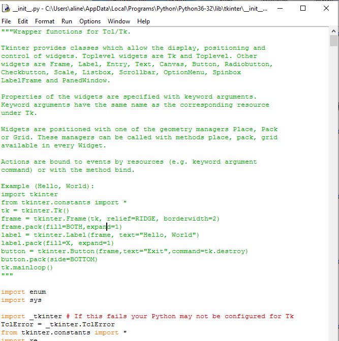
When I ran Neil's python no interface was displayed. I tried to import Tkinter and call the test Tkinter function.
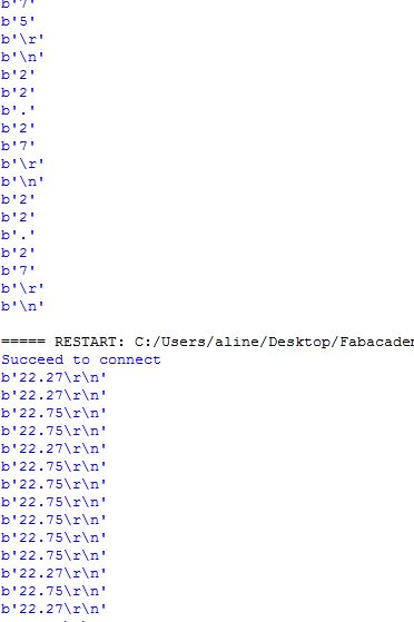
I succeeded in running the code with Python 3.6 even if it struggles to recognize Tkinter (it needs to be imported at every use) but the 2.7 version couldn't get connected to the port. I went on with Python 3.6 I noticed a format issue, on Python shell monitor I read "b value \r \n". I learned this is the UTF-8 encoding. I wondered if it was realted to my use of readline() instead of read(). It turned out not to be.
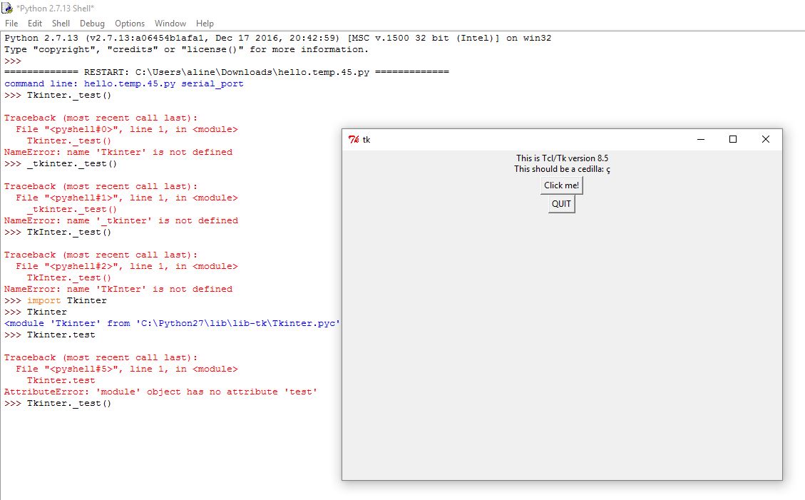
Tkinter test function
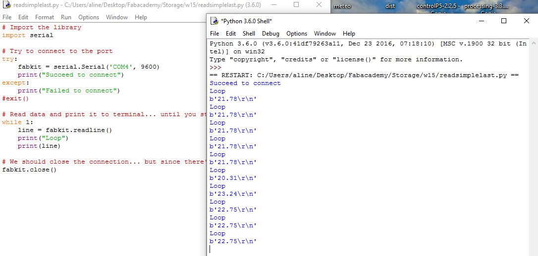
readline() reception on Python 3.6
read() vs. readline()
Tkinter example and inspiration
Finally I was able to run and visualize Neil temperature bargraph even on the 2.7 version.
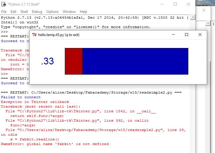
sucessfull display
First try
I then decided create the simpliest code to mimick what I did in Processing.
      # Import the library
import serial

#  check command line arguments
#
if (len(sys.argv) != 2):
   print "command line: hello.temp.45.py serial_port"
   sys.exit()
port = sys.argv[1]
#
# open serial port
#
ser = serial.Serial(port,9600)
ser.setDTR()

# Read data and print it to terminal... until you stop the program
while 1:
    line = ser.readline()
print line

# We should close the connection... but since there's a while 1 loop before, we never reach this
fabkit.close()
Ser.setDTR(); DTR - Data terminal ready is used on the arduino to reset the processor..
Second try
I then added the rectangle plots.
  # Import the library
import serial
from tkinter import *
from tkinter.constants import *

# Try to connect to the port
try:
    fabkit = serial.Serial('COM4', 9600)
    print("Succeed to connect")
except:
    print("Failed to connect")
#exit()

WINDOW = 600 # window size


def idle(parent,canvas):

   while 1:

        x =fabkit.readline()
        print(x)
        #value = x.decode('utf-8')
        #print(value)
        #val=int(value)
        #print(val)
        data = [float(val) for val in x.split()]
        print(data)
        y = int(.2*WINDOW + (.9-.2)*WINDOW*abs(data[0]))
        print(y);
        canvas.itemconfigure("text",text="%.1f"%abs(data[0]))
        canvas.coords('rect1',.2*WINDOW,.05*WINDOW,y,.2*WINDOW)
        canvas.coords('rect2',y,.05*WINDOW,.9*WINDOW,.2*WINDOW)
        canvas.update()
        #parent.after_idle(idle,parent,canvas)

# start plotting
#
root = Tk()
root.title('hello.temp.45.py (q to exit)')
root.bind('q','exit')
canvas = Canvas(root, width=WINDOW, height=.25*WINDOW, background='white')
canvas.create_text(.1*WINDOW,.125*WINDOW,text=".33",font=("Helvetica", 24),tags="text",fill="#0000b0")
canvas.create_rectangle(.2*WINDOW,.05*WINDOW,.3*WINDOW,.2*WINDOW, tags='rect1', fill='#b00000')
canvas.create_rectangle(.3*WINDOW,.05*WINDOW,.9*WINDOW,.2*WINDOW, tags='rect2', fill='#0000b0')
canvas.pack()
root.after(1,idle,root,canvas)
root.mainloop()

# We should close the connection... but since there's a while 1 loop before, we never reach this
fabkit.close()
Final try
  # Import the library
import serial
from tkinter import *
from tkinter.constants import *

# Try to connect to the port
try:
    fabkit = serial.Serial('COM4', 9600)
    print("Succeed to connect")
except:
    print("Failed to connect")
#exit()

WINDOW = 600 # window size


        #parent.after_idle(idle,parent,canvas)

# start plotting
#
root = Tk()
root.title('hello.temp.45.py (q to exit)')
root.bind('q','exit')
canvas = Canvas(root, width=WINDOW, height=.25*WINDOW, background='white')
canvas.create_text(.1*WINDOW,.125*WINDOW,text=".33",font=("Helvetica", 24),tags="text",fill="#0000b0")
canvas.create_rectangle(.2*WINDOW,.05*WINDOW,.3*WINDOW,.2*WINDOW, tags='rect1', fill='#b00000')
canvas.create_rectangle(.3*WINDOW,.05*WINDOW,.9*WINDOW,.2*WINDOW, tags='rect2', fill='#0000b0')
canvas.pack()
while 1:
    x =fabkit.readline()
    print(x)
    data = [float(val) for val in x.split()]
    print(data)
    y = int(.2*WINDOW + (.9-.2)*WINDOW*(data[0])/1023)
    print(y);
    canvas.itemconfigure("text",text="%.1f"%(data[0]))
    canvas.coords('rect1',.2*WINDOW,.05*WINDOW,y,.2*WINDOW)
    canvas.coords('rect2',y,.05*WINDOW,.9*WINDOW,.2*WINDOW)
    canvas.update()
root.mainloop()

# We should close the connection... but since there's a while 1 loop before, we never reach this
fabkit.close()
Now that I tried interfacing input, I would like to test output. I make the CharliePlexing in output week and, as I found its wiring not that straighfroward to understand I would like to create an interface that makes it simpler. To do so ideally I would link Processing to my board -the microcontrollerr is a Attiny 44V. I investigated Firmata, as it is advertised as "a generic protocol for communication with microcontroller from software". Firmata is not the only protocol others exist such as Nanpy.
Firmata
I tested it by loading StandardFirmata on my ArduinoUno and by loading a blink sketch on Processing after loading the Arduino/Firamta library in Processing. I found the indications here. This way the led 13 blink was conditionned to the running of the code, not to the powering of the board as it was the case until now.
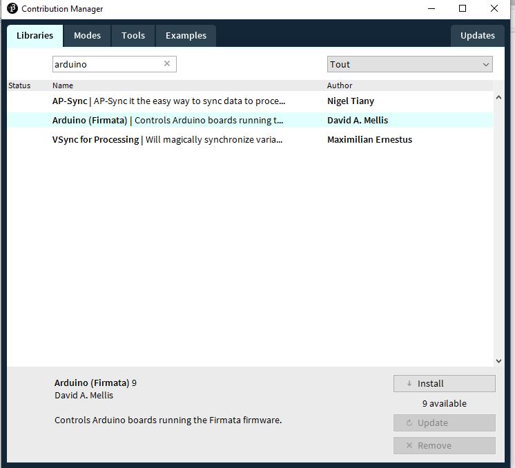
Processing library addition
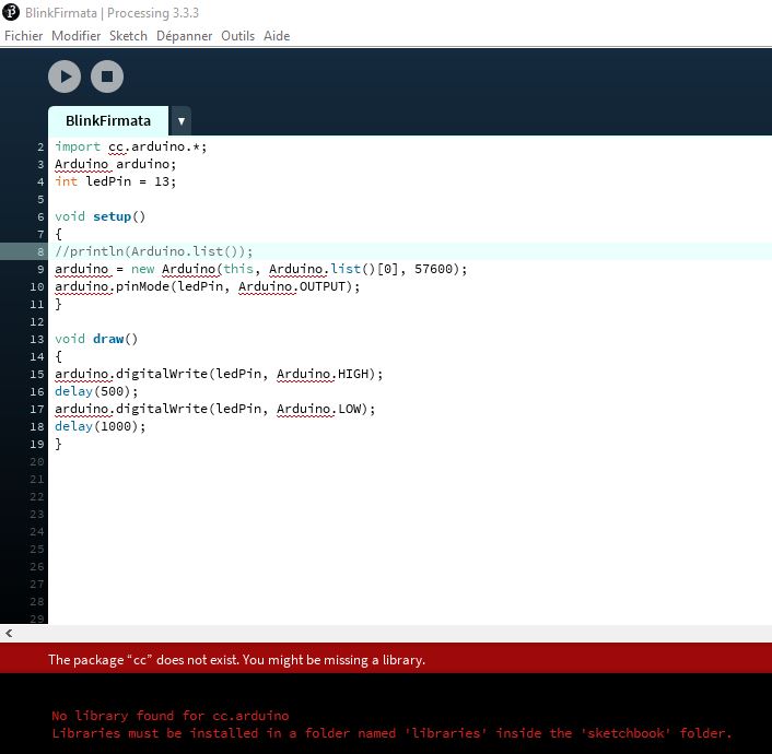
Blink Firmata sketch
Here the Firmata Blink:
I wondered if Firmata sketch could be loaded to Attiny 44. I looked at the sketch, it is quite long so it won't fit as it is in the Attiny memory. I saw section about servos (it is also calling the servo library) so maybe some parts could be removed. I saw mentions to I2C, so it might rely on this protocol. If it is I would need to find a way to implement I2C in ATTiny 44. I read about TinyWire library, this is a first hint. I also saw mentions of Arduino, so I wonder what non-Arduino microcontroller it can handle. I will test Firmata further, using output this time -coupled with a temperature sensor. I might have to load AnalogFirmata on my Arduino board for this. I found out that to deal with analog I/O AnalogFimata/SimpleAnalogFirmata should be loaded to the Arduino/Satshakit.
Events
If I can't use Firmata, maybe I could use events (cf avr/interrupt.h) to control my Attiny and tf the controlling of the Attiny44 ends up being too tricky I would consider outputting the pins combination it is using for the Charlieplexing patterns.
Another hint
I kept looking on the Internet if someone already established a I2C communication between a Arduino and a Attiny44. I found many informations showing that Attiny44 could handle more than I thought for example solenoid motors. I looked at my CharliePlexing board, the Attiny44 pins available through ISP header are PA5(MISO/OC1/PWM/ADC), PA4(ADC4/SCK/SCL) and PA6(PWM/MOSI/SDA). Based on this observation I2C is theoritically possible between a Satchakit and my Charlieplexing board. I finally found a project confirming my intuition. As this wasn't perfectly documented I had to test a lot
TinyWire
In this project the Attiny44 uses a library called TinyWireS. I looked in Arduino IDE libraries list, found TinyWireM and tried to use it.
TinyWireM example
Once loaded the TinyWireM library gives access to examples, the most interresting being Tiny85_Temp. This example really helped me understand how a master can pilot slave. This project operates with a Attiny85 as master and a temperature sensor as slave. The skech unroll as following:
Setup: TinyWireM.begin() then the slave transmission is initiated with:
TinyWireM.beginTransmission(sensor adress)
TinyWireM.send(0xAC)- access command register
TinyWireM.send(B00001)- one shot mode battery saving
TinyWire.endTransmission()
Loop: It provides a nice examples of Led value display with a Led blinking the tens and another one the units The temperature is recovered by an Arduino:
TinyWireM.beginTransmission(sensor adress)
TinyWireM.send(0xEE) -start conversion
TinyWireM.endTransmission() -1 byte is send to slave
Then
TinyWireM.beginTransmission(sensor adress)
TinyWireM.send(0xAA) -read temperature
TinyWireM.endTransmission()
TinyWireM.requestFrom(sensor adress, 1) - request one byte
TinyWireM.receive()-receive the data
To sum up the master first dictates the mode the sensor will be oparating, then ask for a conversion, then to ask a temperature and finally to receive one byte.
Sensor adress can be found in data sheets, Attiny44 adress in 0x26 usually. I saw a nice project of a I2C adress display based on an Attiny44.
Everywhere I read that pull-ups on SDA/SCL are important. I wonder if internal pull-ups also work, in case they don't a trough hole resistor with legs could probably be added to the board.
TinyWireM test
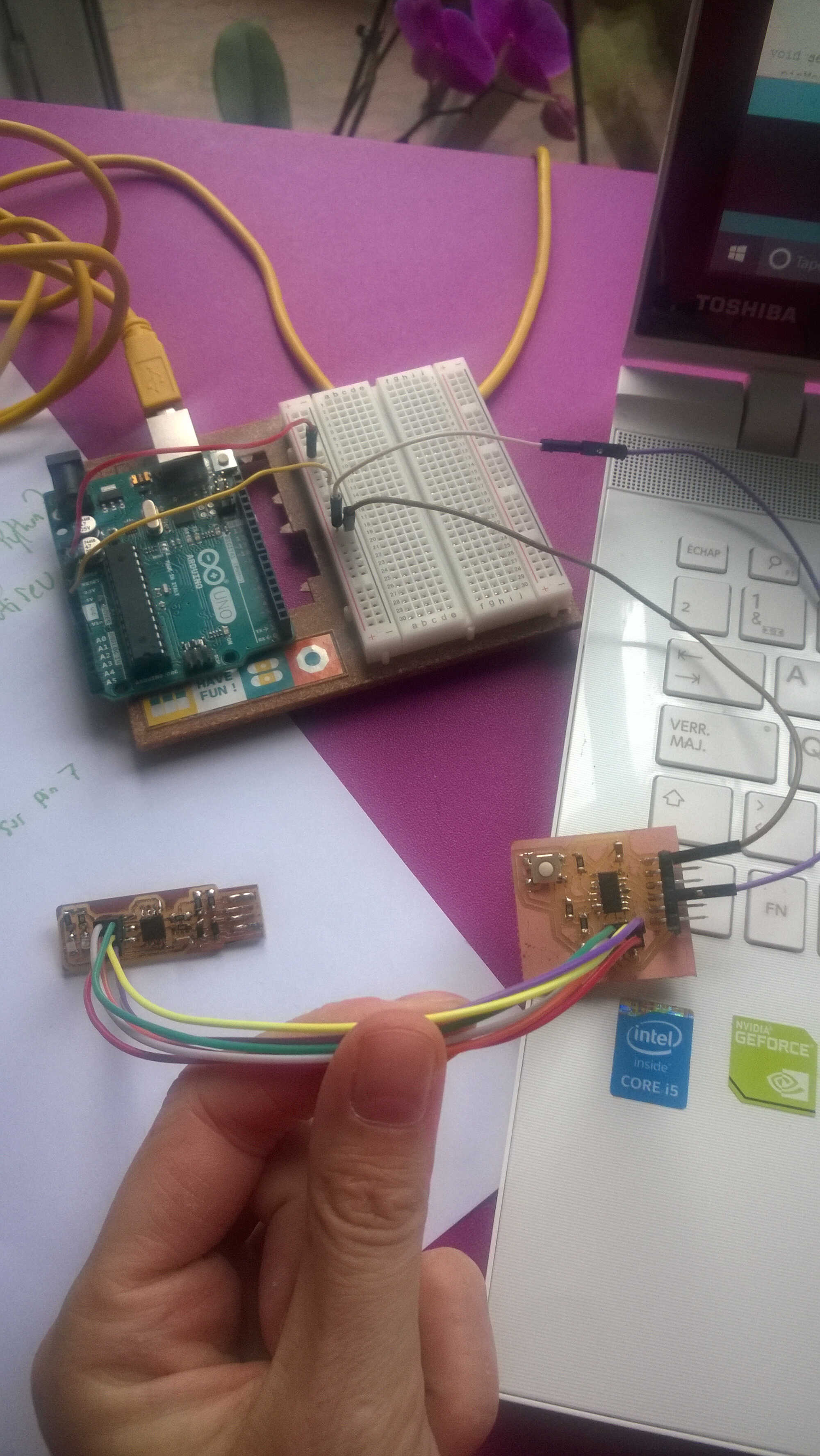
I made a test with the code provided in here but with TinyWireM. Every time the master counter,x, reaches 5 the Attiny44 is supposed to light up.
I loaded the Satchakit master -I noticed this operation is highly sensitive to the wires I use
  #include <Wire.h>

#define LED_PIN 13
byte x = 0;

void setup()
{
  Wire.begin(); // Start I2C Bus as Master
  pinMode(LED_PIN, OUTPUT);
  digitalWrite(LED_PIN, LOW);

}
void loop()
{

  Wire.beginTransmission(0x26); // transmit to device #9
  Wire.write(x);              // sends x
  Wire.endTransmission();    // stop transmitting
  x++;
  if (x > 5) x=0;
  delay(450);
}
I loaded the Attiny 44 with the slave sketch. One difference I noticed was that with TinyWireM the begin function doesn't need an adress as argument. I defined the Pin 0 as the one blinking.
Processing library addition
I am unsure of if I need to define a "ground" pin. This will be tested. Using I2C as protocol is likely to make some Charlieplexing cmbination impossible as it pass through the pin 4 which is related to the second row. The sketch only took 15% of the Attiny memory space.
  #include <TinyWireM.h>   // wrapper class for I2C slave routines
//#include <USI_TWI_Master.h>

//#include "TinyWireM.h"

#define I2C_SLAVE_ADDR  0x26            // i2c slave address (38)
#define LED1_PIN         0
#define LED2_PIN         1

void setup(){
  pinMode(LED1_PIN,OUTPUT);             // for general DEBUG use

  TinyWireM.begin();      // init I2C Slave mode
}


void loop(){
  byte byteRcvd = 0;
  if (TinyWireM.available()){           // got I2C input!
    byteRcvd = TinyWireM.receive();     // get the byte from master

            if(byteRcvd == 5){
              digitalWrite(LED1_PIN,HIGH);
              delay(1000);
            }
            else{
              digitalWrite(LED1_PIN,LOW);
            }
  }
}
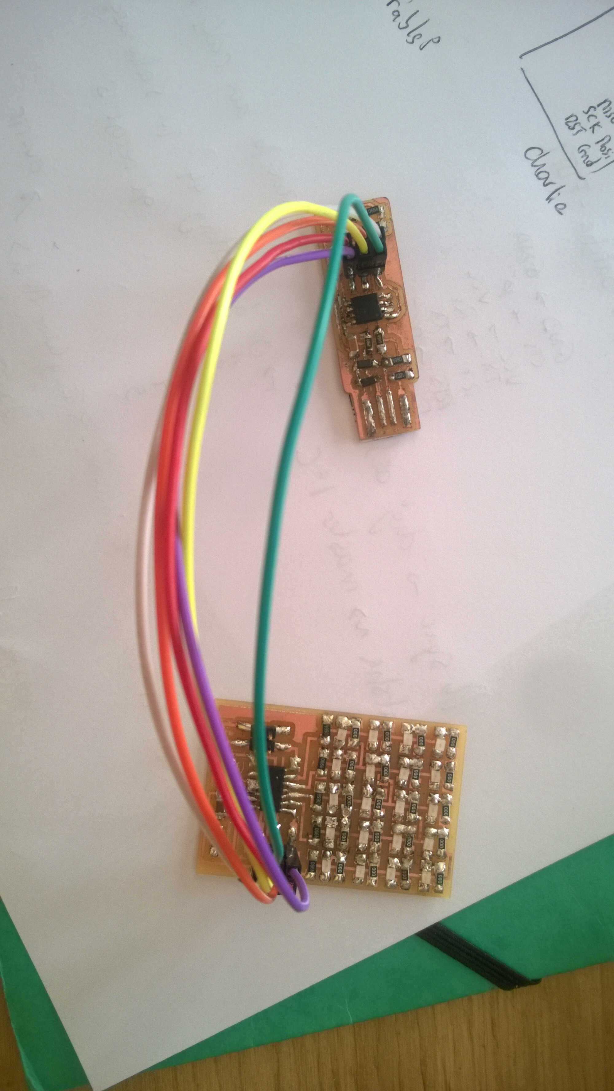
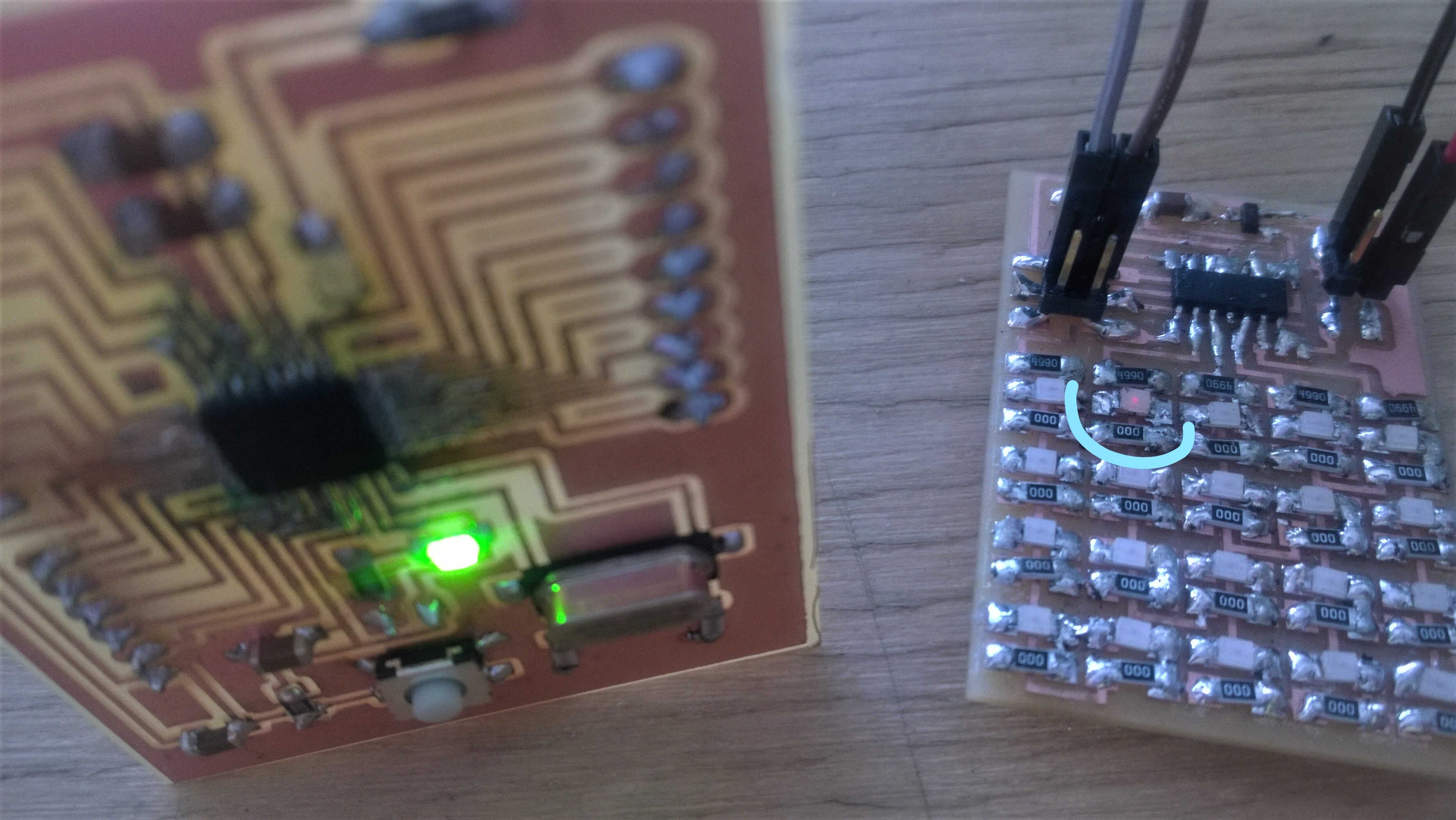
Once both sketches were loaded I linked and powered both boards through a breadboard so that they have common ground.
SDA/SCL Satshakit to Charlieplexing board
powering and common ground
Once done I noticed that on Charlieplexing board the Led directly linked to the SCL pin lit up. None blinked. The lit up led could be an indicator of intern pull-up resistance activated on SCL pin. It would be interesting to use a multimeter to see which pin acts as the ground.
Debugging
I tried to debugg.
1. I changed the master sketch so the 13 led lights up when the transmission starts and got switched off when the transmission is over. I displaced the line switching off in the code to see if it was entering the loop. The led stayed on, the transmission can't be ended for some reasons.
2. I understood that endTransmission returns 0 if the transmission ends successfully. I wanted to check this. I got a 0 when loading the sketch but couldn't get one when connected to CharliePlexing. It was as if the loop was stopped.
3. As I was unsure which pins were used for I2C in TinyWireM, I looked at the library code with code Bender. Attiny44 didn't seem to be suported, I read that some version of TinyWireM were modified for Attiny44 (ex Christensen's version) but not the one provided in Arduino IDE, the adafruit version. I decided to switch to TinyWireS. In TinyWireM called function nevertheless I noticed commands to switch on the pull-up internal resistance. It would be interesting to see if this is the same in TinyWireS.
TinyWireS
In the github repository the descrition of TinyWireS library says it simplifies the Rx/Tx ring buffer management but also that some modifications were made so that it is compatible with Attiny44. They are also several versions of TinyWireS. I first tried to use Rambo's but when I tried to add it through the library manager, an error message said this wasn't a proper library. So I downloaded Nadavmatalon's which could be added smoothly.
TinyWireS test
I simply changed the slave sketch. The receive() function needed to be replaced by read().
  #include <TinyWireS.h>   // wrapper class for I2C slave routines
//#include <USI_TWI_Master.h>

//#include "TinyWireM.h"

#define I2C_SLAVE_ADDR  0x26            // i2c slave address (38)
#define LED1_PIN         0
#define LED2_PIN         1

void setup(){
  pinMode(LED1_PIN,OUTPUT);             // for general DEBUG use

  TinyWireS.begin(I2C_SLAVE_ADDR);      // init I2C Slave mode
}


void loop(){
  byte byteRcvd = 0;
  if (TinyWireS.available()){           // got I2C input!
    byteRcvd = TinyWireS.read();     // get the byte from master

            if(byteRcvd == 5){
              digitalWrite(LED1_PIN,HIGH);
              delay(1000);
            }
            else{
              digitalWrite(LED1_PIN,LOW);
            }
  }
}
I obtained the same result as with TinyWireM.
result + led lightening up
Debugging
I had some doubts about the SCL/SDA pin of the Satchakit so I tried using an Arduino. Once again with the same result. The next tests could be:
1. Checking the up and down pins with the multimeter
2. Add a Led as ground on the Charlieboard
3. Try with hello/button board
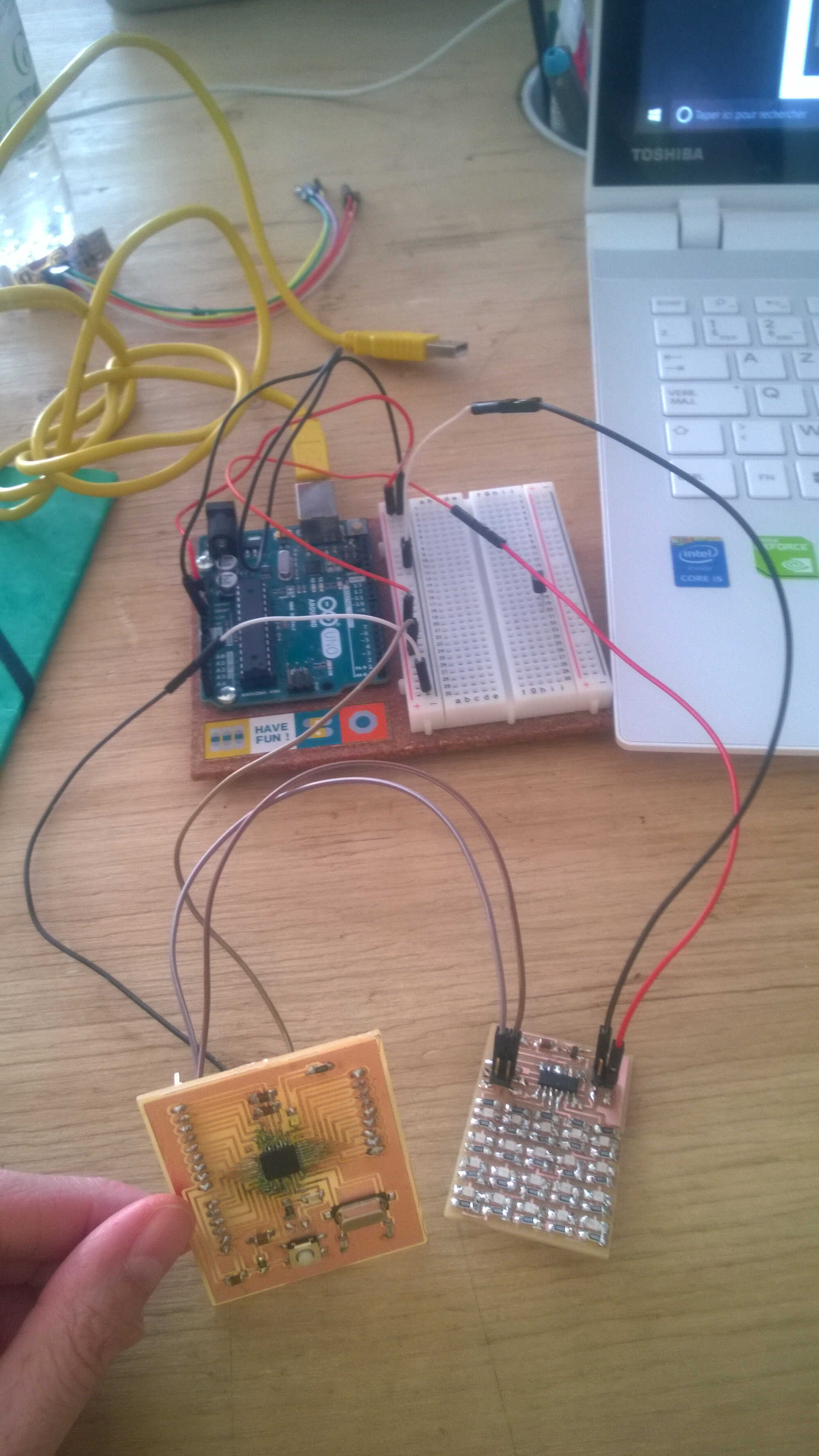
I started with the third test. I loaded the same sketch as for the Charlieboard except for the led pin number -now 7-. Also I noticed SCL/SFA indication on Arduino board, so I used those connectors.
wiring hello board
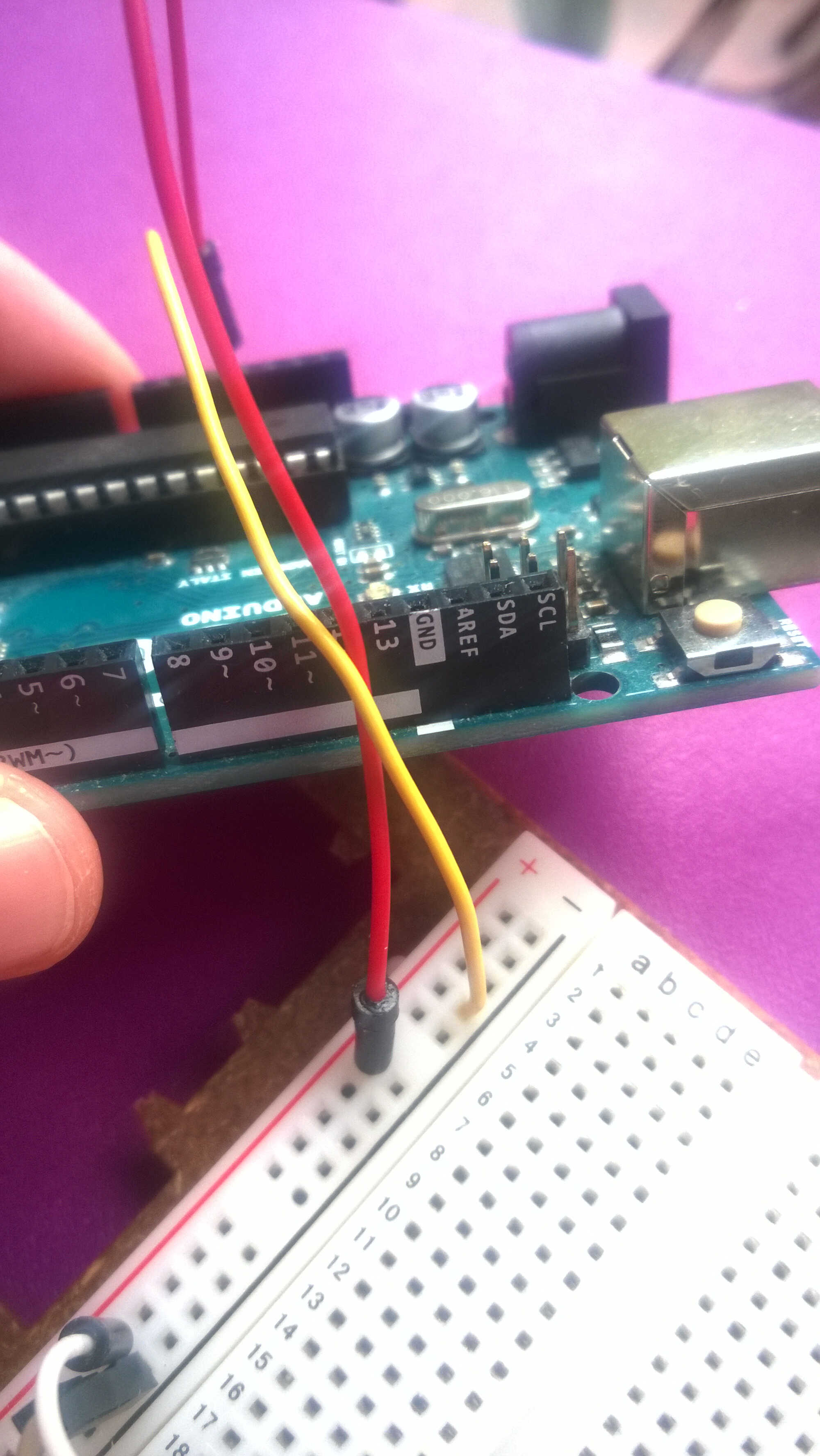
SDA/SCL Arduino connectors
I was pleased to see the led lighting up. I could see the Arduino led blinking as transmission started and ended as well. The only unexpected behaviour was that the slave led stayed on. To check if the loop was running ok, I modified the Arduino sketch so it outputs x, the counter, to the serial monitor. I could witness that the loop ran perfectly.
I then added a loop delay in the master sketch and finally I could see a blink. The delay(1000), once x=5, in the slave loop made it impossible to witness the led turn-off. Now that I could see that the sketches worked fine and that external pull-ups were not required it is time to go back to CharliePlexing.
I mixed Neil's code to the one I was using for the slave. I am still unclear on what Neil's code is doing defining 2 pins as input then as output. I first thought one pin was input when the other was output.
  #include <TinyWireS.h>   // wrapper class for I2C slave routines

#define I2C_SLAVE_ADDR  0x26            // i2c slave address (38)
#define LED1_PIN         0
#define LED2_PIN         1
#define output(directions,pin) (directions |= pin) // set port direction for output
#define input(directions,pin) (directions &= (~pin)) // set port direction for input
#define set(port,pin) (port |= pin) // set port pin
#define clear(port,pin) (port &= (~pin)) // clear port pin
#define led_port PORTA
#define led_direction DDRA

void setup(){
  pinMode(LED1_PIN,INPUT);             // for general DEBUG use

  TinyWireS.begin(I2C_SLAVE_ADDR);      // init I2C Slave mode
}


void loop(){
  byte byteRcvd = 0;
  if (TinyWireS.available()){           // got I2C input!
    byteRcvd = TinyWireS.read();     // get the byte from master

            if(byteRcvd == 5){
              set(led_port,PA4);
              clear(led_port,PA1);
              output(led_direction,PA4);
              output(led_direction,PA1);
              delay(1000);
              input(led_direction,PA4);
              input(led_direction,PA1);
   }

            else{
              digitalWrite(LED1_PIN,LOW);
            }
  }
}
With this code + the delay corrected earlier I was able to see leds blink. This indicated that the SCL pin could be turned off, giving hope for outputting all the 20 combinations. I started testing all the combinations involving the PA4 pin. But the PA1 pin was the one the sketch made blinking -this was a bit by accident-
PA1/PA4 made the first led of the second row blink (Attiny being at the bottom)
PA4/PA2 made the second led of the second row blink
PA4/PA3 made the firsr and the second led of the second row blink
PA4/PA5 made the first led of the second row blink I noticed in all cases a weak brightness of the led and when I upload the code a very bright pattern flashes.
I then tried a combination without PA4, PA1/PA2, I noticed a strange phenomenon: the first led of the 5th row was blinking very brightly, the third of the same row was blinking weakly at a higher frequence and the second led of the second row was weakly blinking in sync with the bright led. This illustrates that I have 2 simultaneous blink. I need to simplify the code. One possible reason is that the voltage get splitted between the 2 weak leds.
Next I will have to make a sketch exploring the different combinaison possible.
Flashing Attiny44
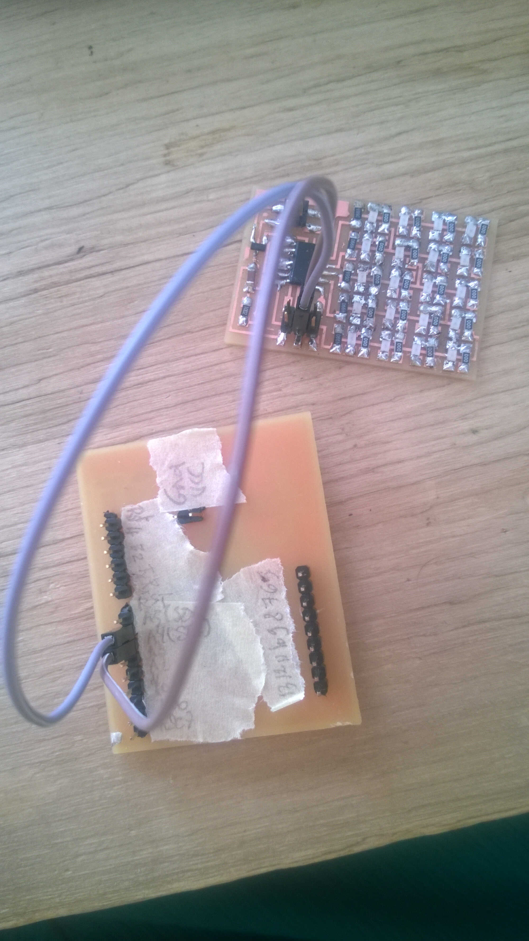
I then decided to interface my led+button board from Week 8 (schematics + board). To do so I needed to build a serial communication protocol in the software of the Attiny 44. This could be done with the library SoftwareSerial.h. Rx and Tx pins can be assigned to the pins of choice. My code output the button state to serial.
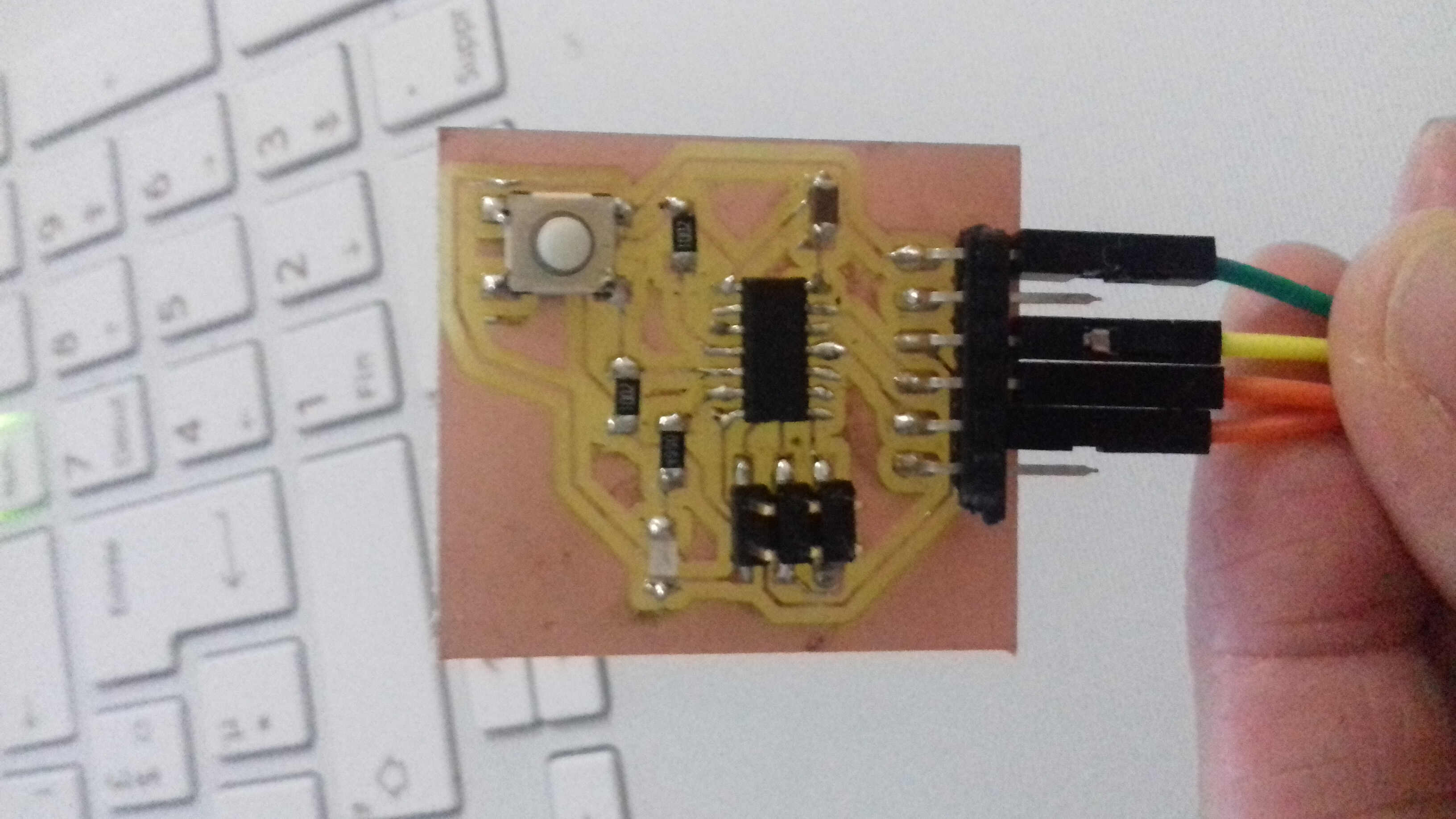
serial wiring
I programmed the Attiny 44 with the following code:
#include <SoftwareSerial.h>
#define rxPin PA1
#define txPin PA0
#define led PA7
int sw_pin = 5;
int sw_value = 0;

SoftwareSerial serial(rxPin, txPin);


void setup() {
  // put your setup code here, to run once:
pinMode(rxPin, INPUT);
pinMode(txPin, OUTPUT);
pinMode(led, OUTPUT);
pinMode(sw_pin, INPUT);
serial.begin (1200);
serial.println("hello");
}

void loop() {
  digitalWrite(led, HIGH);
  // put your main code here, to run repeatedly:
  sw_value = digitalRead (sw_pin);
  //serial.println("hello");

if(sw_value==0){
  serial.println("0");
}
else{
  serial.println("1");
}
delay(100);
}
It took me some time to make it work as I used another type of pin index (1,2,3...) and those indices didn't get recognized. Also I made the mistake of selecting the wrong internal frequency (1MHz instead of 8), which output square instead of values. Once all fixed I received 0 and 1 on the Arduino IDE serial monitor at 1200 bauds.
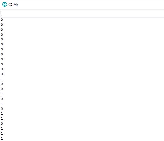
Arduino Serial monitor
Processing
I then went to Processing to make good use of the serial output thanks to processing.serial. The button state will be used to pause on a picture among two animated one. I am making good use of the bouncing of the button which animates 2 images.
import processing.serial.*;

PImage bImage;
PImage bImage2;
Serial myPort;
int val;

void setup(){
  val=0;
  println(Serial.list()[0]);
  myPort = new Serial(this, Serial.list()[0],1200);
  size(600,450);
  bImage = loadImage("mov3.png");
  bImage2 = loadImage("mov2.png");
}
  void draw(){
    while(myPort.available()>0){
      int lf = 10;
      String stringval = myPort.readStringUntil(lf);
      println(stringval);
      try{
        if(stringval != null)
        {
          val = Integer.parseInt(stringval.trim());
        }
      }
      catch(NumberFormatException ex)
      {
        val = 1;
      }
      println(val);
    }

    if(val == 0){
      background(bImage);
    }
    else{background(bImage2);
    }
    delay(10);
  }
I found the stringval part online; it acts as a buffer. Without it I only had 0 as income in Processing. readStringUntil reads characters from the serial buffer into a string. The function terminates if the terminator character is detected , here 10. parseInt parses a string and returns an integer. It looks for the next valid integer in the incoming serial stream. In a way it is avereaging the string.
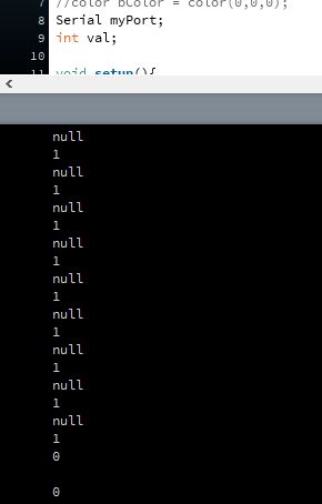
Processing Serial monitor
Here the interface in motion, where I switch images with the button:
Source file to load here
Regional
This week was also a small comitee/male one, it was the Belgians and me.
Denis showed a stunning production as often. He build a Fibonacci puzzle and the image recognition interface to help solving it. He used imageJ for image processing based on colour threshold. For the colour detection he picked HSV over RGB. With a camera linked to a Raspberry he took pictures of his puzzle on a blue textile. He coded the whole thing in Python with the PiCamera library. There were some discussion on the possibility of building our own Raspberry. It was judged too difficult.
Jeremy was running late but build a slider to control motors. He didn't like the adjustements needed in Arduino sketches to fit Processing.
Victor linked a potentiometer to a temperature indicating interface. he me,tioned Firmata, I am still unsure on how to use this library. I will research this.
Myself showed my tests, mentionned serial reading discrepancies and encoding. Marco, Thomas and Roman appreciated the fact that I tried different methodology. I will have to redo it with a board of my own.