Abstract
This week was about making boards/microcontrollers talk, following different protocols, through wires and wirelessly.
Some of the question raised were:
- What are the differences between the communication protocols?
- What communication can a ATMega 328P/ a ESP8266 handle?
I mainly used 1 workflow:
Eagle > Fabmodule > VModel > Arduino IDE
My biggest achievement:
My biggest struggle:: Hardware
Missing material
| SMD interruptor |
Chronology
| Thursday | Friday | Monday | Tuesday | |
|---|---|---|---|---|
| Fablab festival | Satchakits | Fixing Satchakits | Wifi board desgin | |
| Wifi board fabrication |
Setup
| Softwares | Fonction |
|---|---|
| ESP8266.lbr | Eagle addition |
| ESP8266 board | Arduino IDE addition |
Skills acquired
Asssesment validation
Fablab Festival
Francesco from Volumes came to WoMa and asked us if we were going to the Fablab Festival the coming week. That's how I learned about this festival. I already had a week-end planned, the only day I had left was Thursday -in order to catch up networking the Friday-. From my understanding a Fablab is as much about knowledge, technical skill as about the community. This aspect was not really covered so far, so I rushed to the airport for an express visit of this festival.

Thursday morning

the outside

the inside
I arrived the morning of first day-dedicated to Fablabs- while the annual general meeting was taking place. So I discovered the Réseau français des Fablabs. It is still a small association regrouping 30 Fablabs, users and supporters which is considering hiring its first employee. Now most of the revenue is generated from volunteering. This gave an overview of the French Fablab ecosystem. WoMa will now been part of the supervisory board from now on. After the annual meeting I visited the place, the festival was taking place next to Artilect-a Toulousian Fablab-. I asked for a tour to several organizers without success, but from what I saw I is a well equiped lab, quite interdisciplinary.

Artilect art, mentionned in Neil's class
collective jam
reminder of composite week
I saw several nice projects:
- bio-oriented projects (spiruline/kombucha production; silkworm breeding, indoor greenhouse)
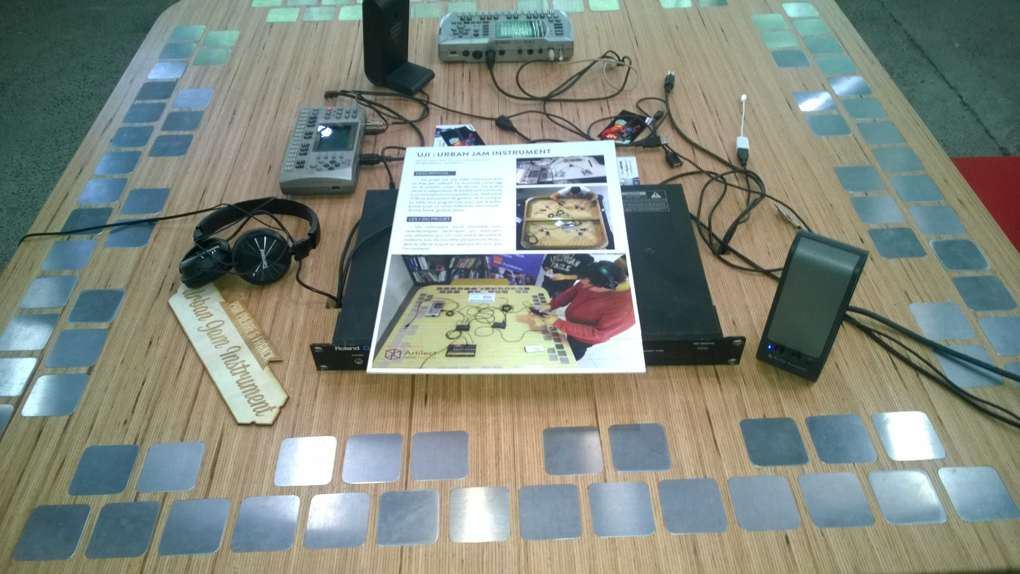
- a jam table
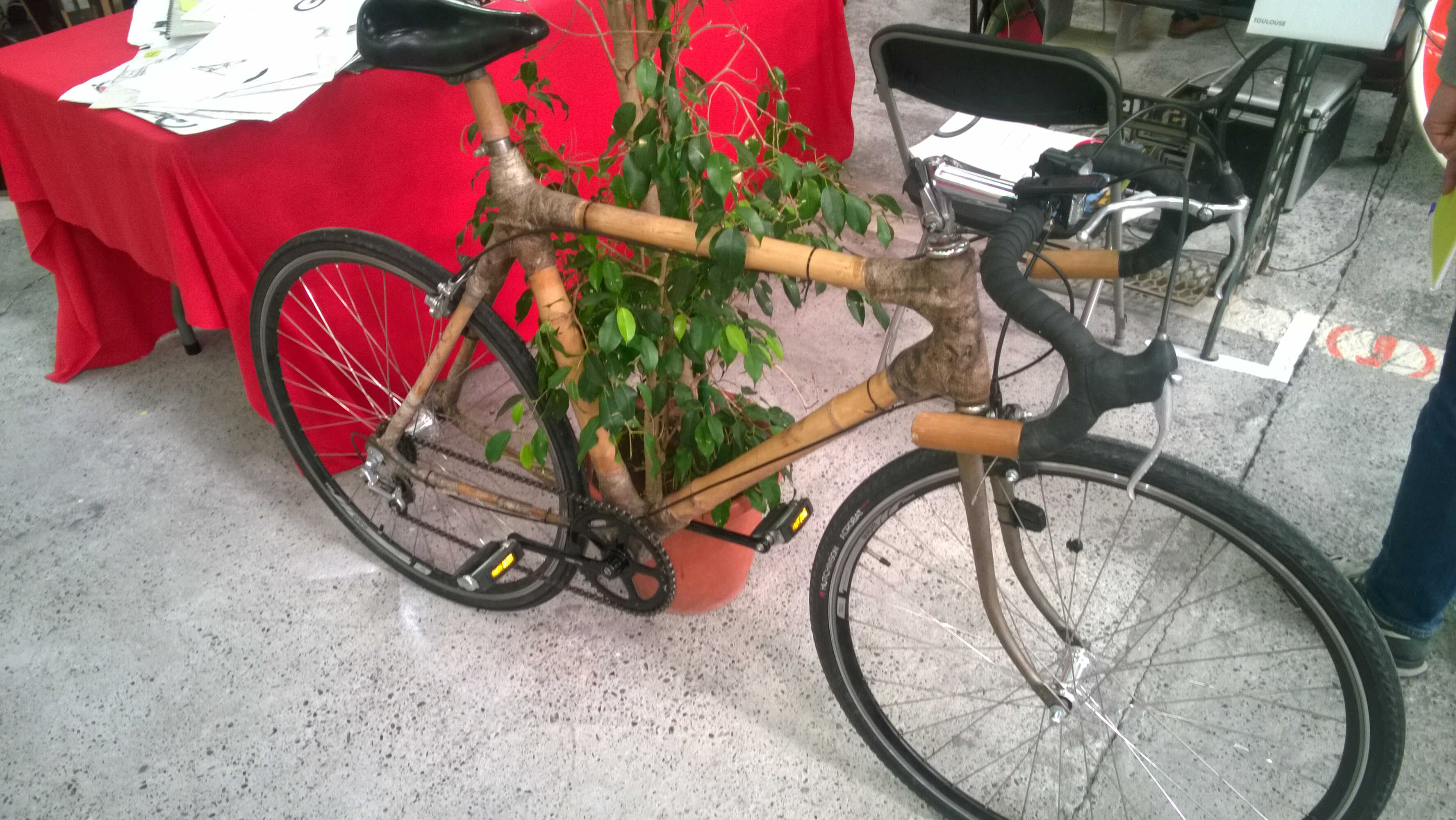
- bikes made from bamboo and composite (epoxy)
- a foldable 3D printer By Flow

reminder of the week
The afternoon I took part in a bar camp on "Fablab vs. waste" while other worked on Fabcity, Fab13, 3D food... The discussion was directed by a transport expert who created a kit based on a material made out of old tires. One of conclusion was that a Fablab is not meant to become a recycling center but rather is aimed at taking advantages of undervalued material. After the rendition I still had time for some presentations/chats as the one given by Waag- which as I learned also has a BioHack Academy. And off I went to Network week.
Comparison
It is important to understand what differenciate communication protocol -in short. I found various sources who did such comparisons:
- this blog.
- this advice on stackoverflow "It depends of your total requirements and how expensive are pins. I2C only needs two pins, but it's slow and to handle it with or without interrupts is a pain, even with the build in peripheral modules. It's a master/slave system, it's good for controlling many slow devices like temp sensors. Uart needs two pins, it's normally faster, easier to handle, but requires (nearly) the same clocks at both sides. One to one asynchronous system, can be good if both systems needs to be send sometimes data without waiting for a master poll request. SPI needs 3 (or 4 with CS) pins, it's the fastest, simple to implement even with DMA, low cpu time overhead, often buffered. When you have enough free pins I would prefer it."
- this SPI vs. I2C
- a Bluethooth vs. Wifi comparison
Despair
In short, I build Satchakits, burned their bootloaders -after so many troubles-, I could load a blink sketch into one of them...once.
Aim was to establish I2C between them.
First Satchakit
One pin of the first Satchakit was damaged during soldering (a GND pin), I thought it was damaged for good so I rebuild a Satcha from scratch.
I accidently wired this board to burn the bootloader and it finally worked.
I could also load through the FDTI convertor the blink sketch but the voltage on the pin is oscillating on a strange range [-3-1V].
I tried to find an explanation in the ATTiny 328P datasheet.
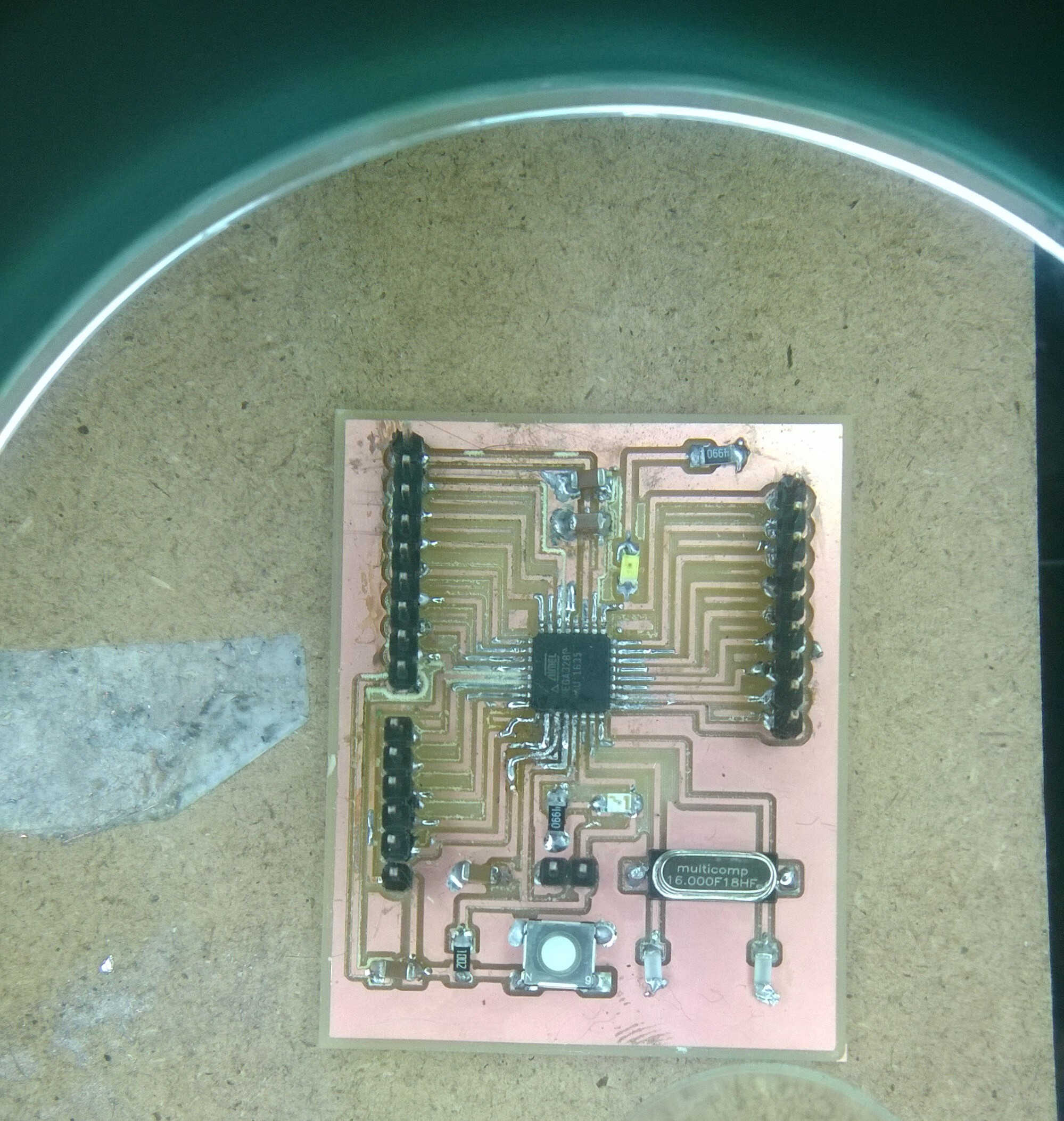
milled and damaged satchakit n°1
Second Satchakit
I burned the bootloader of this board more easily but could only load a sketch from FDTI once.
It worked while I was rearranging the wires. I read some posts about disconnecting Rx/Tx while uploading but could reproduce the phenomenon.
I am apparently not the first struggling with this issue as I saw many posts on the same error code online (not in sync).
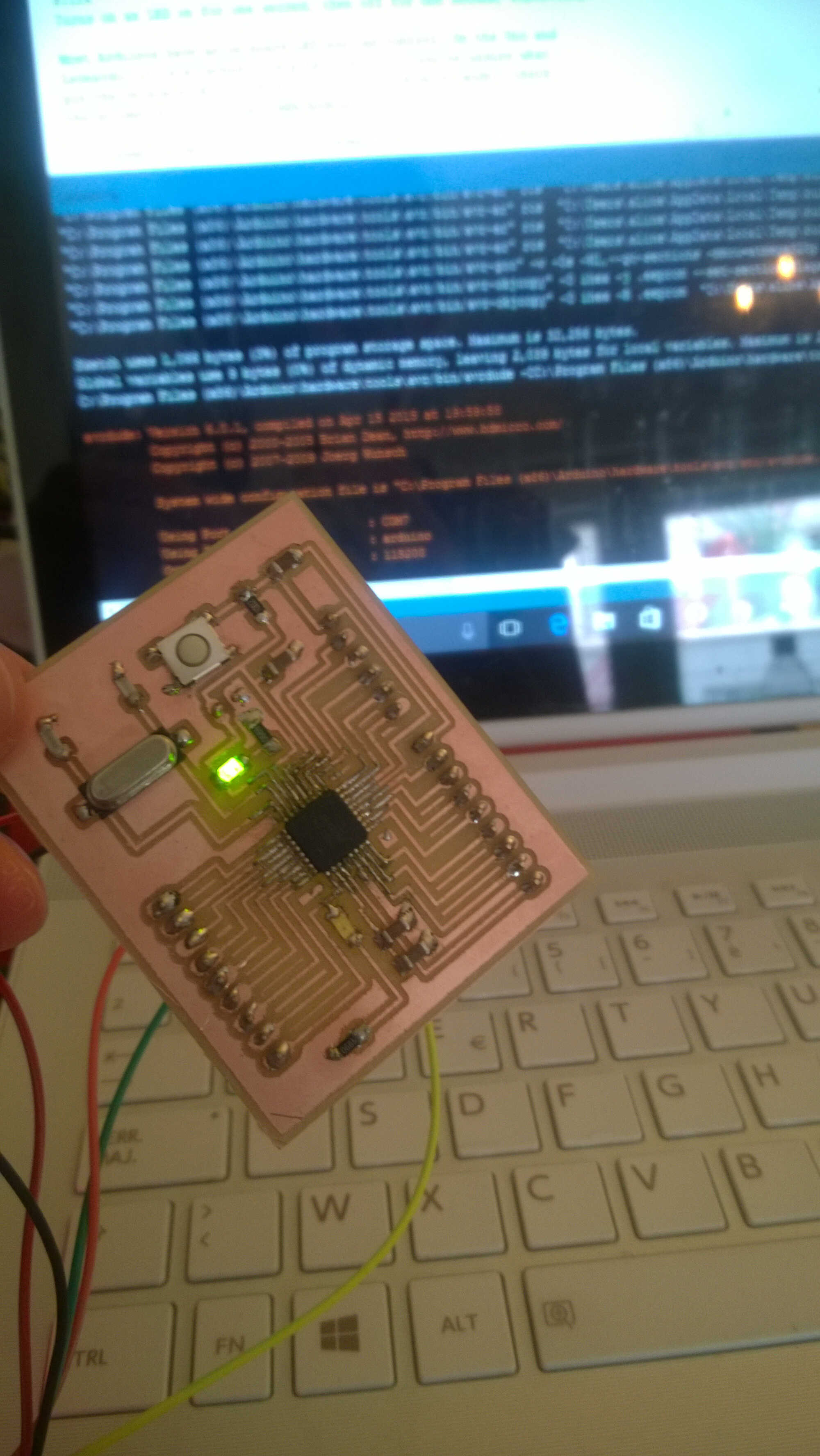
milled and powered satchakit n°2
Based on one of the advise on this blog I reflew some pins solder (among other the AtMega DRX pin) and it ended up working.
The next step would now be to design my own satchakit. I would like build a modular one with adaptive shields.
In short, I build Satchakits, burned their bootloaders -after so many troubles-, I could load a blink sketch into one of them...once. Aim was to establish I2C between them.
First Satchakit
One pin of the first Satchakit was damaged during soldering (a GND pin), I thought it was damaged for good so I rebuild a Satcha from scratch.
I accidently wired this board to burn the bootloader and it finally worked.
I could also load through the FDTI convertor the blink sketch but the voltage on the pin is oscillating on a strange range [-3-1V].
I tried to find an explanation in the ATTiny 328P datasheet.
milled and damaged satchakit n°1
Second Satchakit
I burned the bootloader of this board more easily but could only load a sketch from FDTI once.
It worked while I was rearranging the wires. I read some posts about disconnecting Rx/Tx while uploading but could reproduce the phenomenon.
I am apparently not the first struggling with this issue as I saw many posts on the same error code online (not in sync).
milled and powered satchakit n°2
Based on one of the advise on this blog I reflew some pins solder (among other the AtMega DRX pin) and it ended up working.
The next step would now be to design my own satchakit. I would like build a modular one with adaptive shields.
One pin of the first Satchakit was damaged during soldering (a GND pin), I thought it was damaged for good so I rebuild a Satcha from scratch. I accidently wired this board to burn the bootloader and it finally worked. I could also load through the FDTI convertor the blink sketch but the voltage on the pin is oscillating on a strange range [-3-1V]. I tried to find an explanation in the ATTiny 328P datasheet.
milled and damaged satchakit n°1
Second Satchakit
I burned the bootloader of this board more easily but could only load a sketch from FDTI once.
It worked while I was rearranging the wires. I read some posts about disconnecting Rx/Tx while uploading but could reproduce the phenomenon.
I am apparently not the first struggling with this issue as I saw many posts on the same error code online (not in sync).
milled and powered satchakit n°2
Based on one of the advise on this blog I reflew some pins solder (among other the AtMega DRX pin) and it ended up working.
The next step would now be to design my own satchakit. I would like build a modular one with adaptive shields.
I burned the bootloader of this board more easily but could only load a sketch from FDTI once. It worked while I was rearranging the wires. I read some posts about disconnecting Rx/Tx while uploading but could reproduce the phenomenon. I am apparently not the first struggling with this issue as I saw many posts on the same error code online (not in sync).
milled and powered satchakit n°2
Based on one of the advise on this blog I reflew some pins solder (among other the AtMega DRX pin) and it ended up working. The next step would now be to design my own satchakit. I would like build a modular one with adaptive shields.
Excruciating despair
Ideation
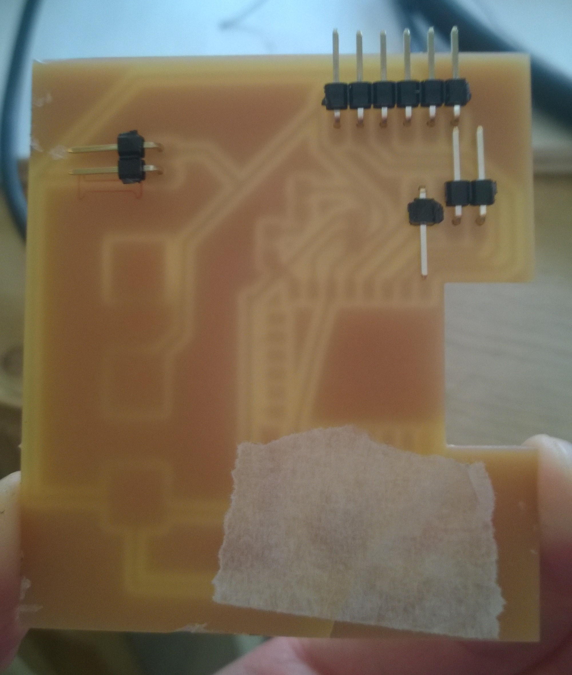
In short I designed a board to host a ESP8266. At first I planned to use Neil's one but we don't have a 3.3 voltage regulator this size. So I started redesigning the board. I decided to go without voltage regulator as there is a voltage switch on the FDTI convertor. Then I added a support for coin battery to make it wireless. Then I read the documentation Thomas send us. I realized some pins should be able to change state (which was not provided in Neil's board), could this be done through code? In case it wasn't I added a button to the reset and a pin to GPIO0. I also added pins to I2C handling pins (GPIO4/5) and a LED to GPIO15 -inspired by the documantetion I found on ESP8266Ex. The Led is there to attest communication.
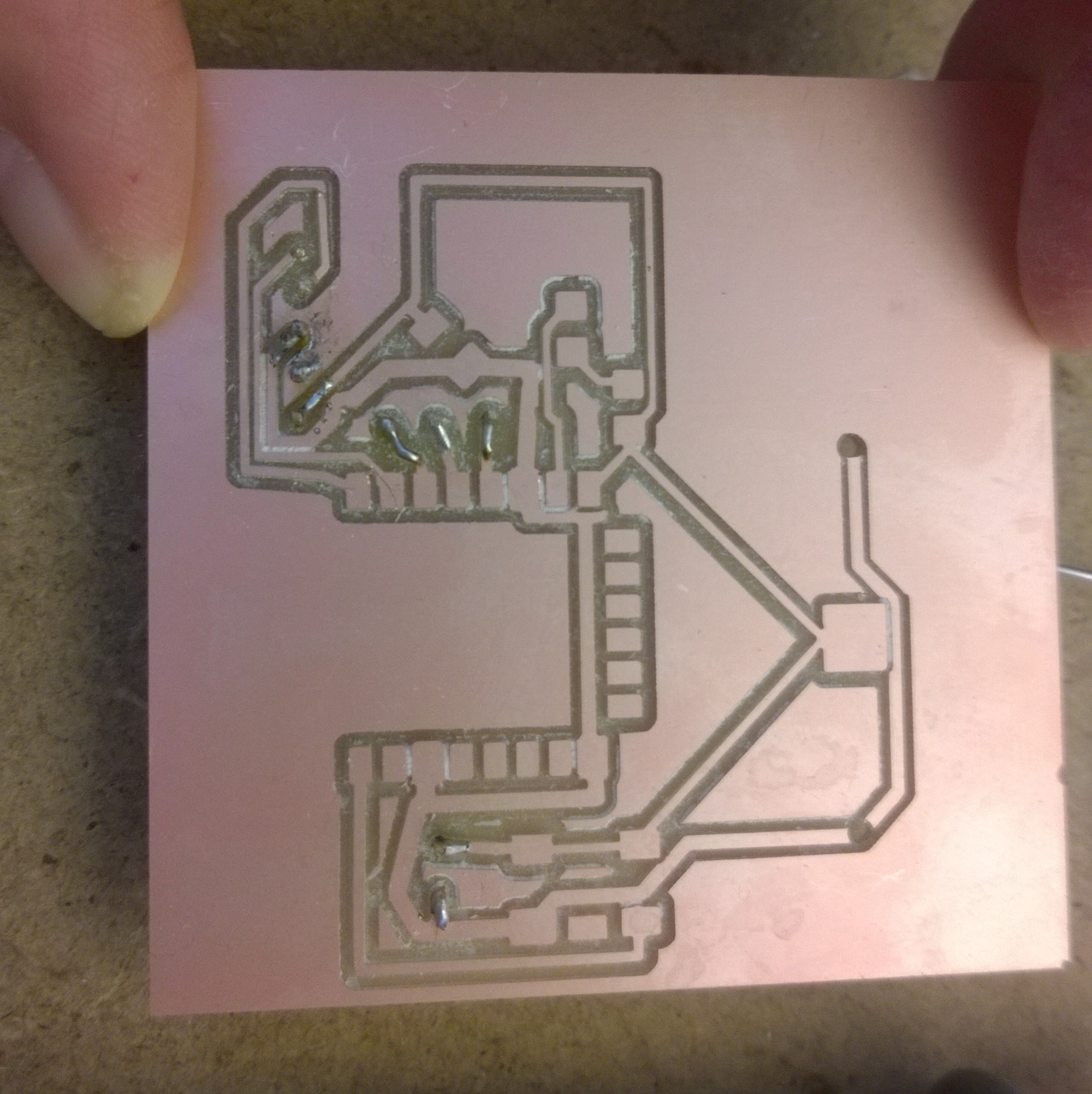
Board design
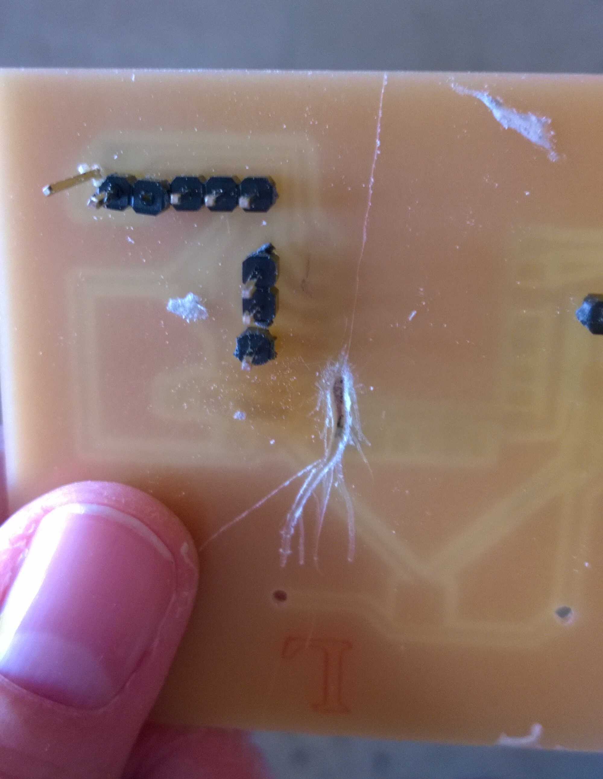
I used Eagle and its autorouter to sketch my traces. I should have reworked them for 30 mn more in order to have wider tracks and away from any risk of short. A short happened after soldering between GPIO15, when connected to the current the LED lights up. This Led I added a bit randomly indicated me the issue. With GPIO15 I can't load a new sketch -or this may be only one of the reasons. The short happened under the board, in a inaccessible place and the board cant be desoldered with hot air. I tried an extrem rescue: From below, digging to the short likely place.
Here is the chronology of my wifi board:
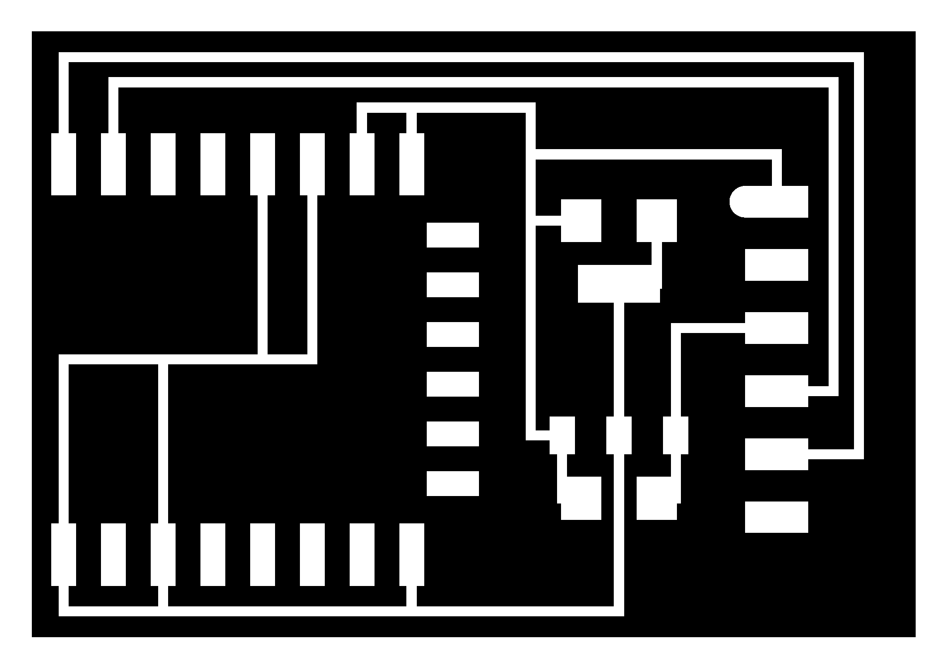
Neil's wifi board with regulator
version with a small coin cell holder + button + led + connectors
version wih a 28 mm coin cell holder + led resistor
As I used the autorouter some tracks are quite close, I wonder how to ask the autorouter to "take more place". Here are my board milled, I checked carefully for shorts with a multimeter and corrected with a cutter blade when neeeded.
milled version v2
milled version 3 with pins soldered
I am planning to redesign this board with anoter type of connector (some letting more place to solder). Also I noticed a risk of shortage below the coin battery, ground and vcc should not be this close under it. I will redraw the VCC track around the cell.
despair benchmark
2 weeks later I drew a new autonomous Wifi board. The requisites for this board were the following:
-a FTDI connector
-an output-a led + its protective resistor-
-an anaolog input-a phototransistor + a 10kOhms resistor-
-a I2C connector
-a shape so that the wifi antenna isn't located above copper
- a coin battery support with no risk of cut
- traces as far from each other to reduce the short cuts risk
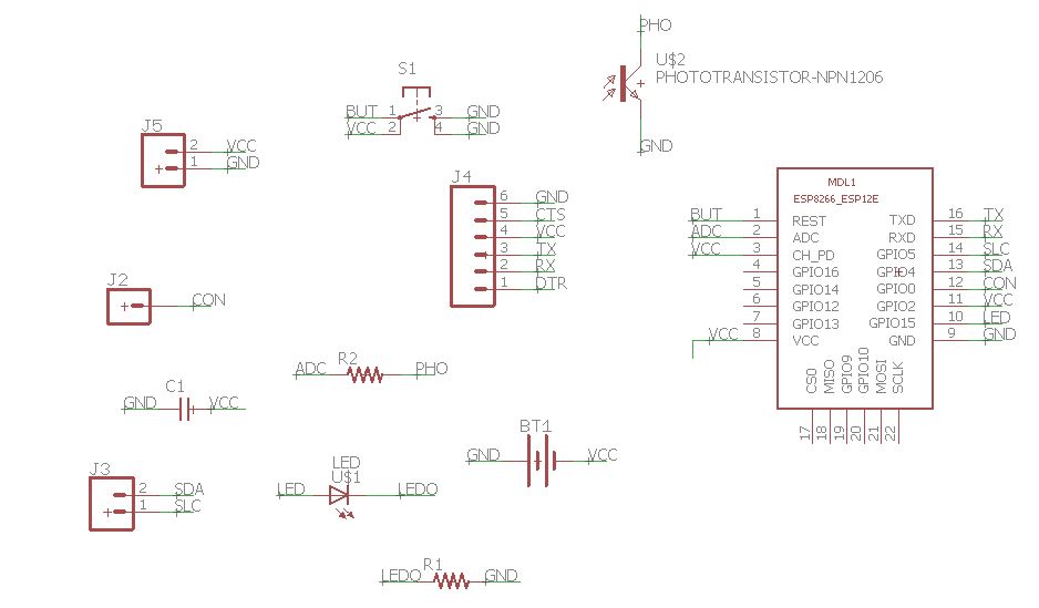
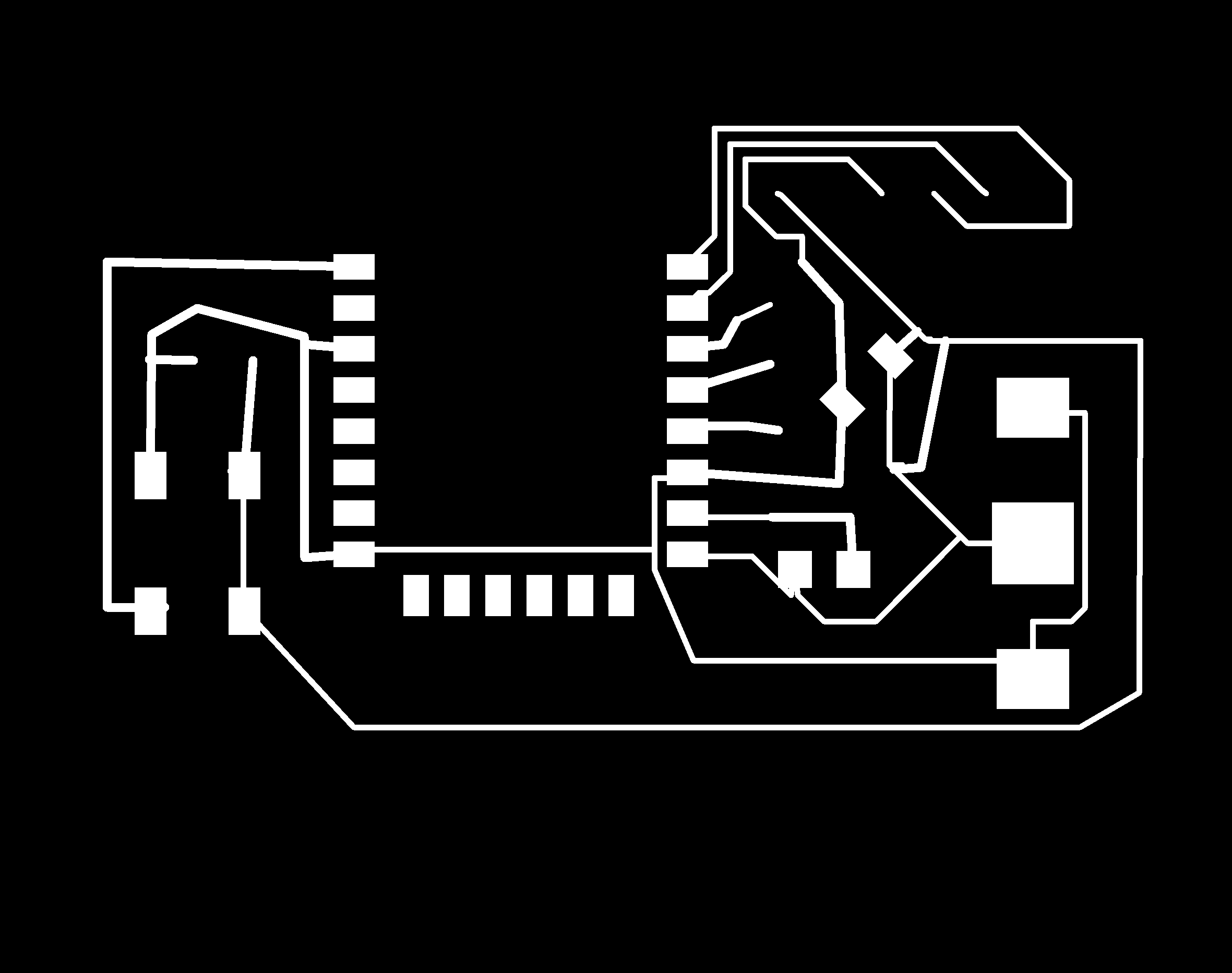
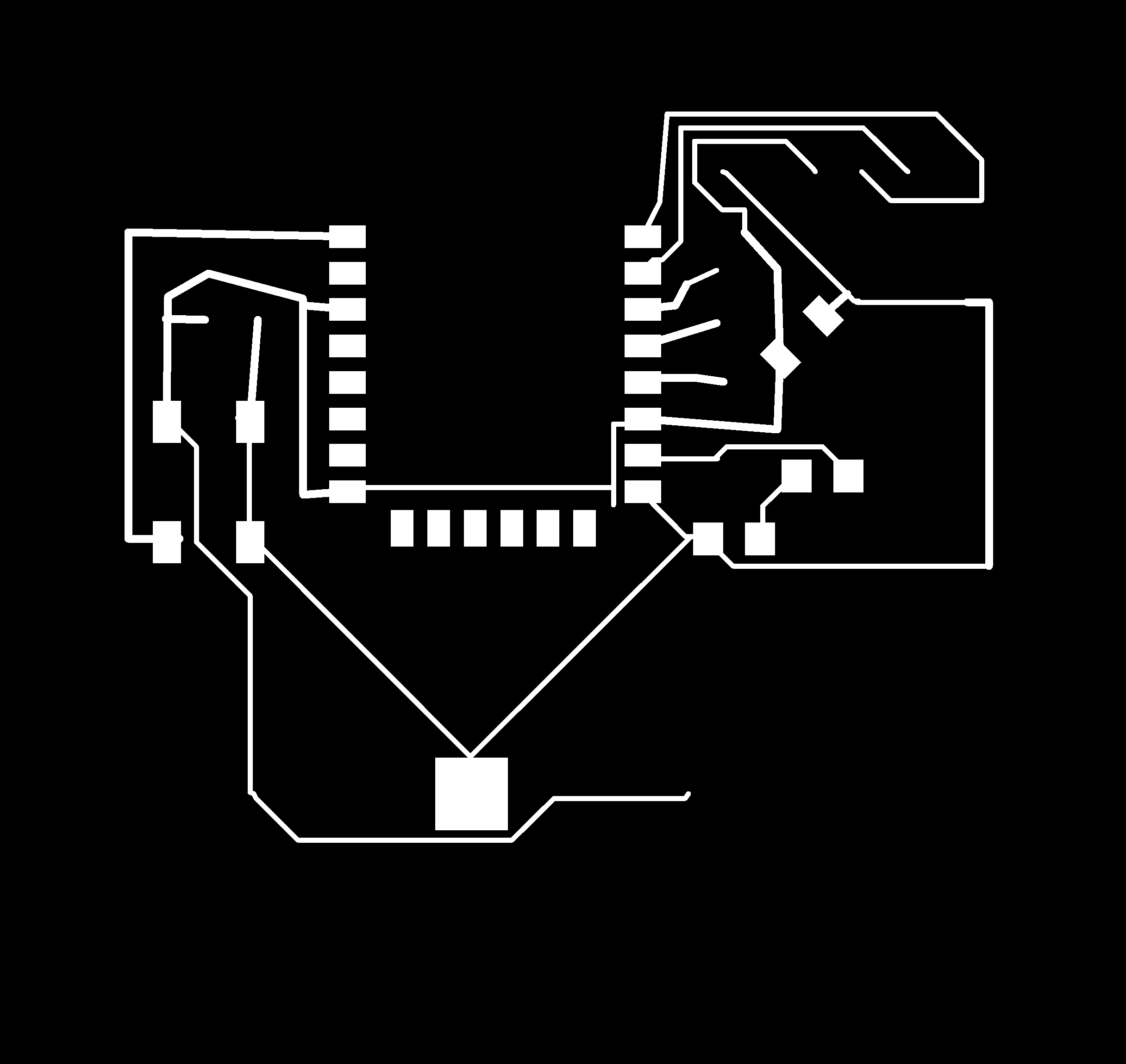
schematics of the revised wifi board

board view of the revised wifi board
Source files could be loaded here.
As I milled it I noticed an usual sound coming from the milling machine and the mesh broke. I am still investigating what might have gone wrong. I wondered if this could be due to an error in fabmodule. I might have selected cutting instead of traces. To check this I opened the .rmlfile. I found 2 websites which helped me read through .rml. The first oneexplained the coordinate system used. The second one was more exhaustive about the acronyms. To summarize:
- PA stands for position absolute
- VS for the velocity
- VZ for the feed rate in Z
- PZ for the setting of Z1 and Z2
- MC for motor control
- PU/PD for pen up/down
- Z for the coordinates Now that I know how to read those files I opened and compared the trace and the outline files. In the trace files the Z didn't go below -10. In the output 3 paths to drill were noticeable at depth of -61, -119 and -170. Based on this observation I don't think the problem was my file and the process selected in Fabmodule.
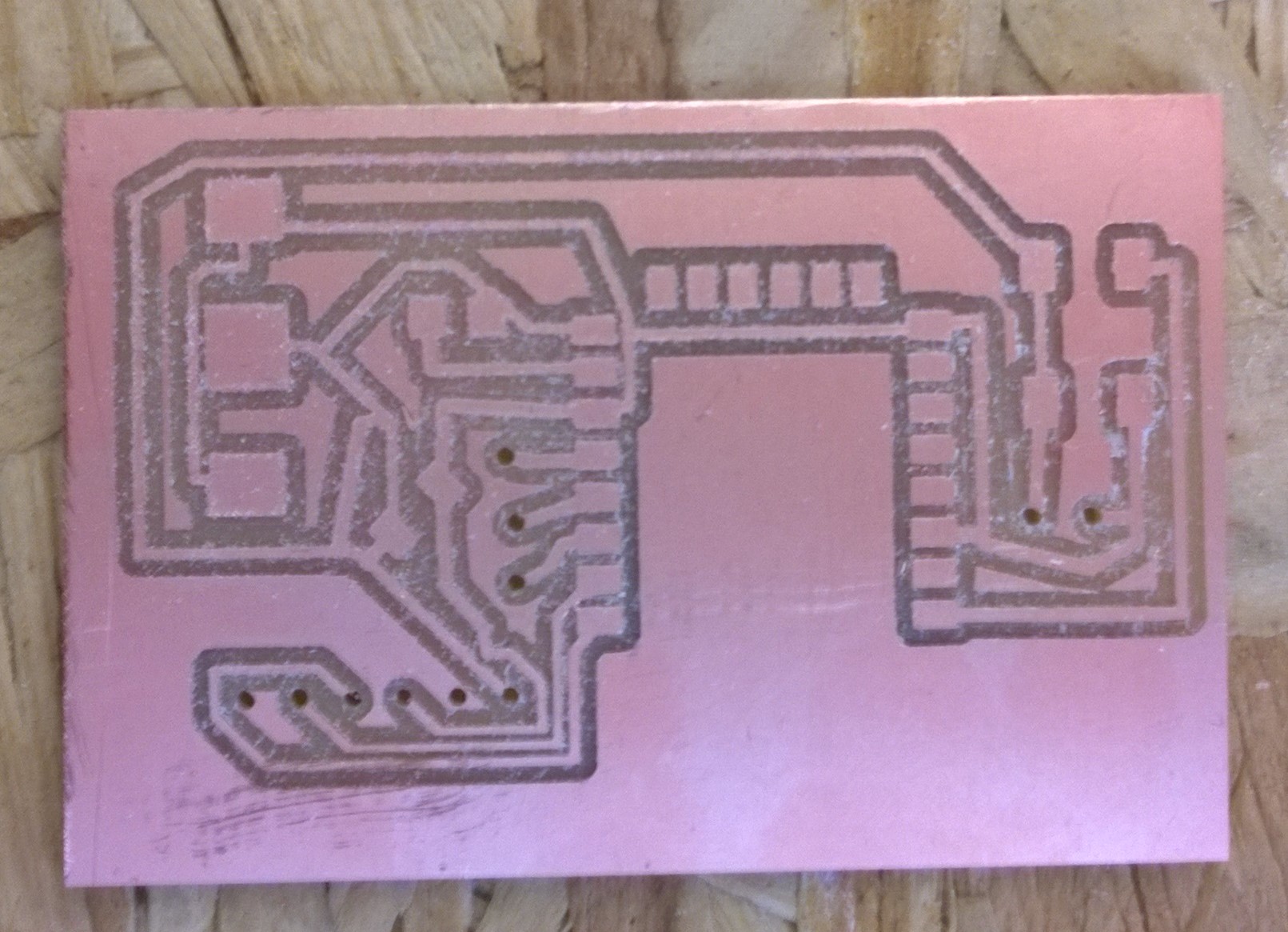
I re-edited the rml, Thomas rescrewed the bed of the milling machine and all worked fine. I recycled most components of the previous board thanks to the hot air gun, except the ESP which I soldered too thorougly. I only soldered the connected pins on the v2.

recycling components
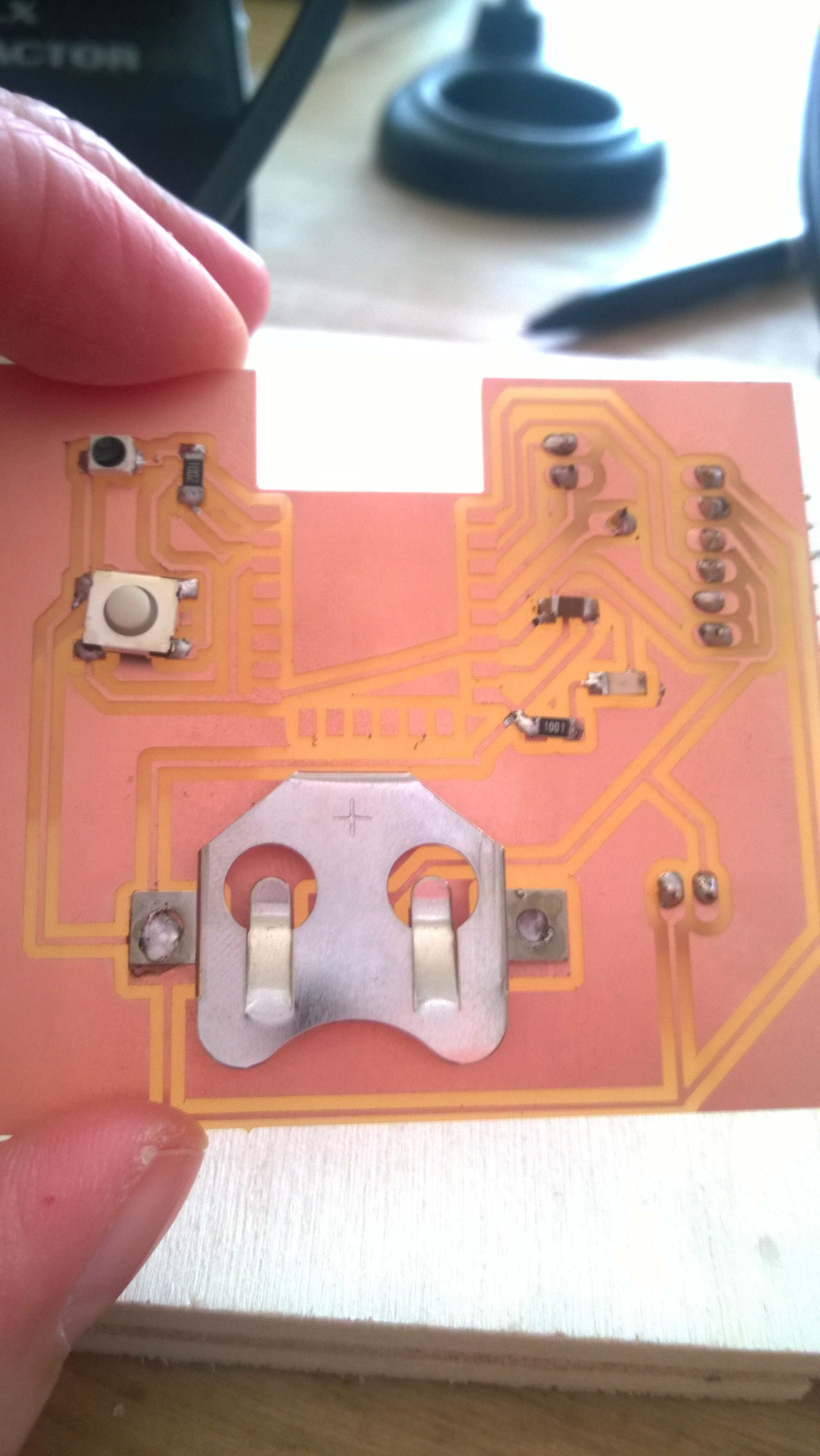
traces -front view
back view
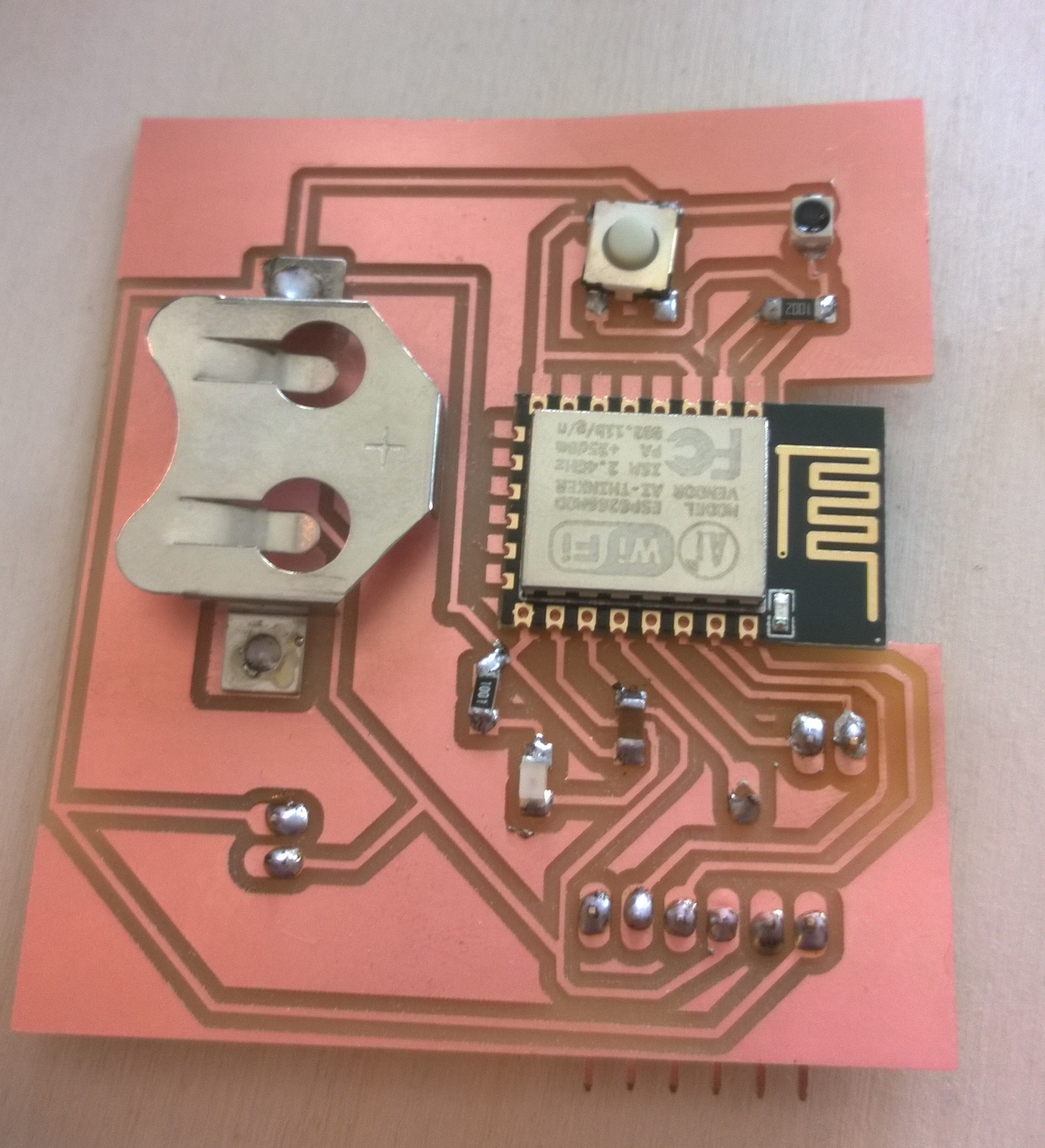
soldered
Once I soldered the board I could load the sketch. To do so I had to plug the board to the FDTI/USB convertor (GND, VCC, TX/RX, RX/TX) and the GPIO0 pin on GND on the back of the board. In a next version a switch would be nice.
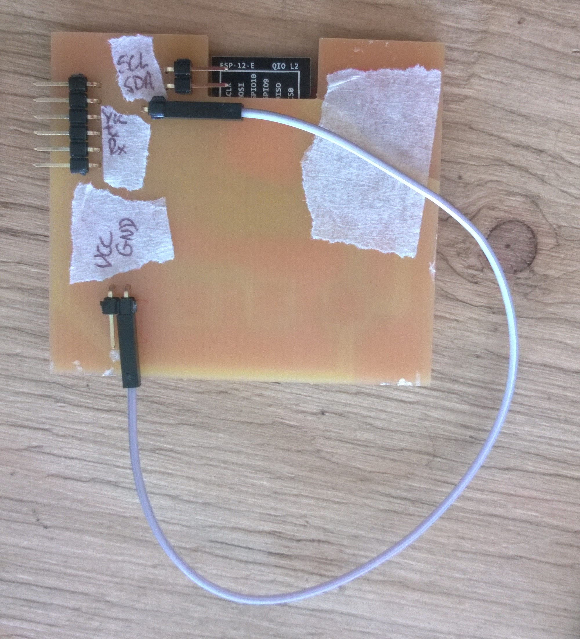
GPIO0 to GND
I unplugged the board, connected GPIO0 to VCC, replugged the FTDI/USB and opened the serial monitor. It dislayed nothing until I tried the reset bouton, which worked. Non-sense characters appeared. I selected the wrong baud rate. Once the baud rate corrected, the serial monitored was displaying "...." as it wasn't able to connect to the wifi. The case I used for the ssid wasn't correct. After those small mistakes the board worked smoothly. From the serial monitor I could get the IP adress to check that the board worked as a server.
I then tried the connection switch, where by going to a specific adress I could turn led on and off. I had to do mild modification of the code for it to work. I didn't pay attention but the pin I connected my led to is GPIO15. This pin is linked to a pull-down resistor and its mode has to defined in the loop for it to switch to output.
      #include <ESP8266WiFi.h>
   #include  <WiFiClient.h>
   #include  <ESP8266WebServer.h>
   #include  <ESP8266mDNS.h>

  // #define RELAY_PIN 15

   const char* ssid = "WoMa"; // remplacer par le SSID de votre WiFi
   const char* password = "WOrkingMAking"; // remplacer par le mot de passe de votre WiFi
   ESP8266WebServer server(80); // on instancie un serveur ecoutant sur le port 80
   void setup(void){
     //pinMode(15, OUTPUT);
     Serial.begin(115200);

     // on demande la connexion au WiFi
     WiFi.begin(ssid, password);
     Serial.println("");
     // on attend d'etre connecte au WiFi avant de continuer
     while (WiFi.status() != WL_CONNECTED) {
       delay(500);
       Serial.print(".");
     }
     // on affiche l'adresse IP qui nous a ete attribuee
     Serial.println("");
     Serial.print("IP address: ");
     Serial.println(WiFi.localIP());
     // on definit ce qui doit etre fait lorsque la route /bonjour est appelee
     // ici on va juste repondre avec un "hello !"
     //server.on("/bonjour", [](){
       //server.send(200, "text/plain", "hello !");
     //});
      server.on("/on", []() {
       pinMode(15, OUTPUT);
     digitalWrite(15, LOW);
      server.send(200, "text/plain", "relay is ON");
     });

    server.on("/off", [](){
     pinMode(15, OUTPUT);
    digitalWrite(15, HIGH);
   server.send(200, "text/plain", "relay is OFF");
   });
     // on commence a ecouter les requetes venant de l'exterieur
     server.begin();
   }
   void loop(void){
     // a chaque iteration, on appelle handleClient pour que les requetes soient traitees
     server.handleClient();
   }
I tried to make the server work autonomously with a battery. Even if the battery delivered 2.8V only 2V could be measured on the circuit and it wasn't enough. There might be losses in the circuit. I will try with a brand new battery and look at commercial traces to get ideas of optimization. Later I could make the code more complex adding the phototransistor readings to it or by plugging an I2C bus at the I2C pins.
LittleBits
As home-made solutions were doomed, I looked at what I had at home. I received LilleBits Cloudbit at Christmas but never got to use it. I thought that might be a starting point. I would continue on Wifi network. I bought an ESP12E devkit as I couldn't unsolder my ESP even after a hot air gun try. The plan was to connect the ESP to my LittleBits through IFTTT. I got the idea reading this post and that one.
To do so several steps were needed:
- Adding a button to my ESP
- Programming my ESP with Arduino IDE
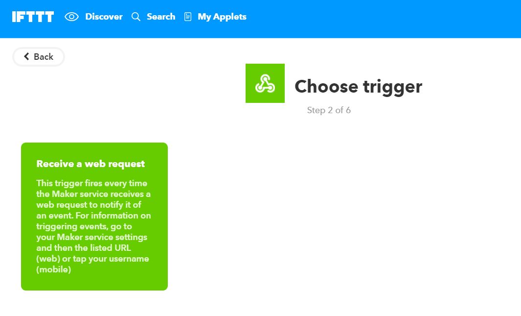
- Understanding IFTTT and creating an Applet
- Understanding LittleBit
- Link the three
I added the button between the GND and the D2 pins. I didn't address a resistance for debouncing so they are some irregularities.
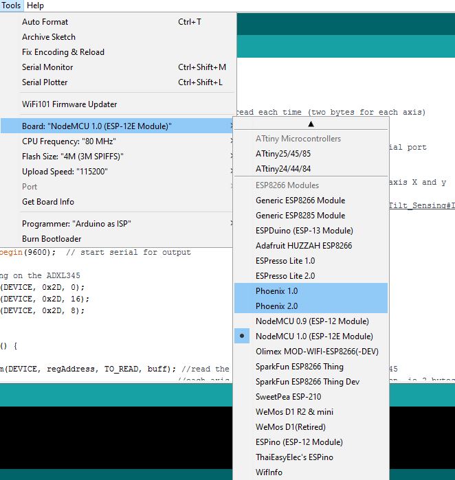
To program the ESP they are Arduino librairies/board managers. The same way Attiny boards were added to the board manager so can be the ESP12E. Meaning by adding a url in the Preferences > Additional Boards Manager URLs. After this, different ESP are available in the board choice. Mine corresponds to the NodeMCU 1.0 (ESP-12E module). Available with the new board are new examples. For this project I also loaded the sketch from ESP8266-to-IFTTTgithub project. It contains script to directly communicate with IFTTT.
DataToMaker.h:
    #include  <Arduino.h>
    #include  <ESP8266WiFi.h>

    #ifndef DataToMaker_h
    class DataToMaker
    {
      public:
        DataToMaker(const char*, String); // constructor
        bool connect();
        bool setValue(int, String);
        void sendToMaker();
        void post();

      protected: // it is protected because the subclass needs access
        //to max distance!

      private:
        void compileData();
        WiFiClient client;
        const char* privateKey;
        String event;
        String value1, value2, value3 = "";
        bool dataAvailable;
        String postData;
    };

    DataToMaker::DataToMaker(const char* _privateKey, String _event)
    {
      privateKey = _privateKey;
      event = _event;
    }

    bool DataToMaker::connect()
    {
      if (client.connect("maker.ifttt.com", 80))
        return true;
      else return false;
    }

    void DataToMaker::post()
    {
      compileData();
      client.print("POST /trigger/");
      client.print(event);
      client.print("/with/key/");
      client.print(privateKey);
      client.println(" HTTP/1.1");

      client.println("Host: maker.ifttt.com");
      client.println("User-Agent: Arduino/1.0");
      client.println("Connection: close");
      if (dataAvailable)
      { // append json values if available
        client.println("Content-Type: application/json");
        client.print("Content-Length: ");
        client.println(postData.length());
        client.println();
        client.println(postData);
      }
      else
        client.println();
    }

    bool DataToMaker::setValue(int valueToSet, String value)
    {
      switch (valueToSet)
      {
        case 1:
          value1 = value;
          break;
        case 2:
          value2 = value;
          break;
        case 3:
          value3 = value;
          break;
        default:
          return false;
          break;
      }
      return true;
    }

    void DataToMaker::compileData()
    {
      if (value1 != "" || value2 != "" || value3 != "")
      {
        dataAvailable = true;
        bool valueEntered = false;
        postData = "{";
        if (value1 != "")
        {
          postData.concat("\"value1\":\"");
          postData.concat(value1);
          valueEntered = true;
        }
        if (value2 != "")
        {
          if (valueEntered)postData.concat("\",");
          postData.concat("\"value2\":\"");
          postData.concat(value2);
          valueEntered = true;
        }
        if (value3 != "")
        {
          if (valueEntered)postData.concat("\",");
          postData.concat("\"value3\":\"");
          postData.concat(value3);
        }
        postData.concat("\"}");
      }
      else dataAvailable = false;
    }
    #endif
The most important part of this script is the DataToMaker::post() part. That's were the trigger is declared. The script is also conceived to increment a json body but we are not using this functionality. Hence the ::compileData part could be removed.
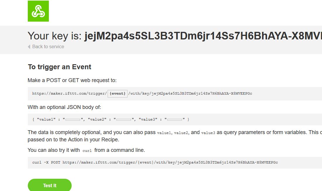
trigger to Maker Webhook
ESP to IFTTT:
    #include  <ESP8266WiFi.h>
    #include  <arduino.h>
    #include "DataToMaker.h"

    #define SERIAL_DEBUG // Uncomment this to dissable serial debugging

    // define gpio pins here:
    #define NUMBER_OF_SENSORS 1 // THIS MUST MATCH THE NUMBER OF SENSORS IN THE SENSOR ARRAY / NO MORE THAN 3


    #define GARAGE_DOOR_PIN 4 // GPIO2 (D4)
    // pin for heatbeat LED
    #define HEARTBEAT_PIN 13 //GPIO13


    // Define program constants

    const char* myKey = "mykey"; // your maker key here
    const char* ssid = "Chacha"; // your router ssid here
    const char* password = "mypassword"; // your router password here

    // define program values
    int sensors[NUMBER_OF_SENSORS] = {GARAGE_DOOR_PIN}; // place your defined sensors in the curly braces
    String doorStates[2] = {"Closed", "Open"}; // You can change the LOW / HIGH state strings here


    // declare new maker event with the name "ESP"
    DataToMaker event(myKey, "ESP");

    // LEAVE SET

    int pvsValues[NUMBER_OF_SENSORS];
    bool connectedToWiFI = false;

    void setup()
    {
    #ifdef SERIAL_DEBUG
      Serial.begin(115200);
      delay(200);
      Serial.println();
    #endif

      delay(10); // short delay
      pinMode(HEARTBEAT_PIN, OUTPUT);
      for (int i = 0 ; i < NUMBER_OF_SENSORS ; i++)
      {
        pinMode(sensors[i], INPUT);
        pvsValues[i] = -1; // initialise previous values to -1 to force initial output
      }
      WiFi.mode(WIFI_STA);
      ConnectWifi();
    }

    void loop() {
      if (wifiConnected)
      {
        if (DetectChange())
        {
          debugln("connecting...");
          if (event.connect())
          {
            debugln("Connected To Maker");
            event.post();
          }
          else debugln("Failed To Connect To Maker!");
        }
        delay(1000); // pause for 1 second
        digitalWrite(HEARTBEAT_PIN, !digitalRead(HEARTBEAT_PIN));
      }
      else
      {
        delay(60 * 1000); // 1 minute delay before trying to re connect
        ConnectWifi();
      }
    }

    bool ConnectWifi()
    {
      // Connect to WiFi network
      debugln();
      debugln();
      debug("Connecting to ");
      debugln(ssid);
      unsigned long startTime = millis();
      WiFi.begin(ssid, password);

      while (WiFi.status() != WL_CONNECTED && startTime + 30 * 1000 >= millis()) {
        delay(500);
        debug(".");
      }
      if (WiFi.status() == WL_CONNECTED)
      {
        debugln("");
        debugln("WiFi connected");
      }
      else
      {
        WiFi.disconnect();
        debugln("");
        debugln("WiFi Timed Out!");
      }
    }

    bool wifiConnected()
    {
      return WiFi.status() == WL_CONNECTED;
    }


    bool DetectChange()
    {
      int val;
      bool changed = false;
      for (int i = 0 ; i < NUMBER_OF_SENSORS ; i++)
      {
        if ((val = digitalRead(sensors[i])) != pvsValues[i])
        {
          pvsValues[i] = val;
          event.setValue(i + 1, doorStates[val]);
          debug("Changes Detected On Value");
          debugln(String(i + 1));
          changed = true;
        }
      }
      if (!changed) debugln("No Changes Detected");
      return changed;
    }


    void debug(String message)
    {
    #ifdef SERIAL_DEBUG
      Serial.print(message);
    #endif
    }

    void debugln(String message)
    {
    #ifdef SERIAL_DEBUG
      Serial.println(message);
    #endif
    }

    void debugln()
    {
    #ifdef SERIAL_DEBUG
      Serial.println();
    #endif
    }
Those sketches are calling ESP8266.h, the details of this library are here
additional ESP boards
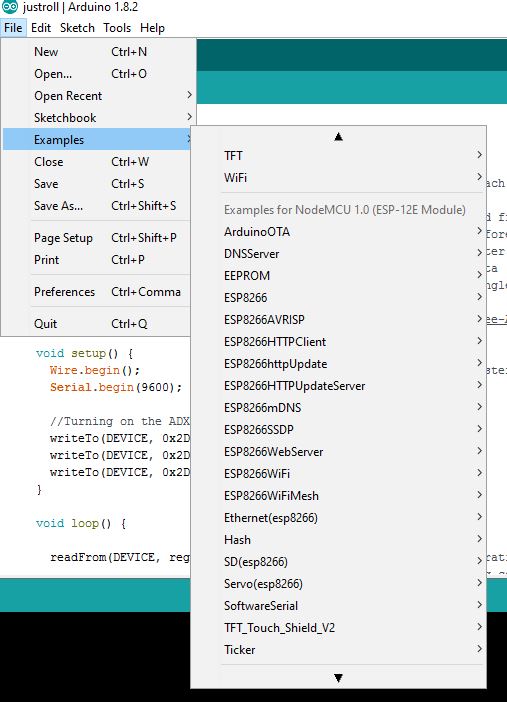
ESP examples
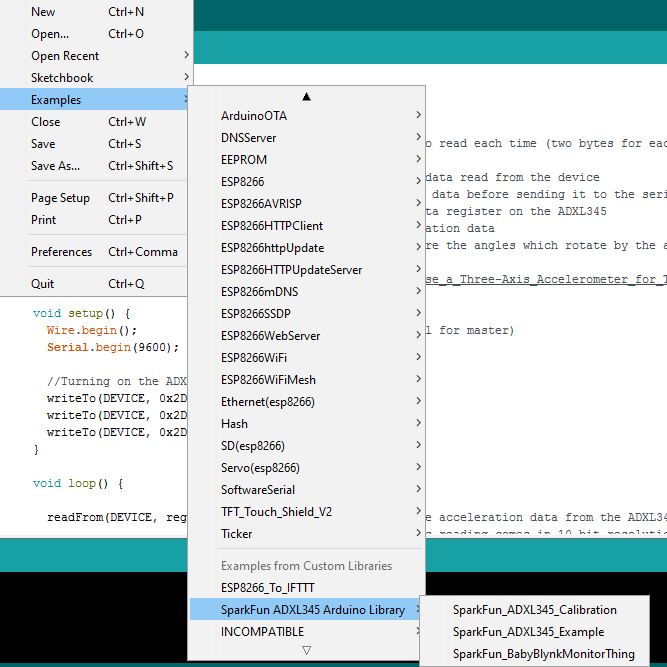
Github ESP-IFTTT examples
IFTTT is quite simple to use but not that straightforward. Once you got an account in IFTTT, add the Maker Webhook to your aps. This makes possible to connection of DIY project to the platform.
Create a new applet I noticed it doesn't work well on Firefox and is confused by tactile screens. Applets need to be turned on by sliding a button and this can only be done using the screen.
The working communication:
As a next step I would like to bypass IFTTT.
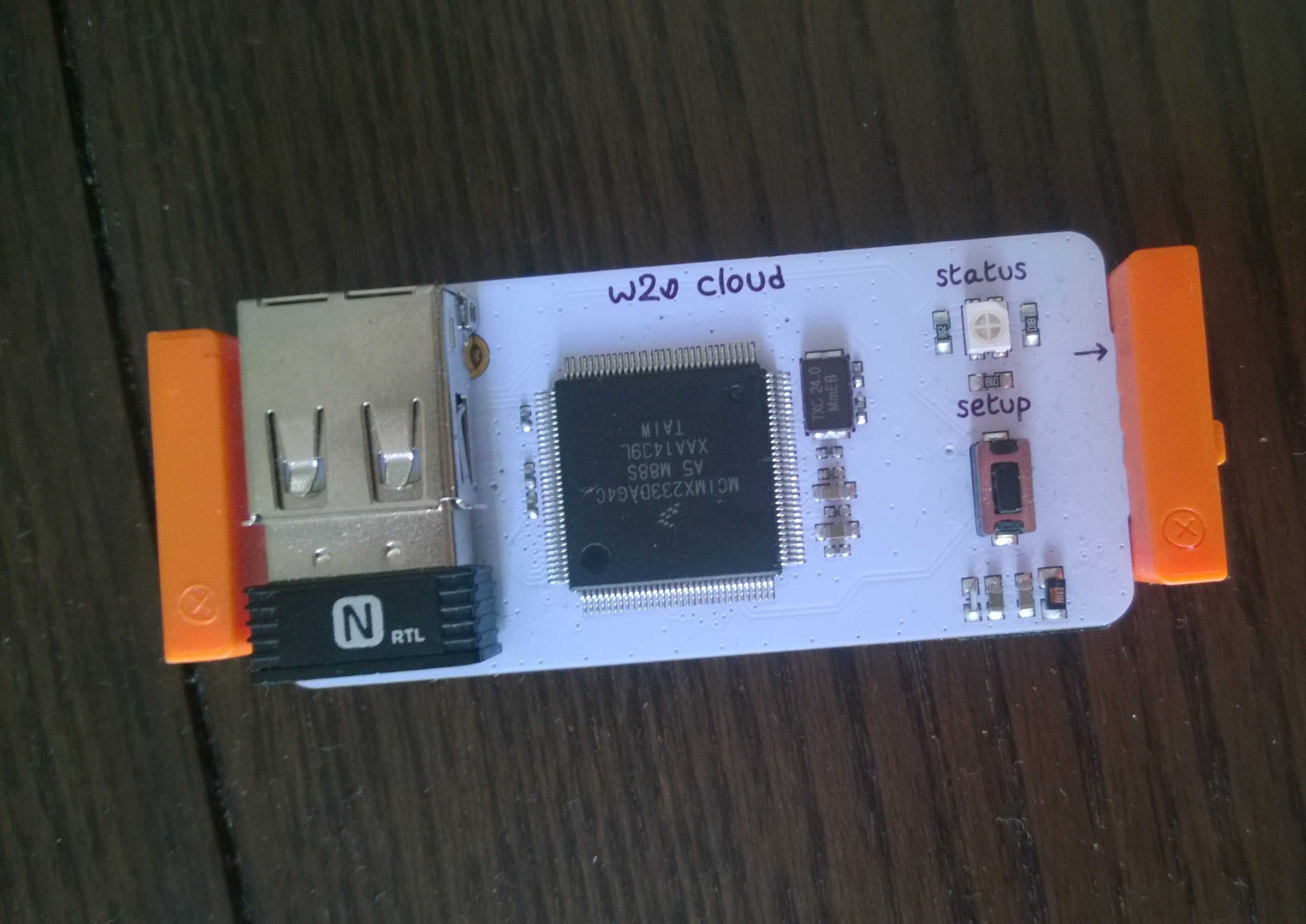
Cloudbit

opensource and Littlebit
IFTTT Maker Webhook
As my final project involves transmission of signals thanks to energy harvesting, this week was quite crucial. I first considered the use of LoRa communication but Wifi is now an option as the ESP can work with 3V. I am keen on little PCB so serial and I2C communication can help building a lighter, more distributed, nervous system for my final project at the image of octupus brains. As I would like to a wireless system, I need to investigate further the powering of a branched system.
Regional review
General remark, we are less and less at the regional reviews. We were only 3 this week.
Yassine seemed to have mastered this project with 2 well soldered satchakit communicationg through I2C, he also used a logic analyser. I will reread his page.
Denis did a remarkable comparative table of the communication protocols. He also tested I2C with Satchakit, added timestamp convertor to it.
I got several suggestion to make my project work:
- Try loading sketches into Satchakits with a Mac.
- Increase the offset number in fabmodule for generating .rml.
- I designed an ESP board with no voltage regulator as we did not big 3.3V regulator.
We discussed the possibility of using small ones but Emma didn't push for it as ESP consumes a lot and is likely to heat up.
David drew his Arduino-like board -with a lot of resistot bridges.
Writing those lines I think it would be valuable to sumarize the review sessions and having our pages pointing on interesting topics covered by others.
General review
- 206: Tested Bluetooth, project on mobile laser cutter (safety class reminder)
- 158: Cimatic mirror (to define the body frequency to use)
Oscilloscope use is advised.
- 206: Tested Bluetooth, project on mobile laser cutter (safety class reminder)
- 158: Cimatic mirror (to define the body frequency to use)
Oscilloscope use is advised.