Abstract
This week was about learning to mold and cast a small object
Some of the question raised were:
- What are the constraints imposed by milling the mold?
- Which casting material to use for which purpose?
I mainly used 1 workflow:
Fusion 360 > Modela > VPanel for SRM-20
My biggest achievement: How the design catches the light
My biggest struggle: Finding a design idea
Missing material
| Ventilating system | Masks relevant for chemicals |
Chronology
| Thursday | Friday | Saturday | Monday | Tuesday |
|---|---|---|---|---|
| Demo | Personal design | Milling -finish | Documentation | Frames |
| Group test | Milling -rough path | Silicon | Plaster | Plaster |
Setup
| Softwares | Fonction |
|---|---|
| Modela | Path computing for 3d milling |
Skills acquired
Asssesment validation
Ideation
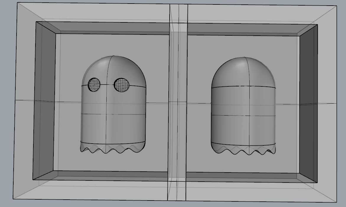
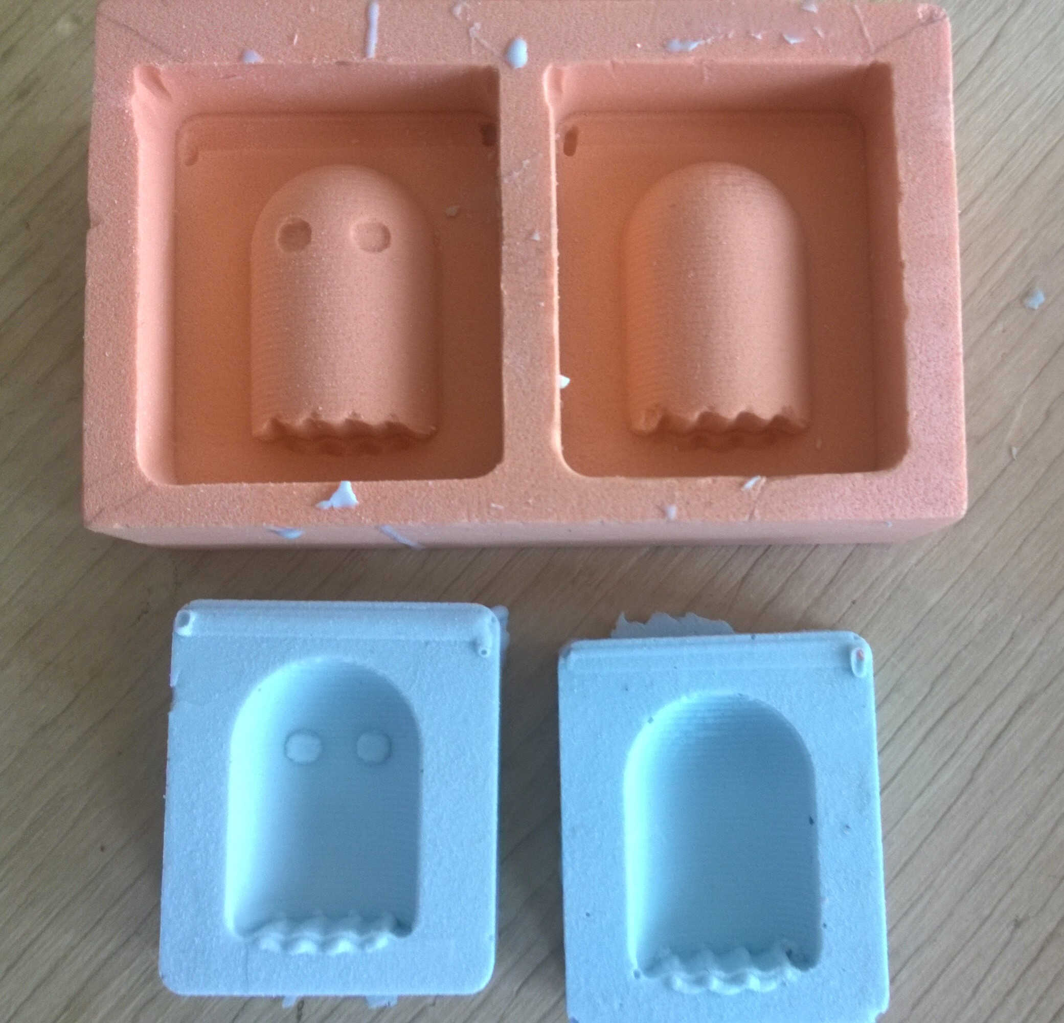
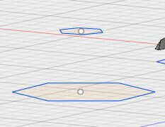
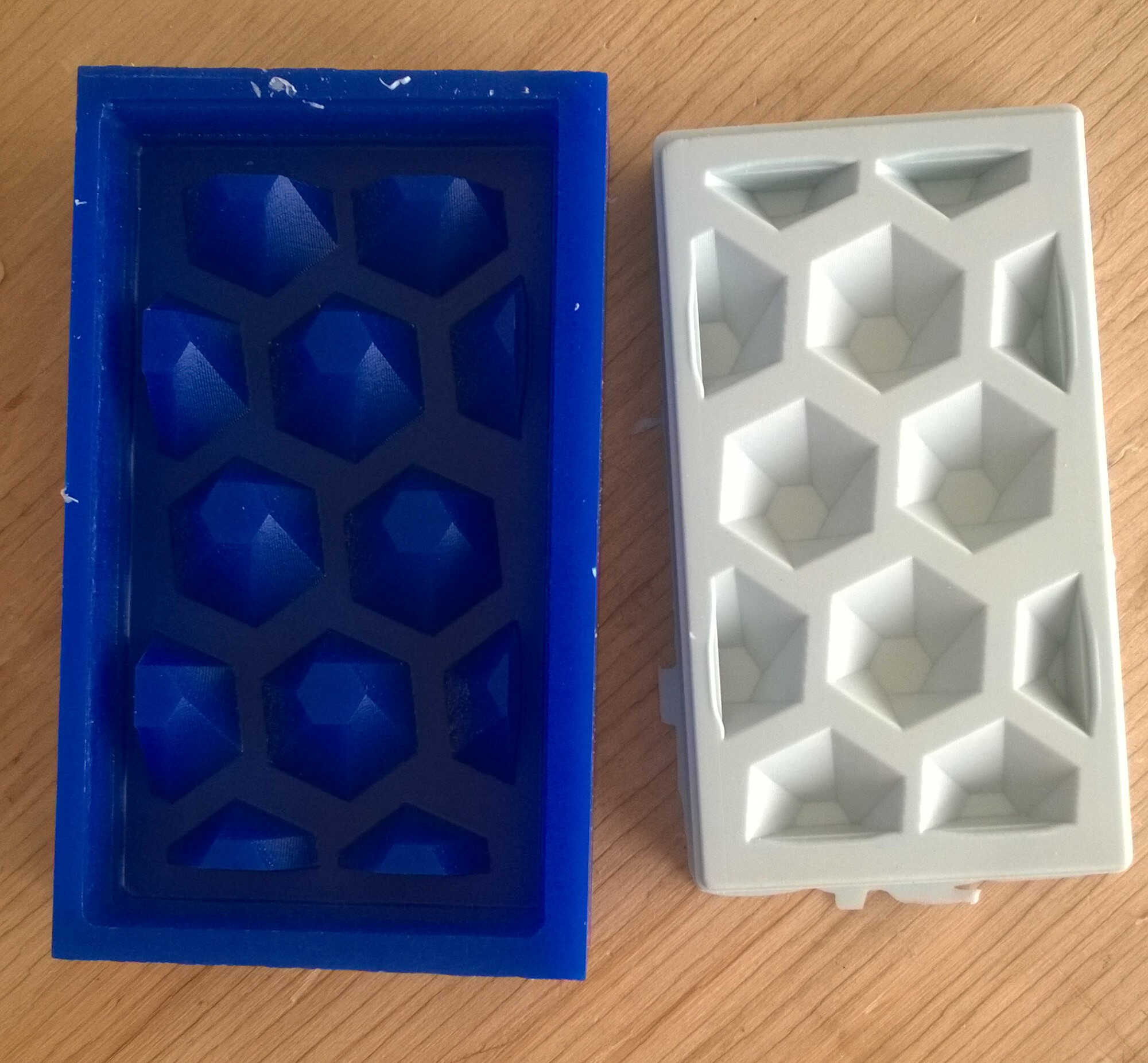
With Yassine we decided to do a test to better understand the whole process on the test brick provided. We considered building a foosball figure so we could build a foosball table with the unused shafts from the machine project. Then we went for a Pacman character but we had some doubts about milling its eyes. Finally we designed a ghost, still inspired from Pacman.
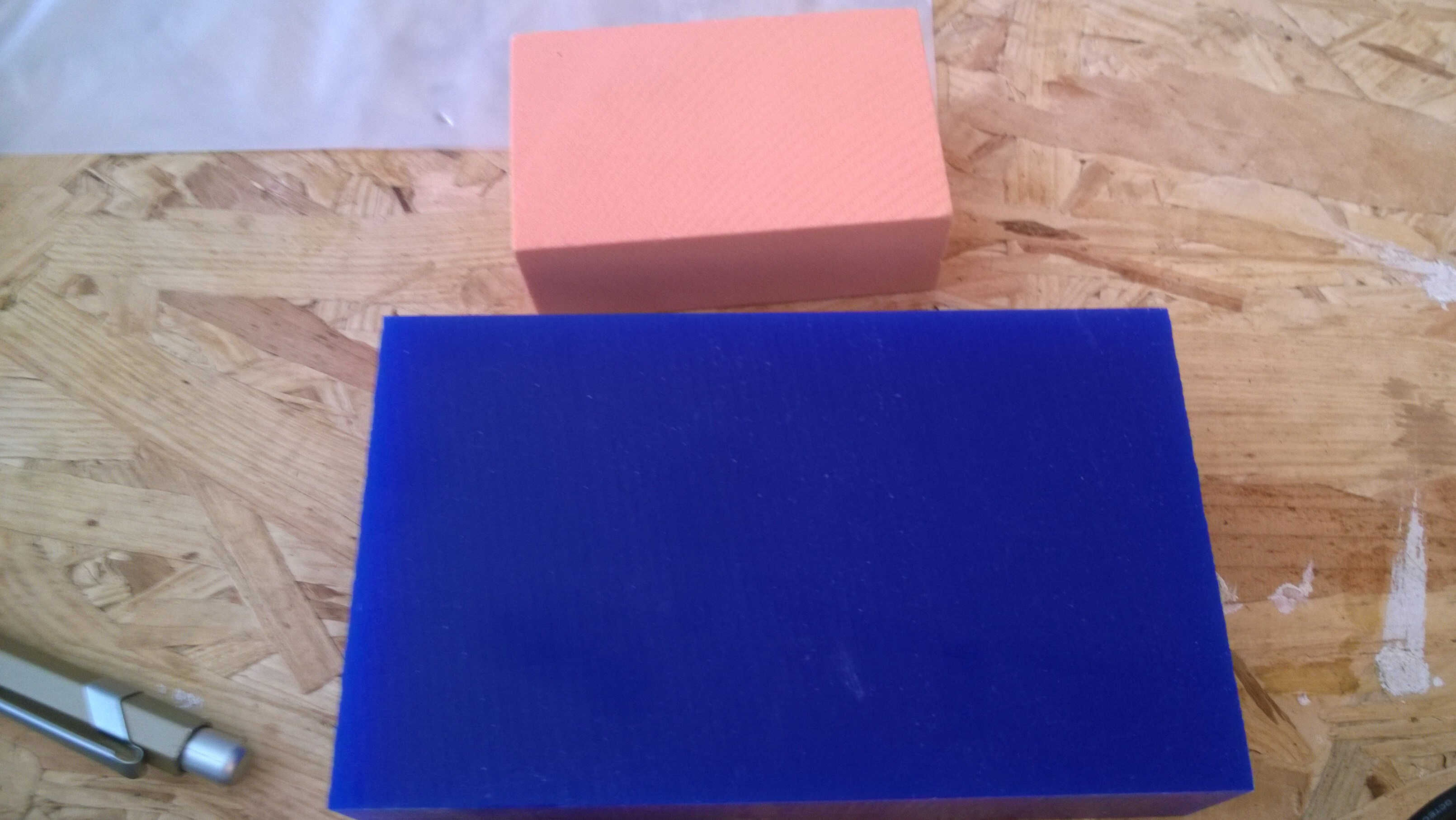
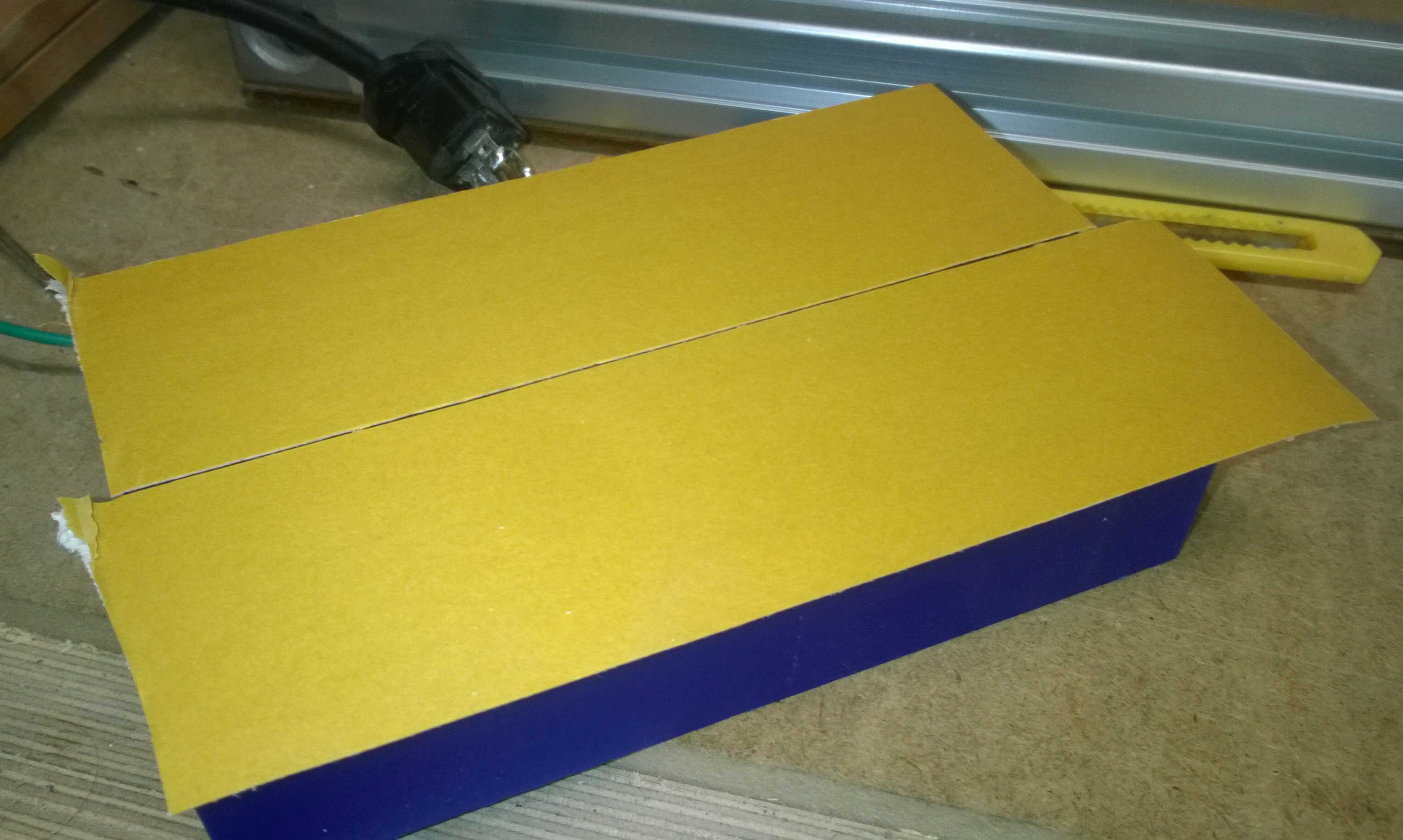
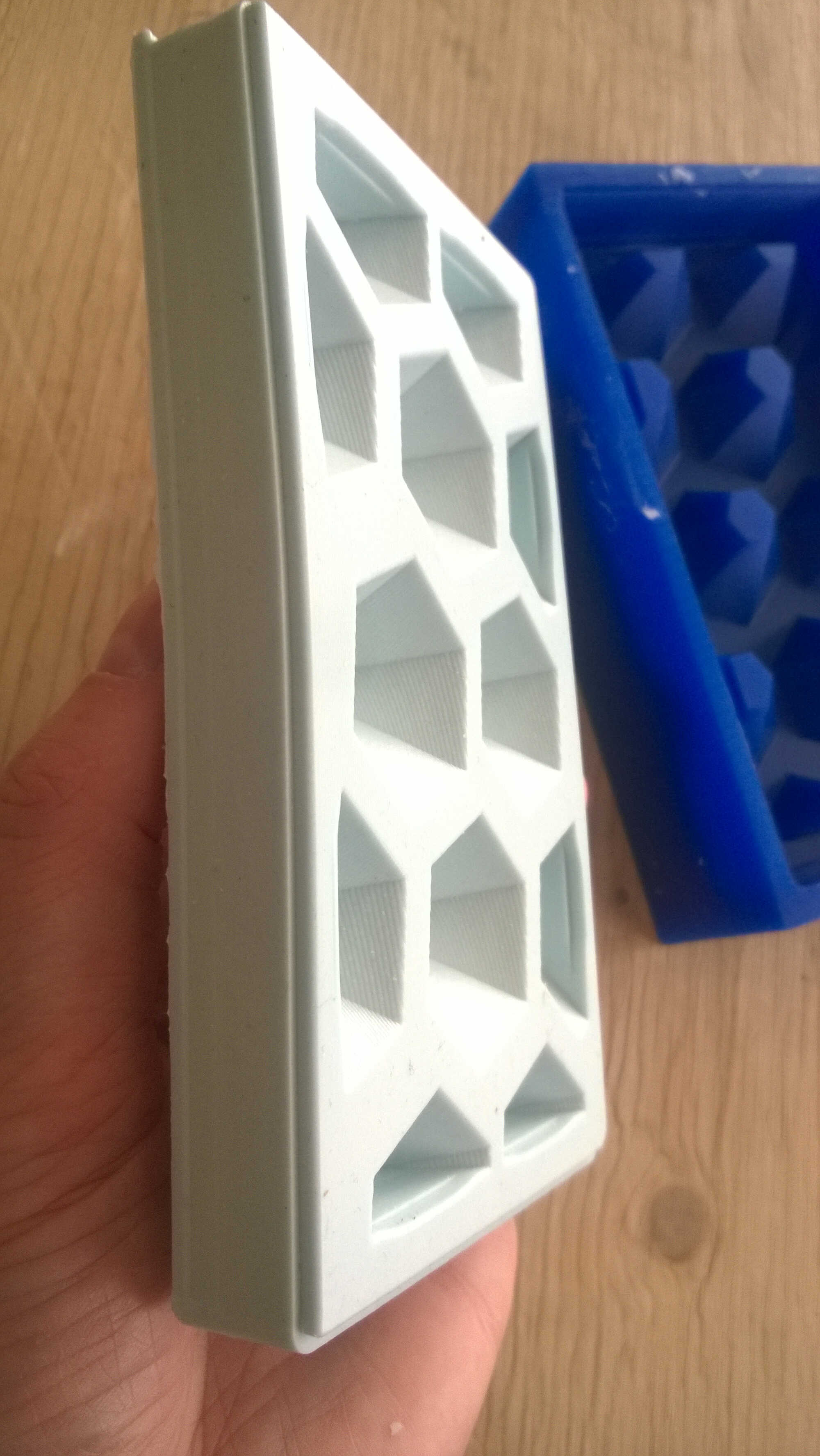
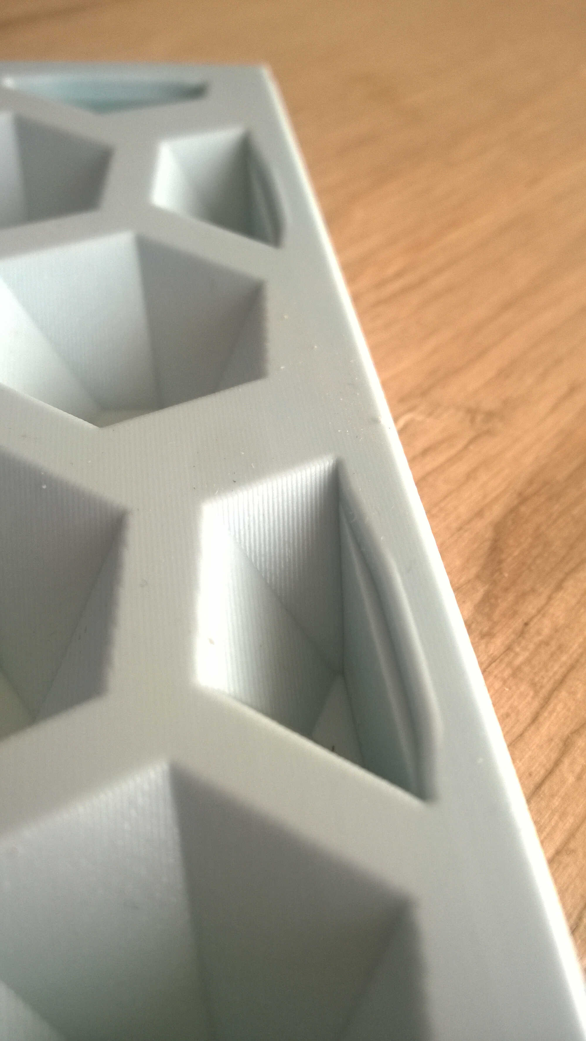
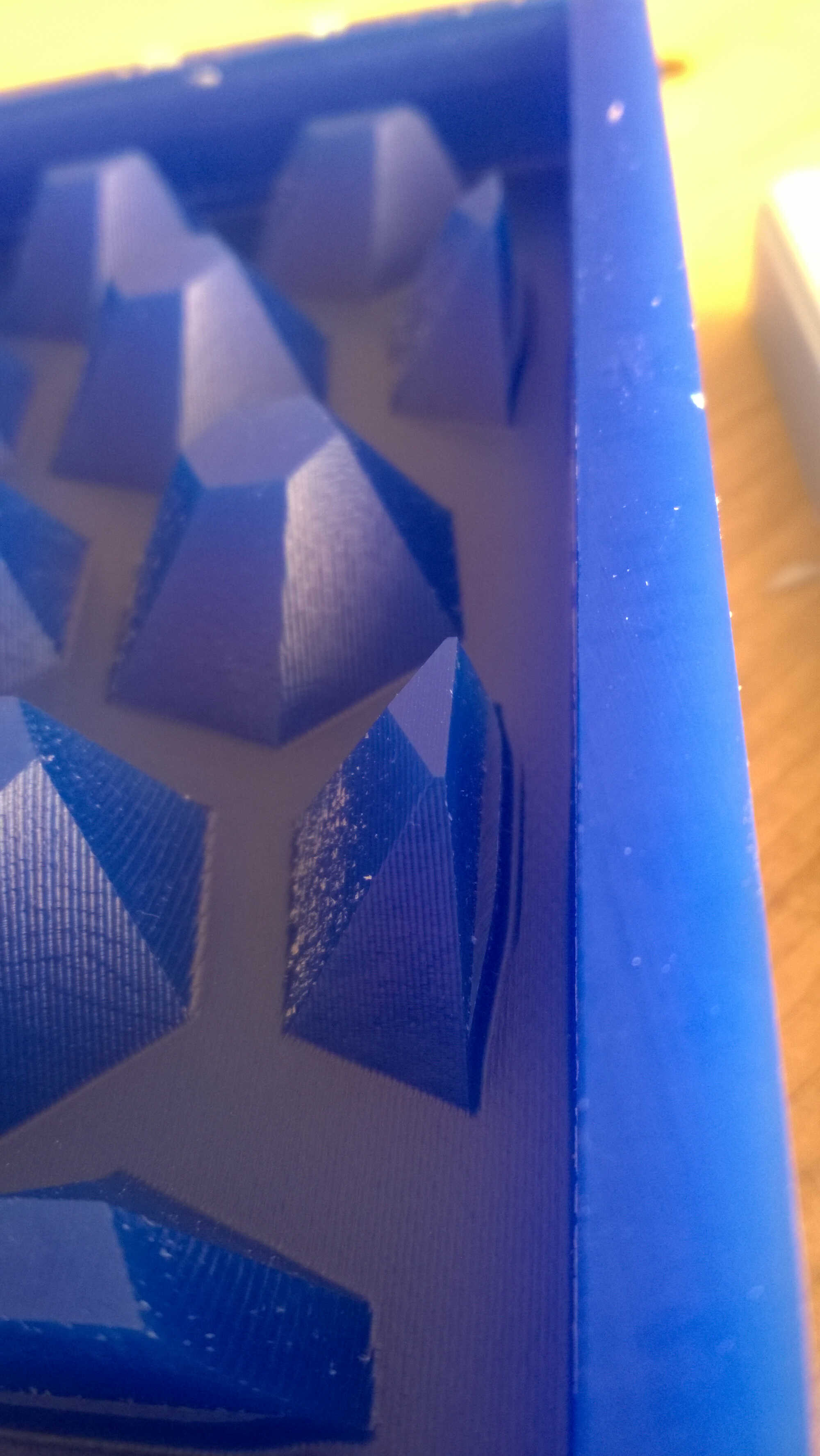
molding materials (blue: wax, orange: Sanmodur)
Designing
Yassine did the model with Rhino/Grasshopper. The main steps of this modelling were the following:
- Modeling a sphere
- Building the "skirt" by extruding the mid-area from the sphere.
- Drawing an ondulated spline curve the width of the skirt.
- Extruding this spline and cutting the "skirt" with it
- Building eyes thanks to Grasshopper
- Building keys for double-sided casting
- Checking the milling bit access
- Renouncing to double-sided casting because the keys took too much space on the small test molding material
double sided ghost Rhino
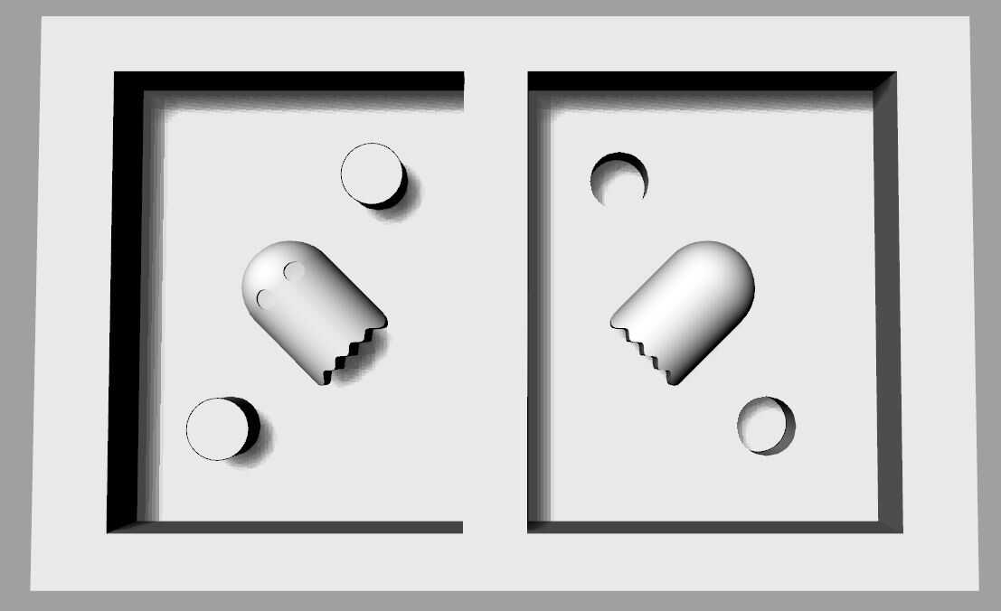
with registration keys
Source file to load here
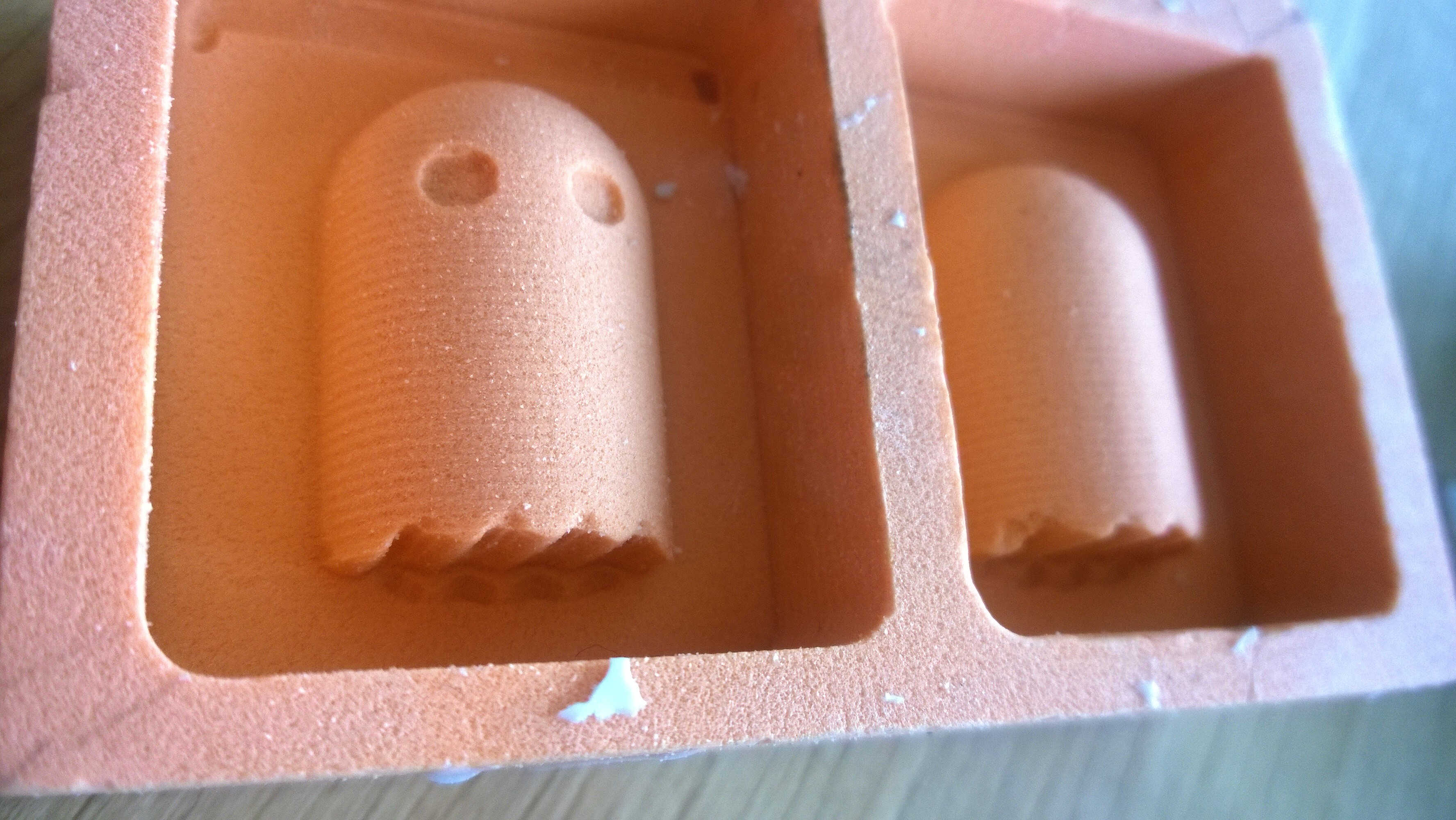
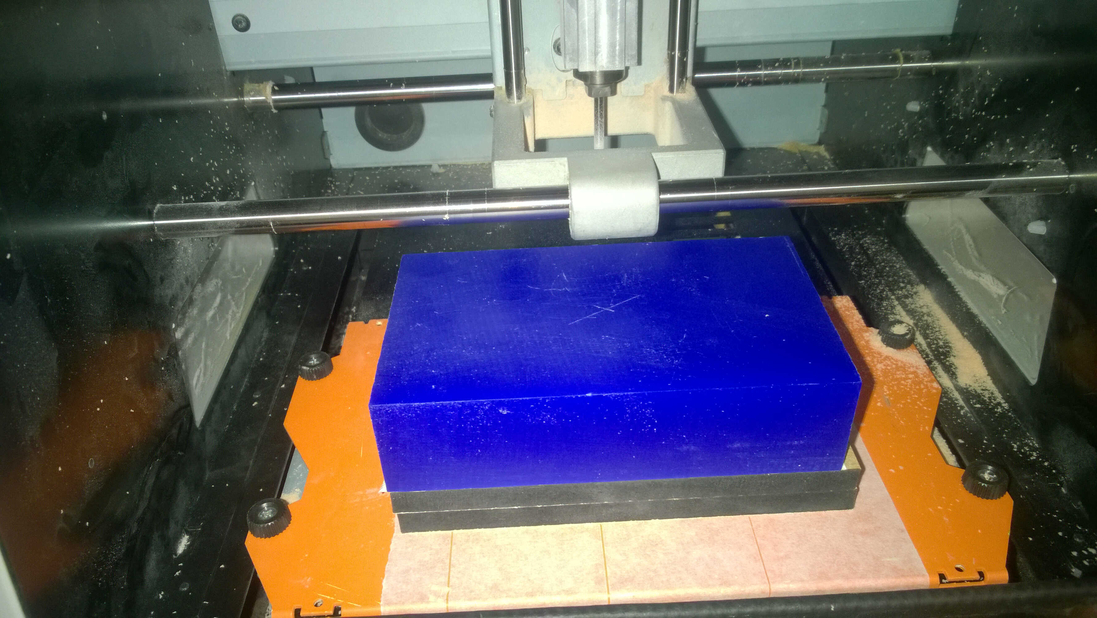
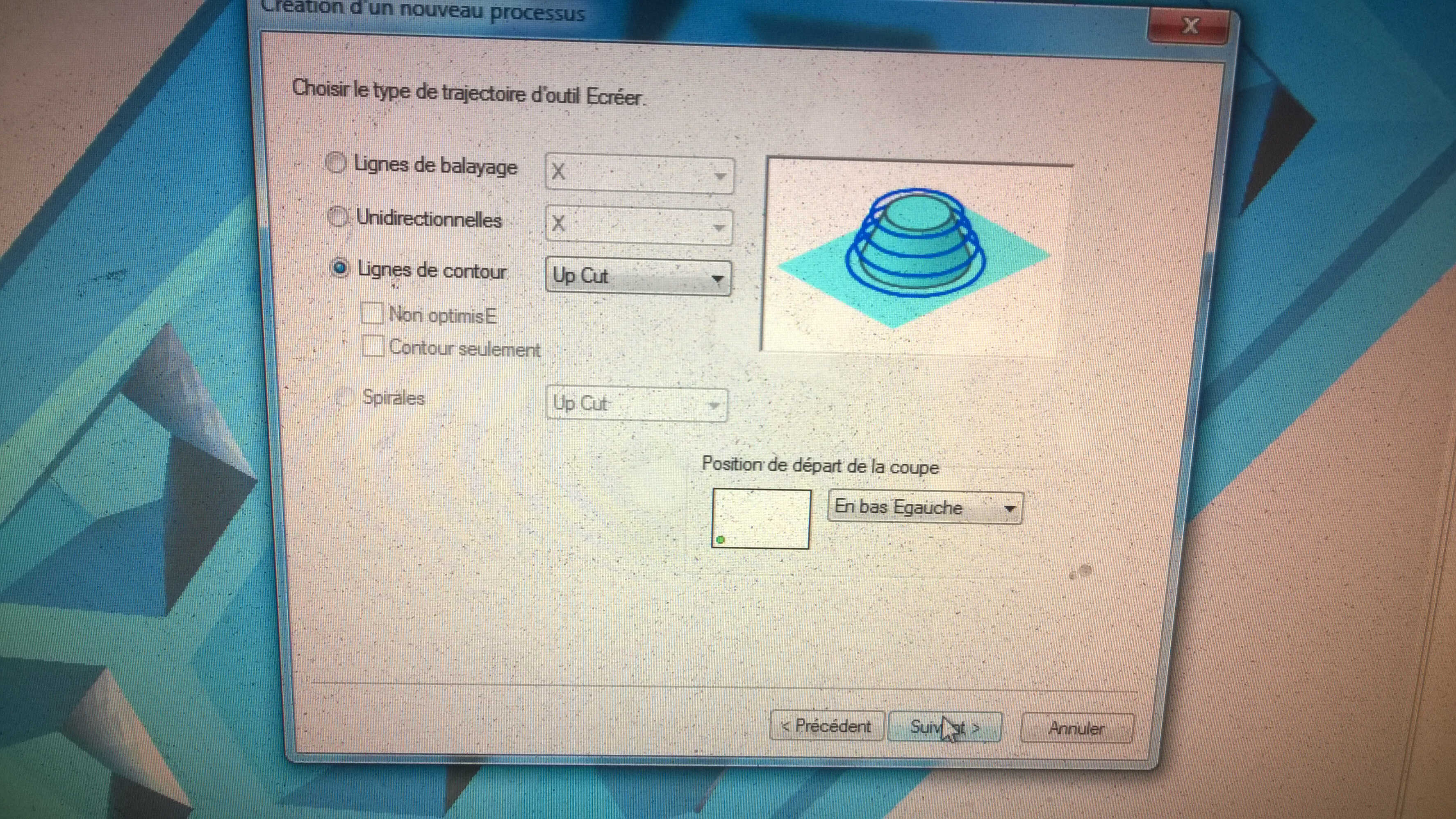
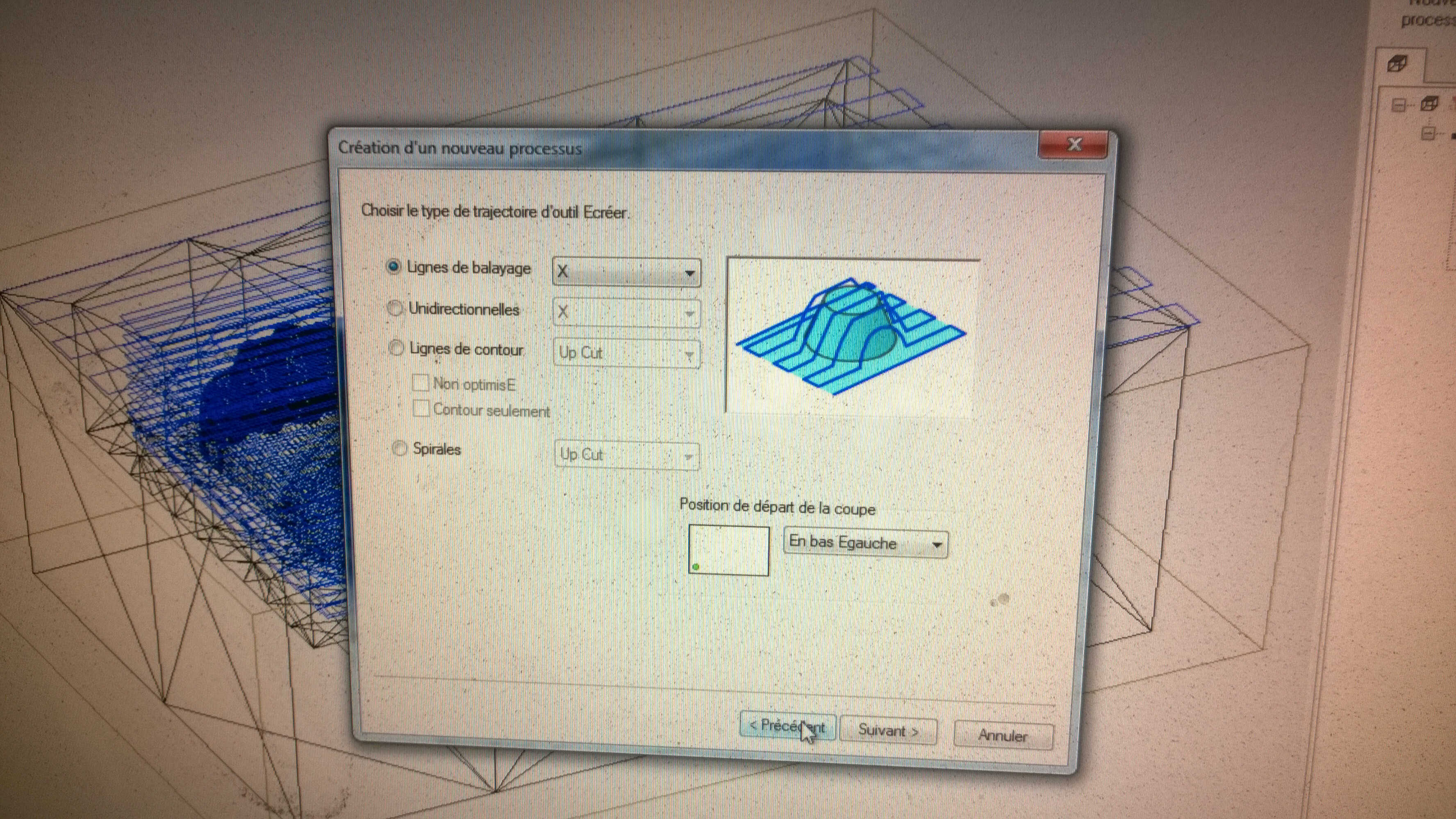
Milling
We then proceeded to the milling.
- Imported the stl in Modela
- Defined a new process: rough path
- Fitting the milling 5.65 mm flat tip with its chuck
- Defined the origins: XY at the center of the brick and the Z with a paper as usual in VPanel
- Launched the milling through Modela (bottom right icon)
- End of the rough path
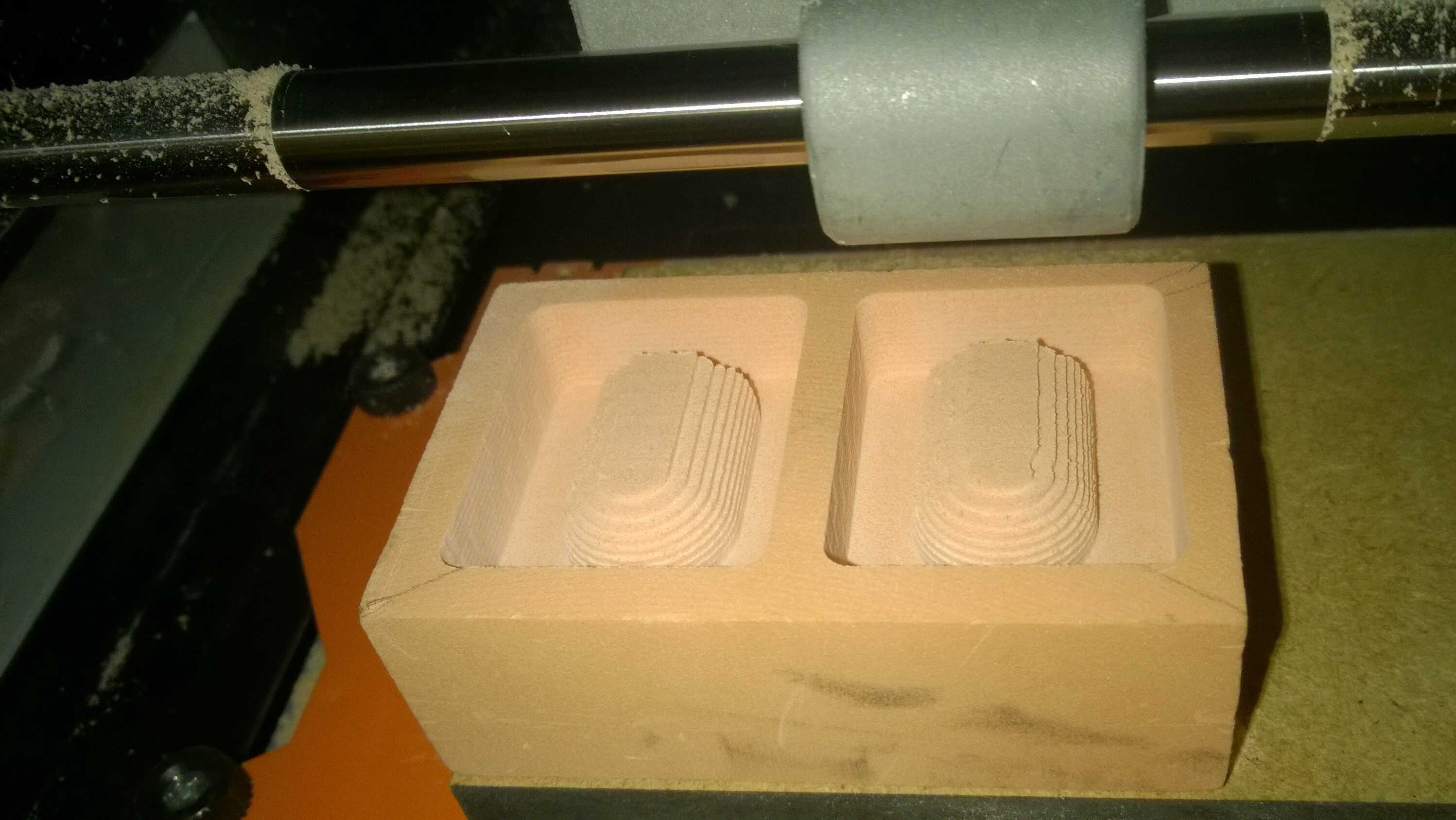
- Changed the milling bit to 1.5mm rounded tip
- Defined the finish parameters (defined the same area as in the rough path thanks to capture, slowed down speed to 20 mm)
- Defined the Z
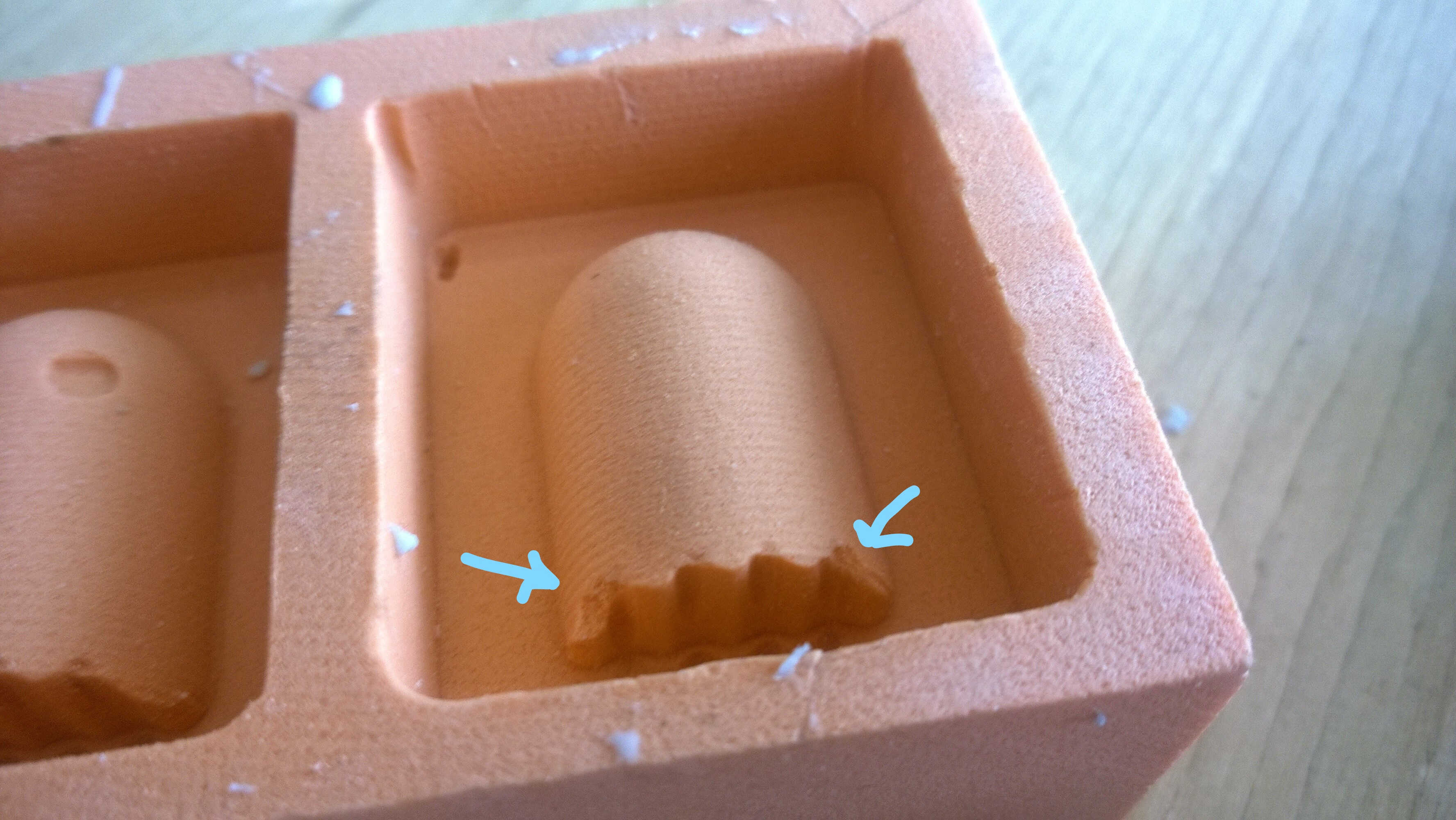
- Launched the milling and realized the bit was hitting the walls
- Canceled the milling and redefined the milling area (each pocket was finish separetely)
Stl imported
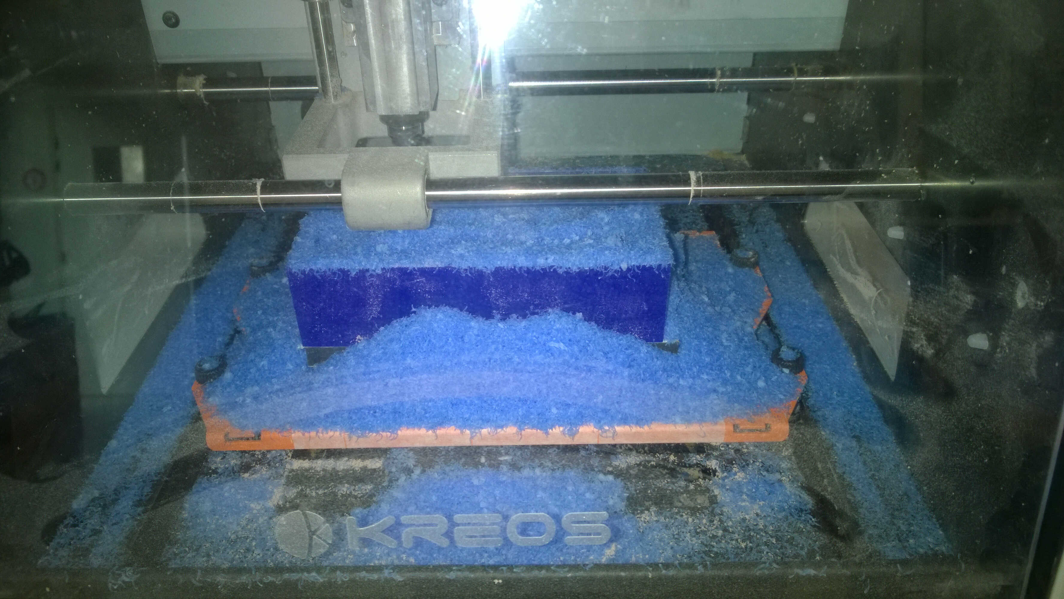
rough path
sand texture
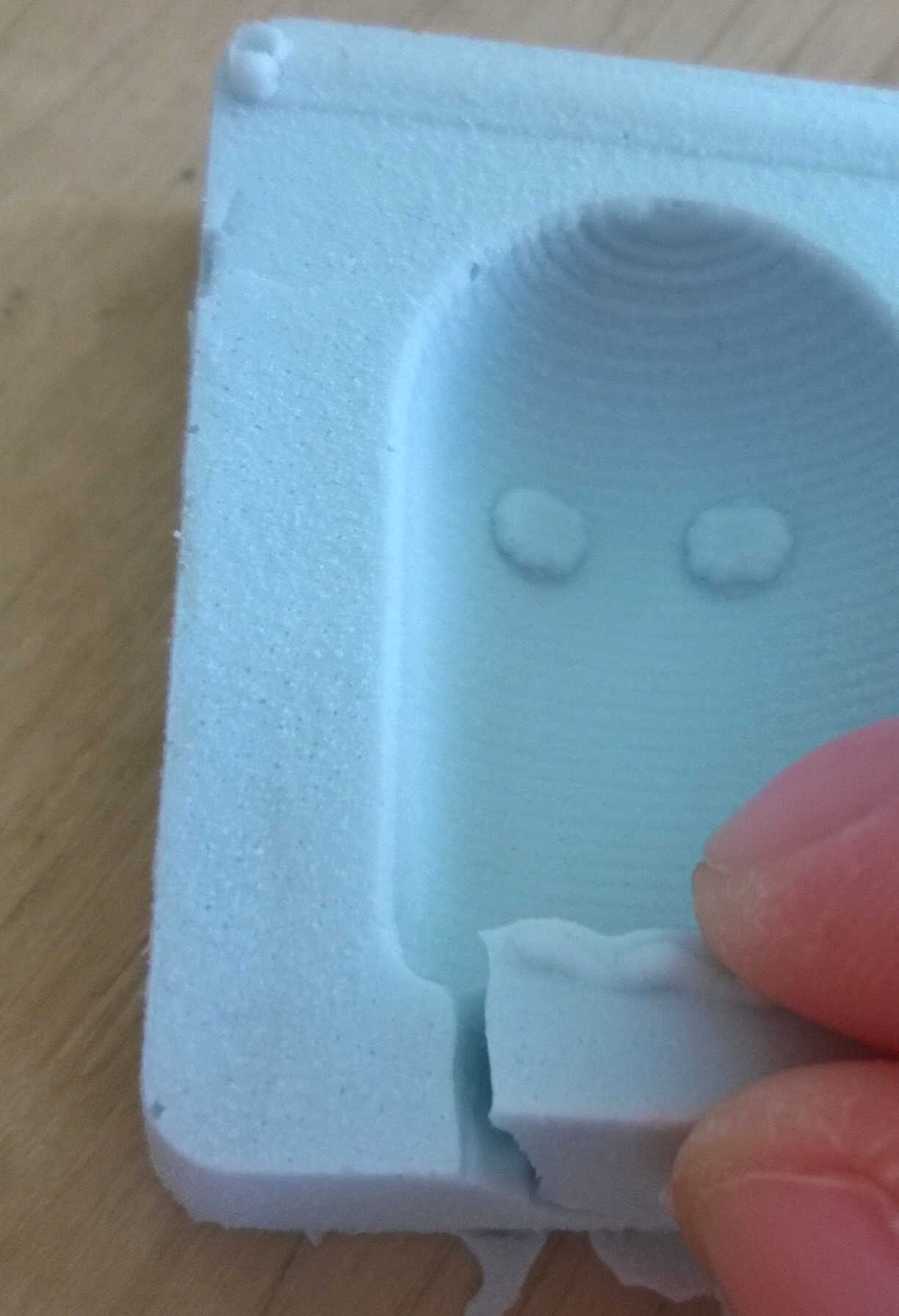
Casting silicon
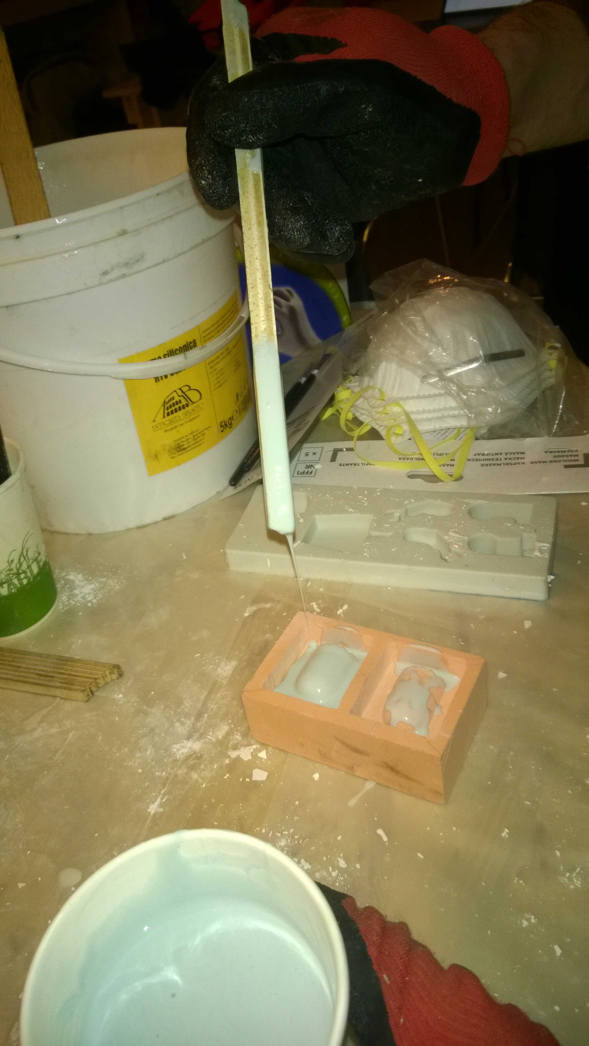
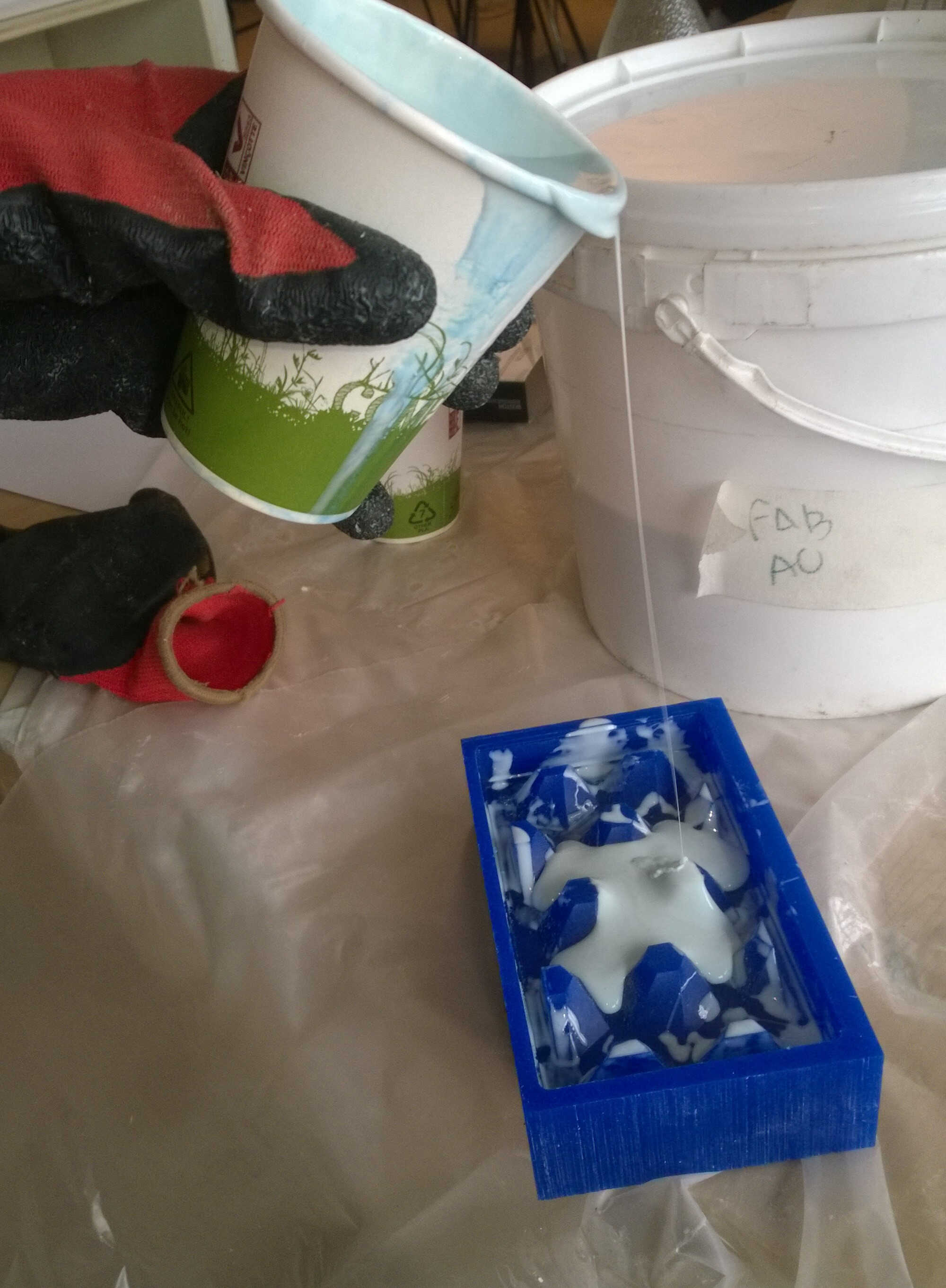
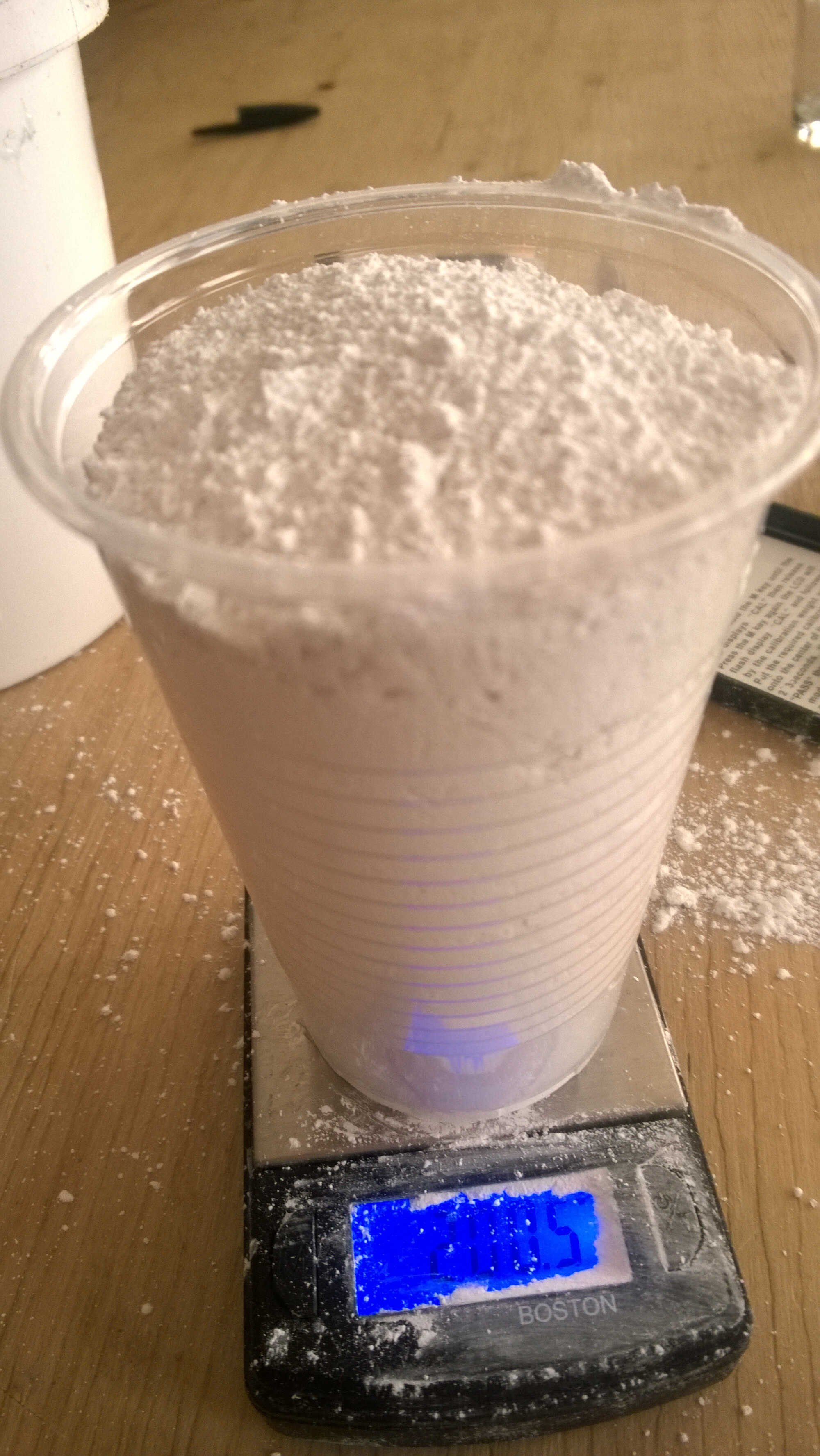
Once the mold cleaned we prepared the silicon.
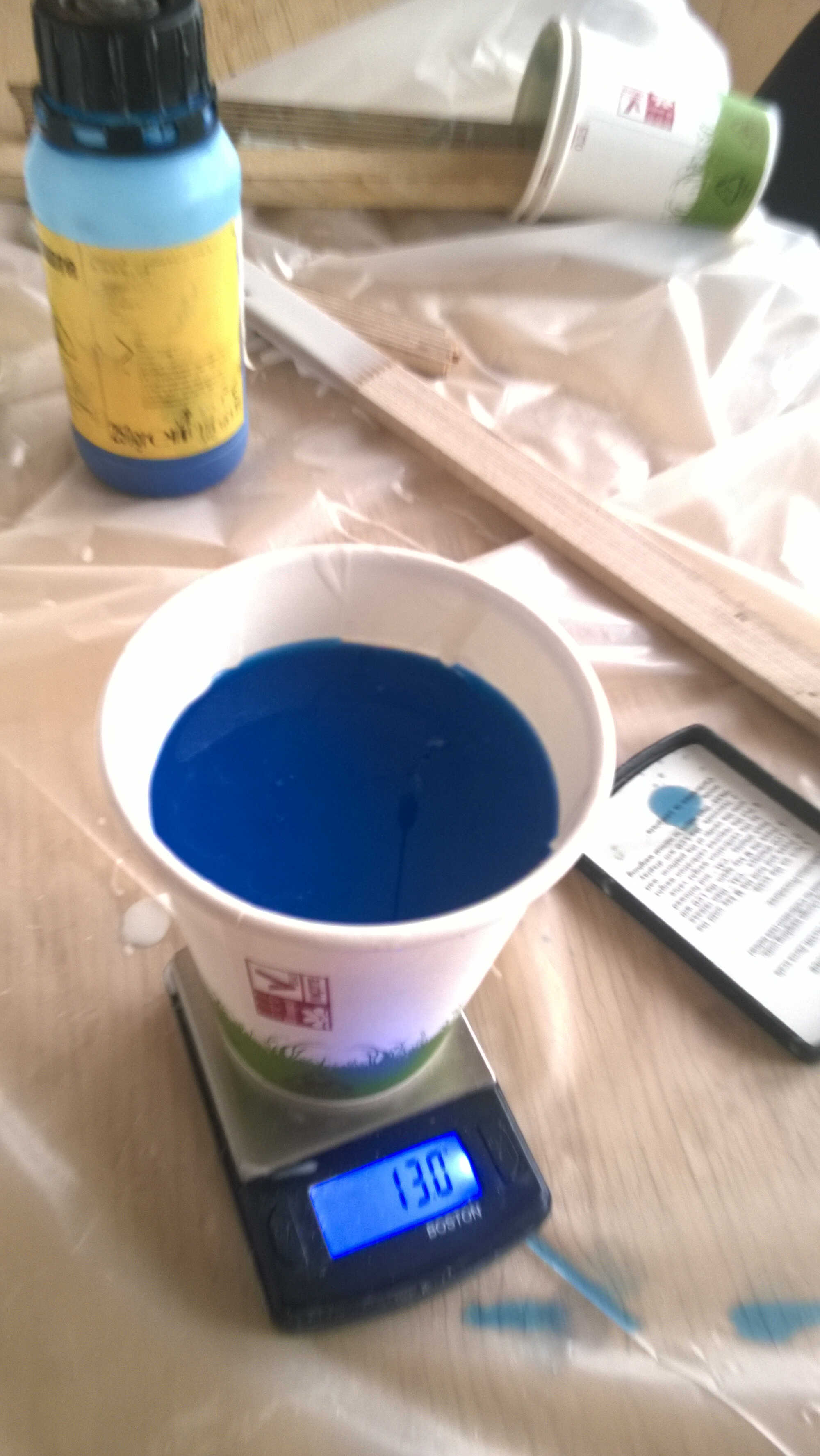
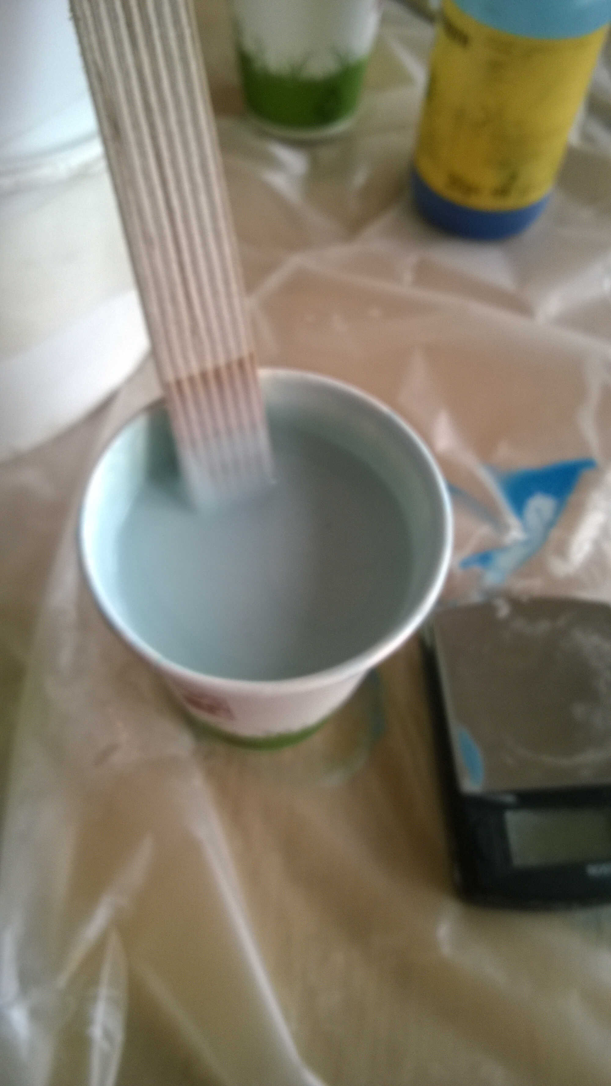
- Slowly stirred the silicon with a wood stick
- Filled a paper cup with silicon
- Weighted the cup
- Added 5% by weight of the hardening agent
- Stirred gently to homogenize
- Made a pouring spout with the paper cup
- Used a brush to apply silicon at the places of the mold difficult to access
- Poured the mix from a height into the lowest part of the mold
- Filled the mold
- Let it set for 24h
silicon
demolding
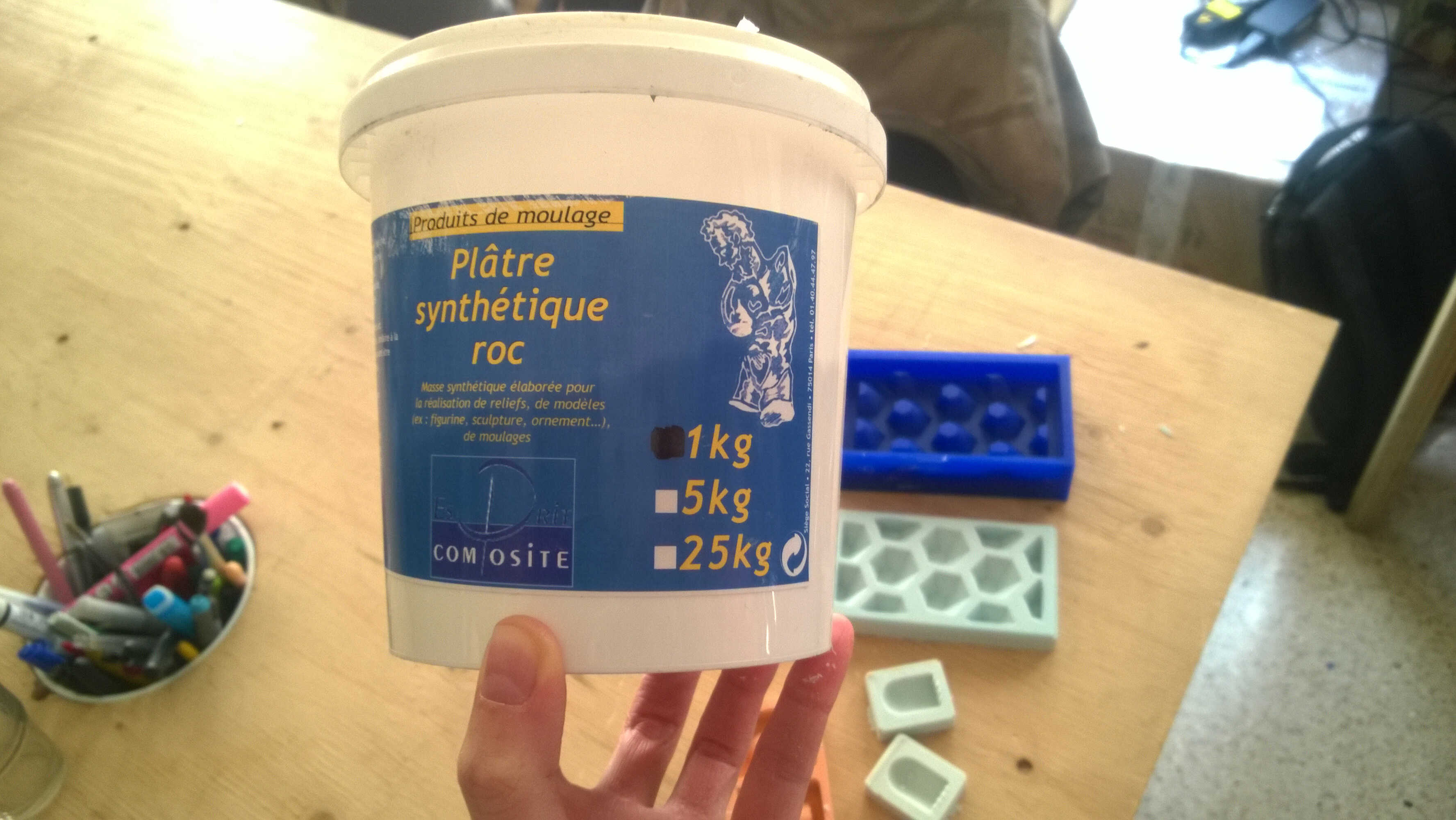
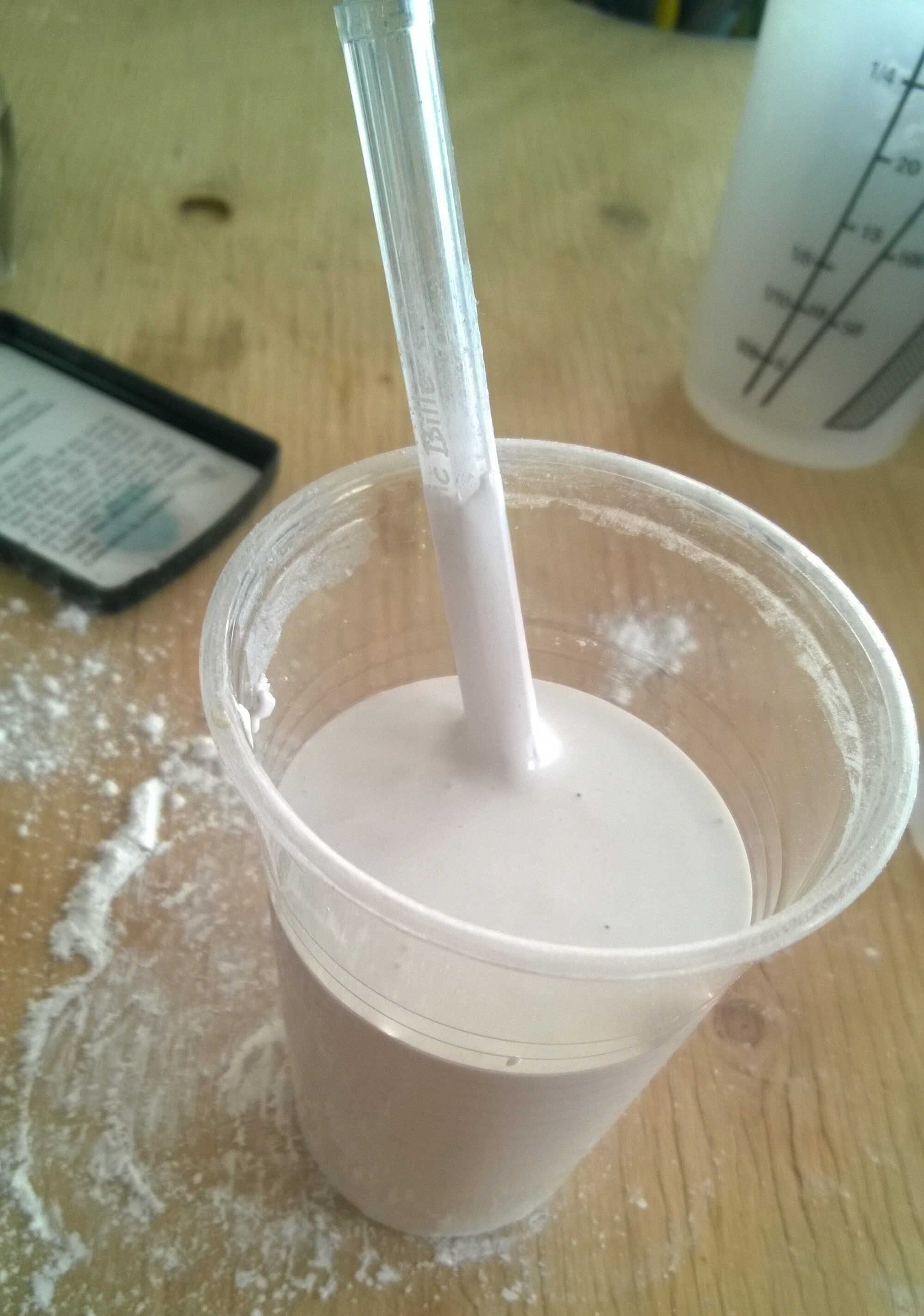
Casting synthetic plaster
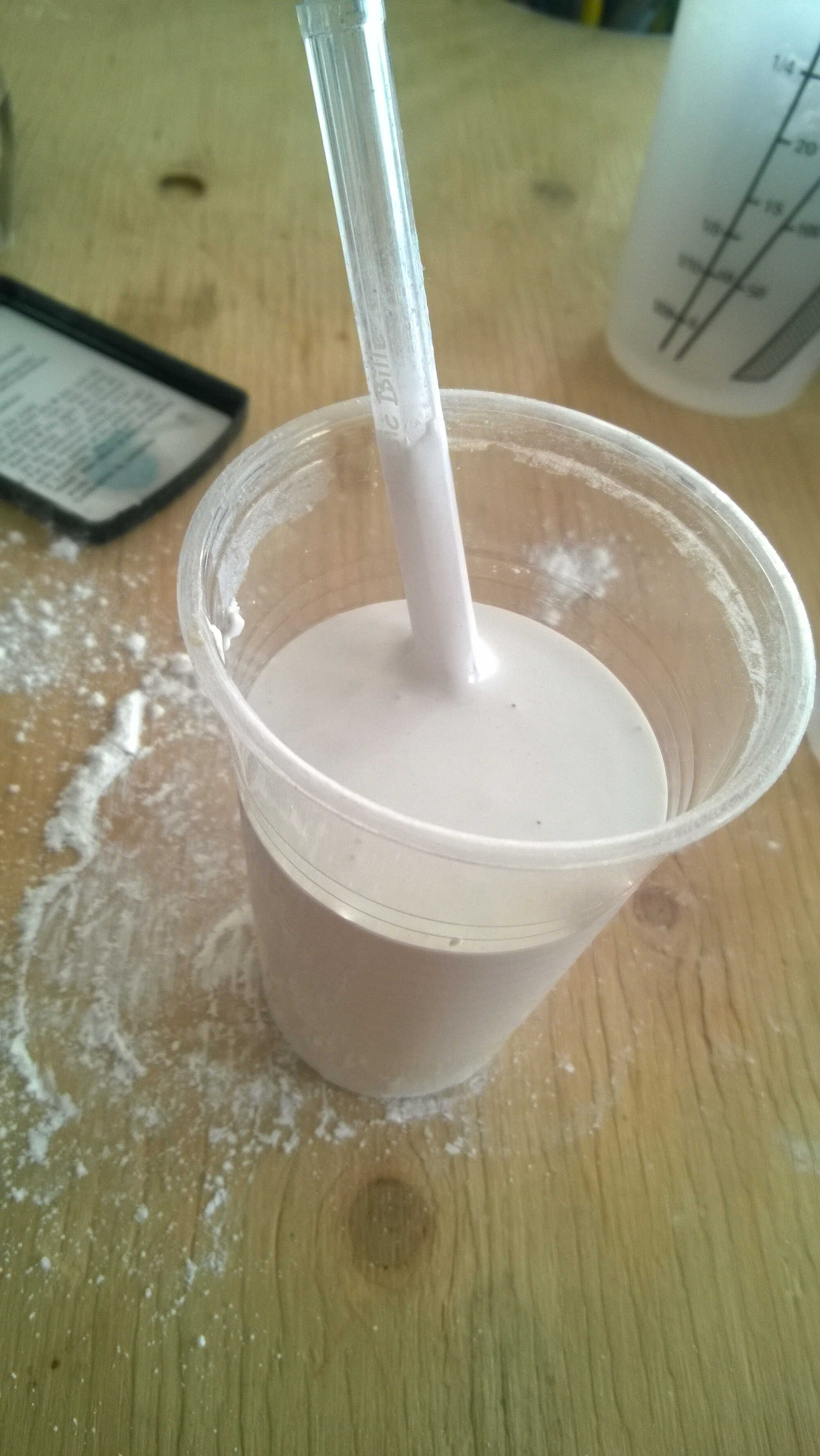
Once silicon demolded, plaster was prepared
- 200g of plaster for 5cl water (progressively adding plaster powder and mixing a bit like when making pancake)
- Pouring from a height to prevent bubbles
- Set in 15 mn
product used
mixing
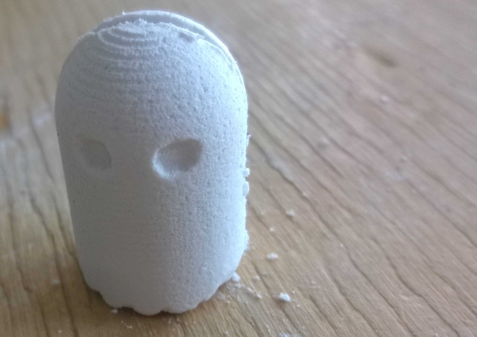
plaster ghost
Lessons learned
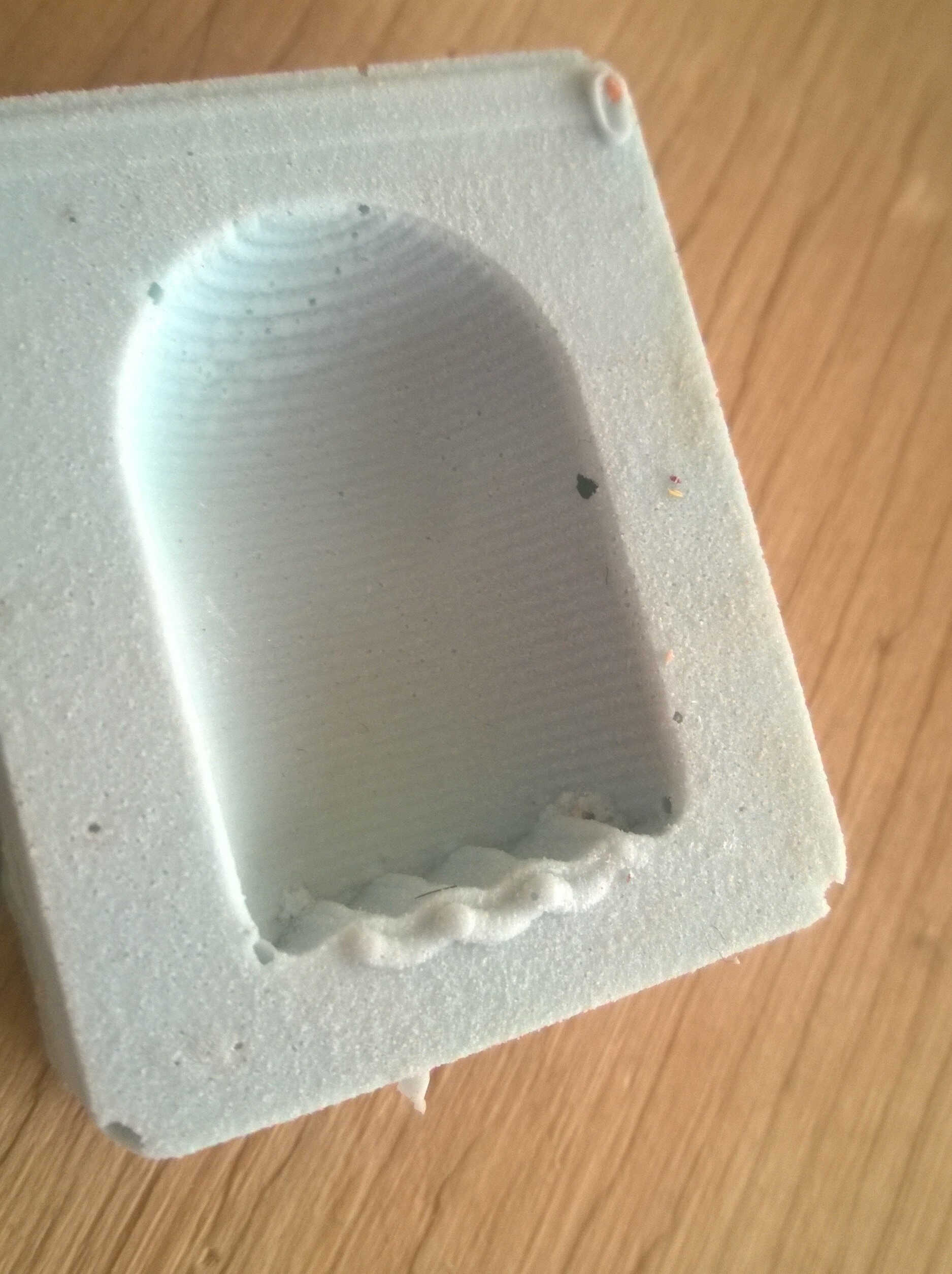
- Try not to have a thin silicon wall somewhere in the model, it might not come off
torn silicon
- Best to use fingers than tools to remove silicon from the wax, it limits the risks of tearing
- Sanmodur is quite delicate, a piece was removed with silicon
snatched Sanmodur
- Plaster is also quite delicate and requires a certain thickness to resist demolding
- Under the fine ondulation of the skirt the mold was engraved deeper, this might have resulted in demolding issue
engraving
- Silicon hardener is actually an irritant and should be used with good ventilation. We were first told that plaster and silicon molding mixes were harmless.
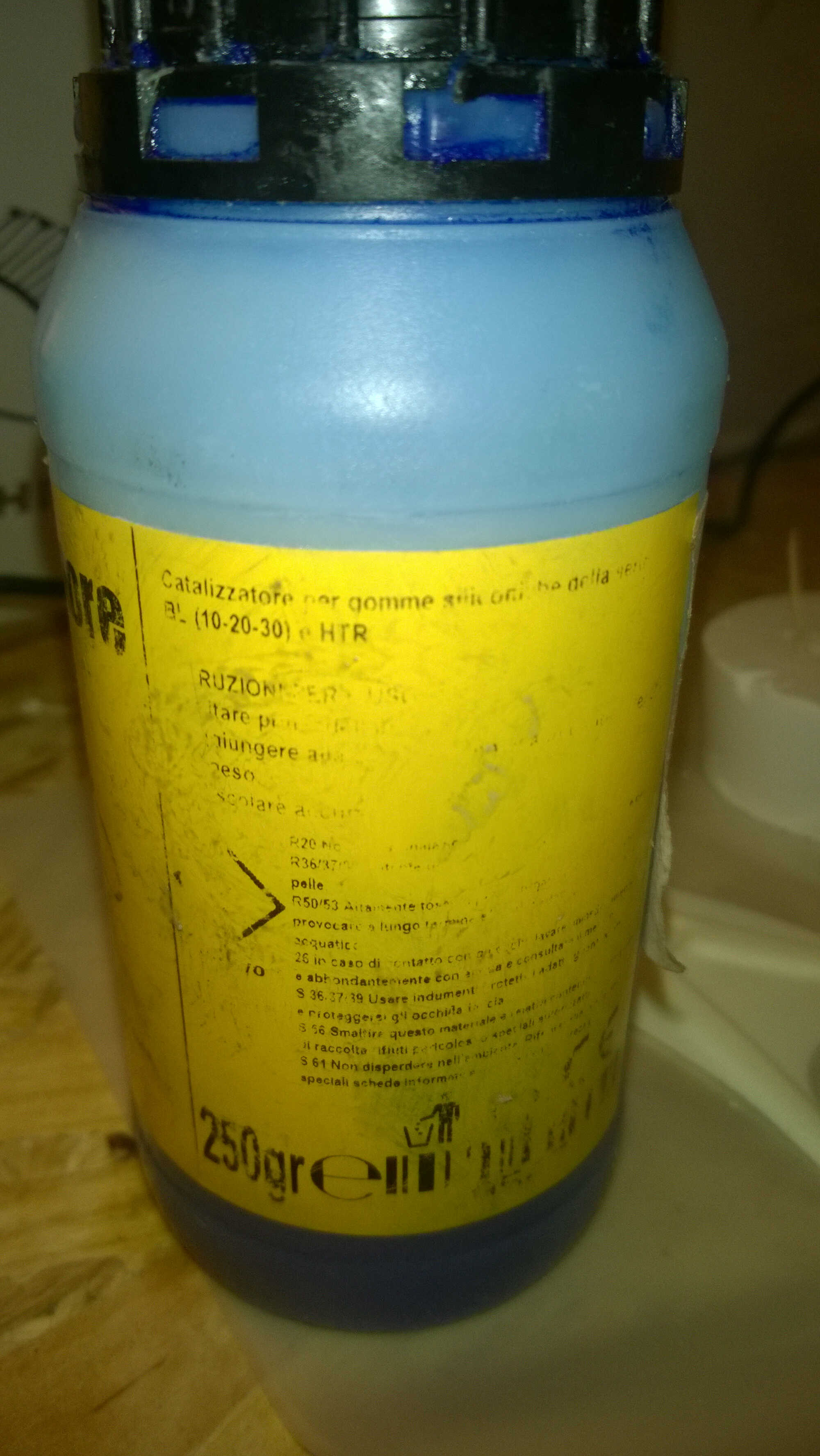
hardener pictogram
Ideation
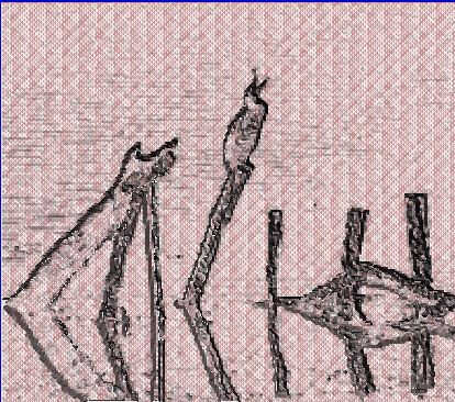
The same struggle than with Yassine started. The little time devoted to design was kind of stressful, I consecutively engaged in two dead-ends. First I wanted to convert a picture into stl. Several aps provide the convertors. I tried Embossify. I took what I though an "easy" image of a cormoran and converted it. The result contained to much triangles and i didn't succeed to smooth it (tried with the Make Solid option in MeshMixer). Also some details were too fine for the end mills we are using.

Original picture
resulting stl
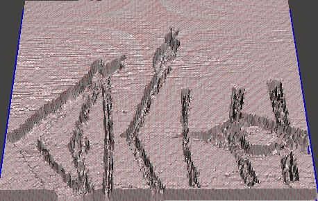
resulting stl inclined
Then I got inspired from what Roman did last year, a topographical mold. I would have liked to mold a place dear to my heart, Edinburgh volcano. This time I tried 2 different solutions Terrain2stl and Terrainator. The first one was not enough refined and the second one, not for free.
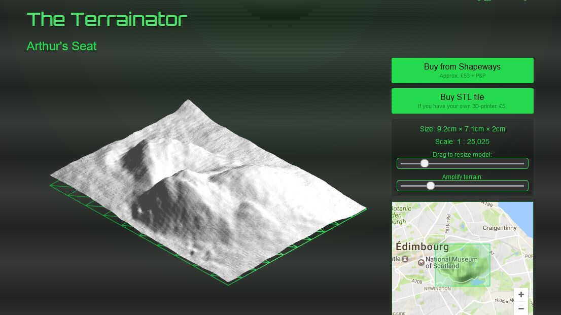
Terrainator result
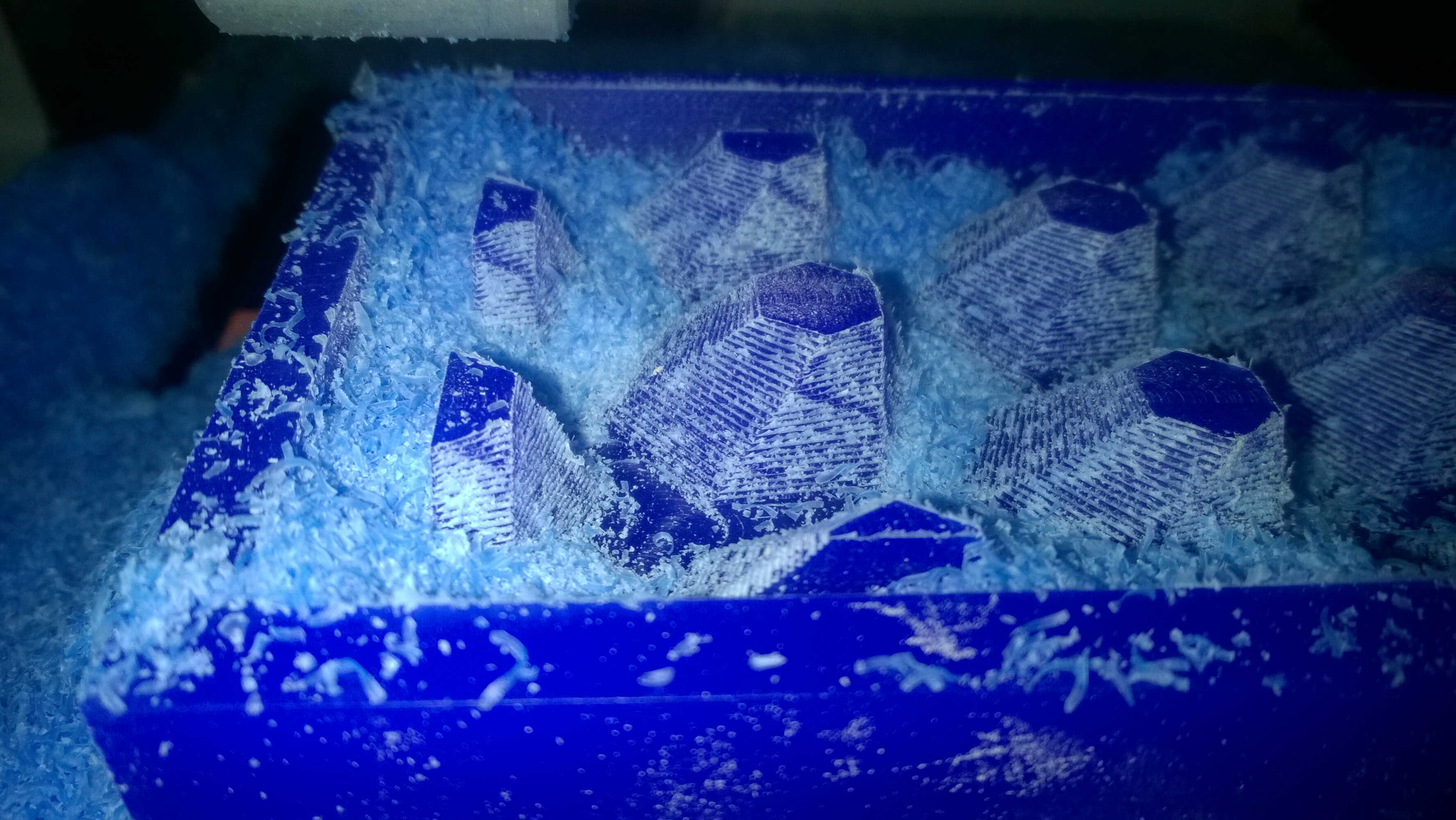
Once again I had to switch idea, I looked at Pinterest for inspiration and found some nice bas-reliefs looking like origami. Knowing that sharp angles might be an issue, I chose to isolate one form and repeat it to form a texture. The form was build in Fusion 360 following those steps, I was trying to reproduce origami bas-relief:
- Inscribed polygon sketch
- Second inscribed polygon sketch
- Displacement of the second polygon above the first one
- Rotation of the second polygon
- Loft between the two polygons
superposed polygons
It looked like an obturator so decided to keep it
- I built a box representing the wax
- I hollowed it on a depth of 15mm by cutting it with another box letting 6 mm walls -I knew wall collapsing might be an issue
- I placed my form in it playing with its height and its scaling
- I placed as many forms in the hole as possible, the one with parts beyond the walls were cut (Displaced > sSketch of a line > Split body with this line extended > Replaced in the hole)
- I let space between the walls and the forms for the milling bit
I was a bit in a rush as Fusion crashed. I should have used the same form cut in half at opposite edges so that the casts could be assembled.
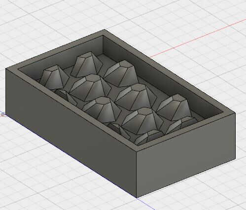
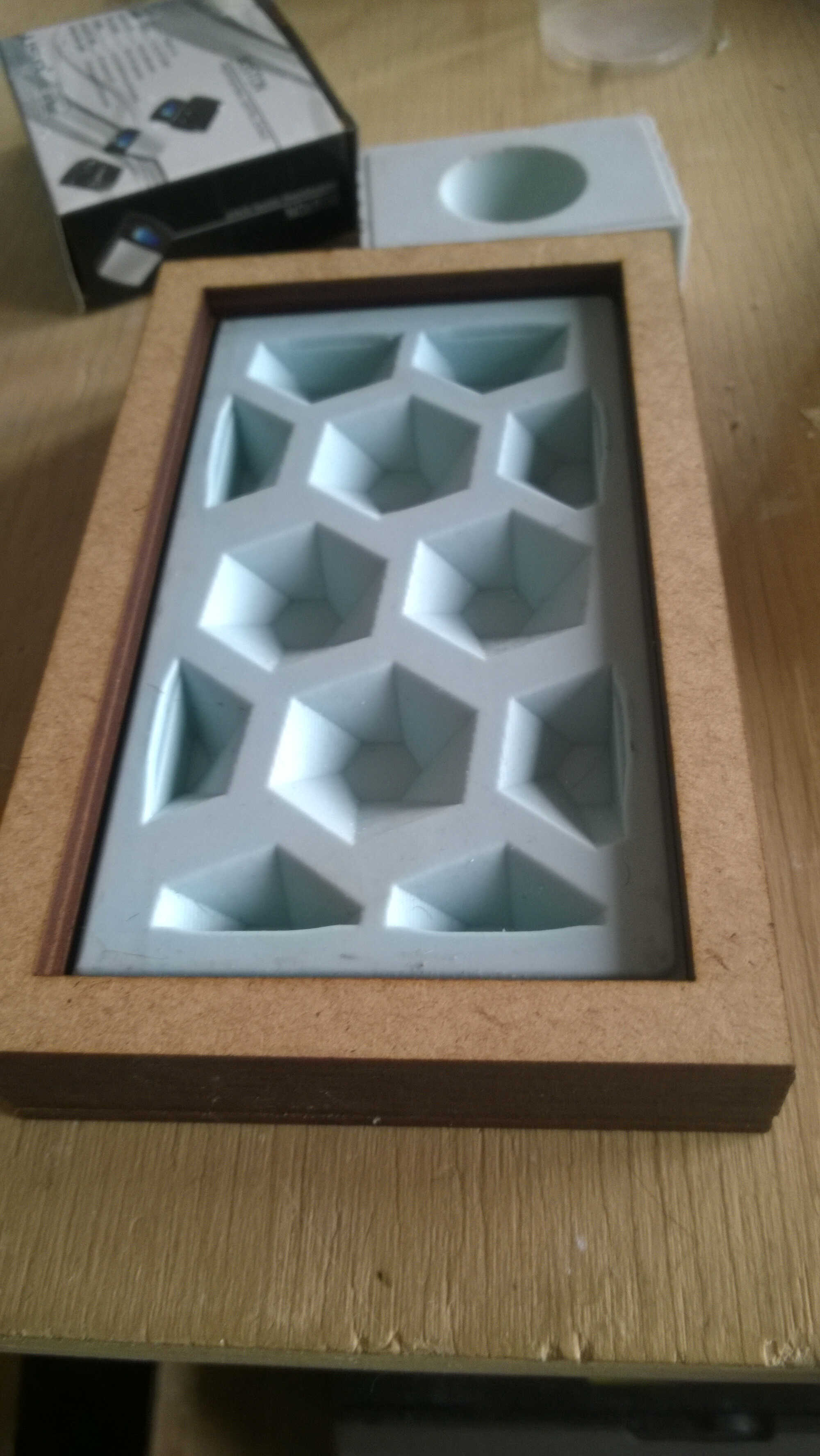
mold-elization
Source file to load here
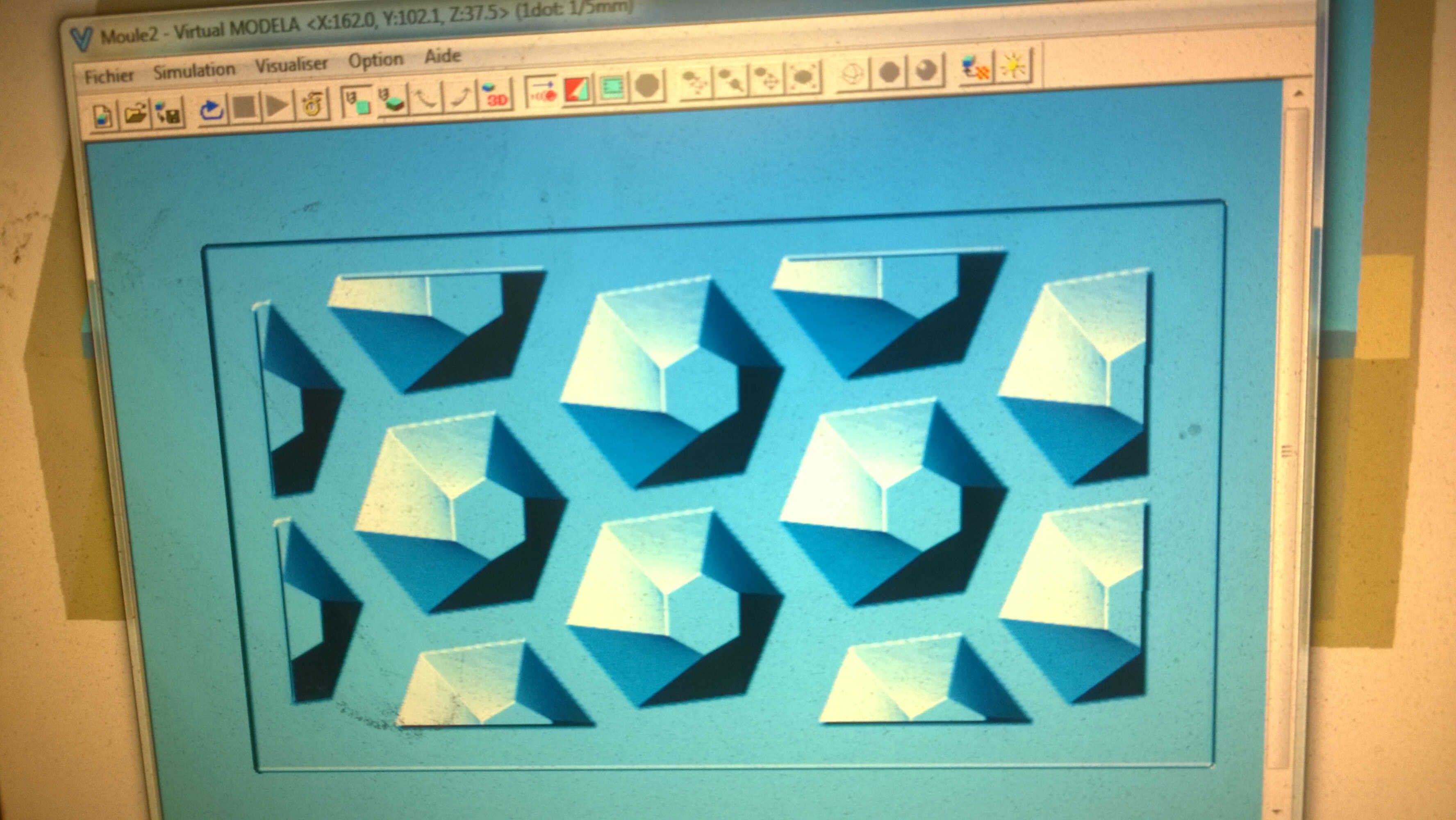
Milling
Time to mill. I did it the same way we did the test by:
- Drawing the center of the mold
- Fixing the mold to the bed with double-sided tape
tape fix
centred
- Importing the stl in Modela
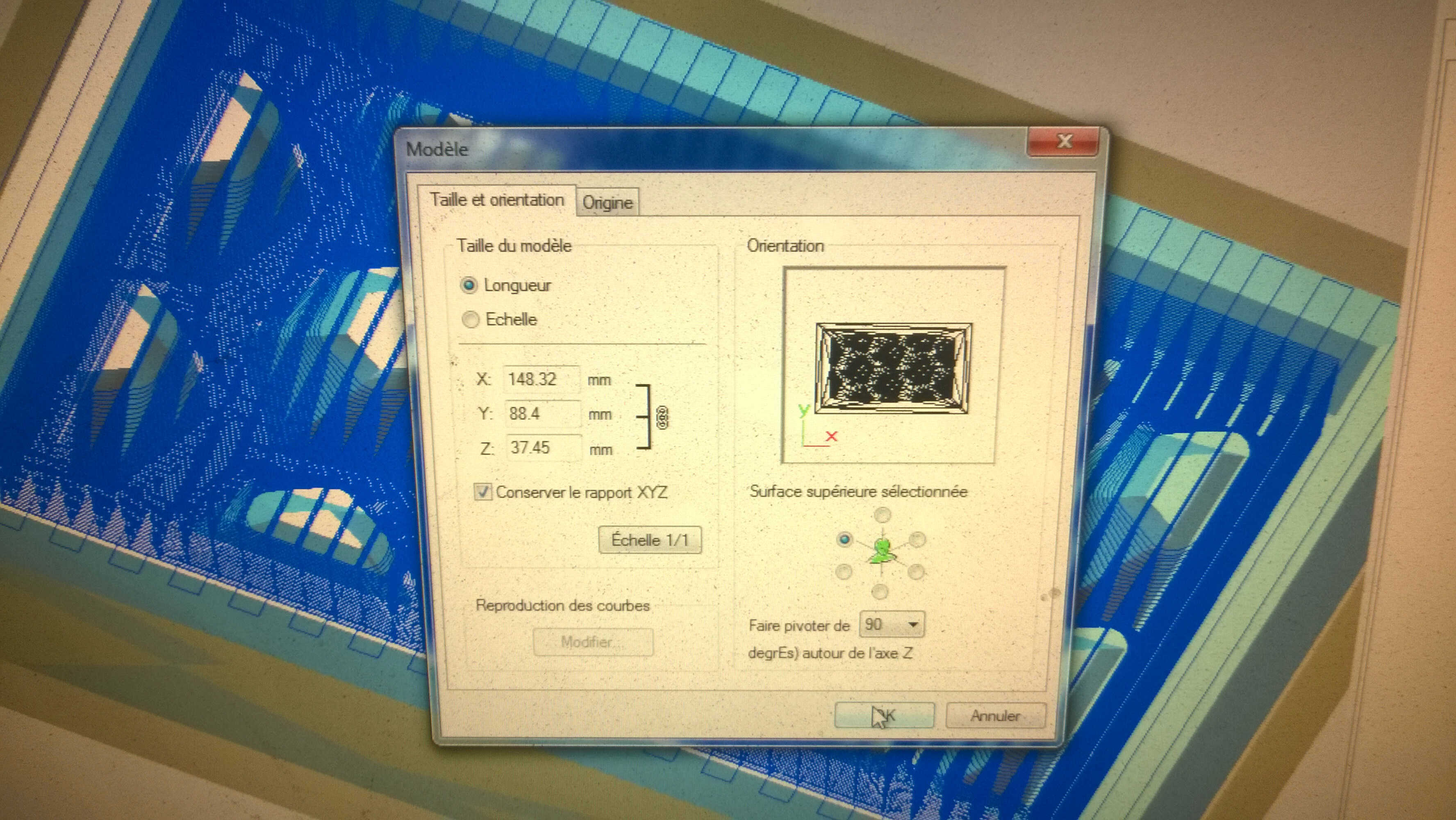
- Selecting rough cut
- Delimiting the area of milling (watch out about the piece orientation -compass icon in Modela)
- Using the predefined parameters for wax
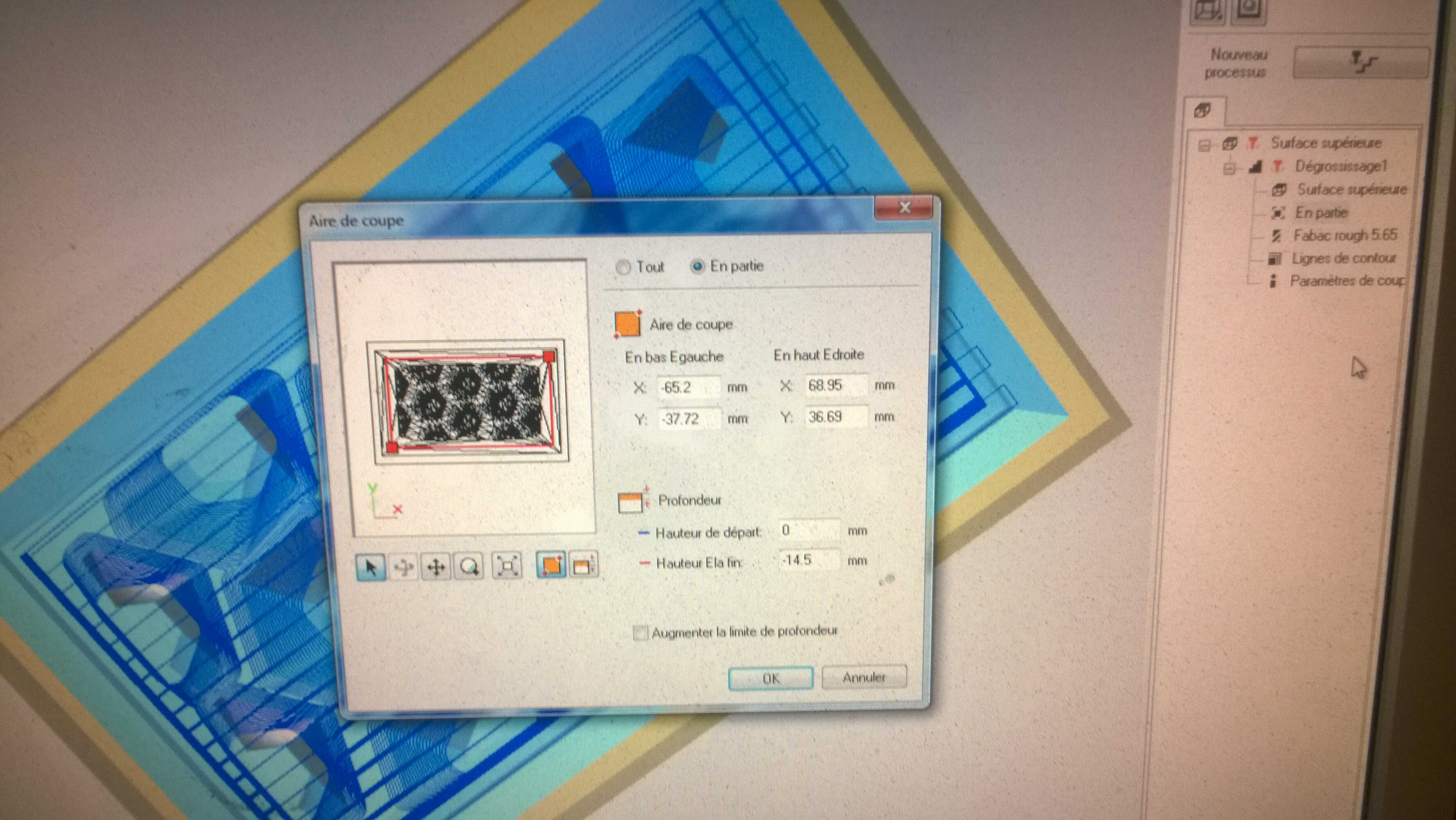
area delimitation
piece orientation
concentric lines
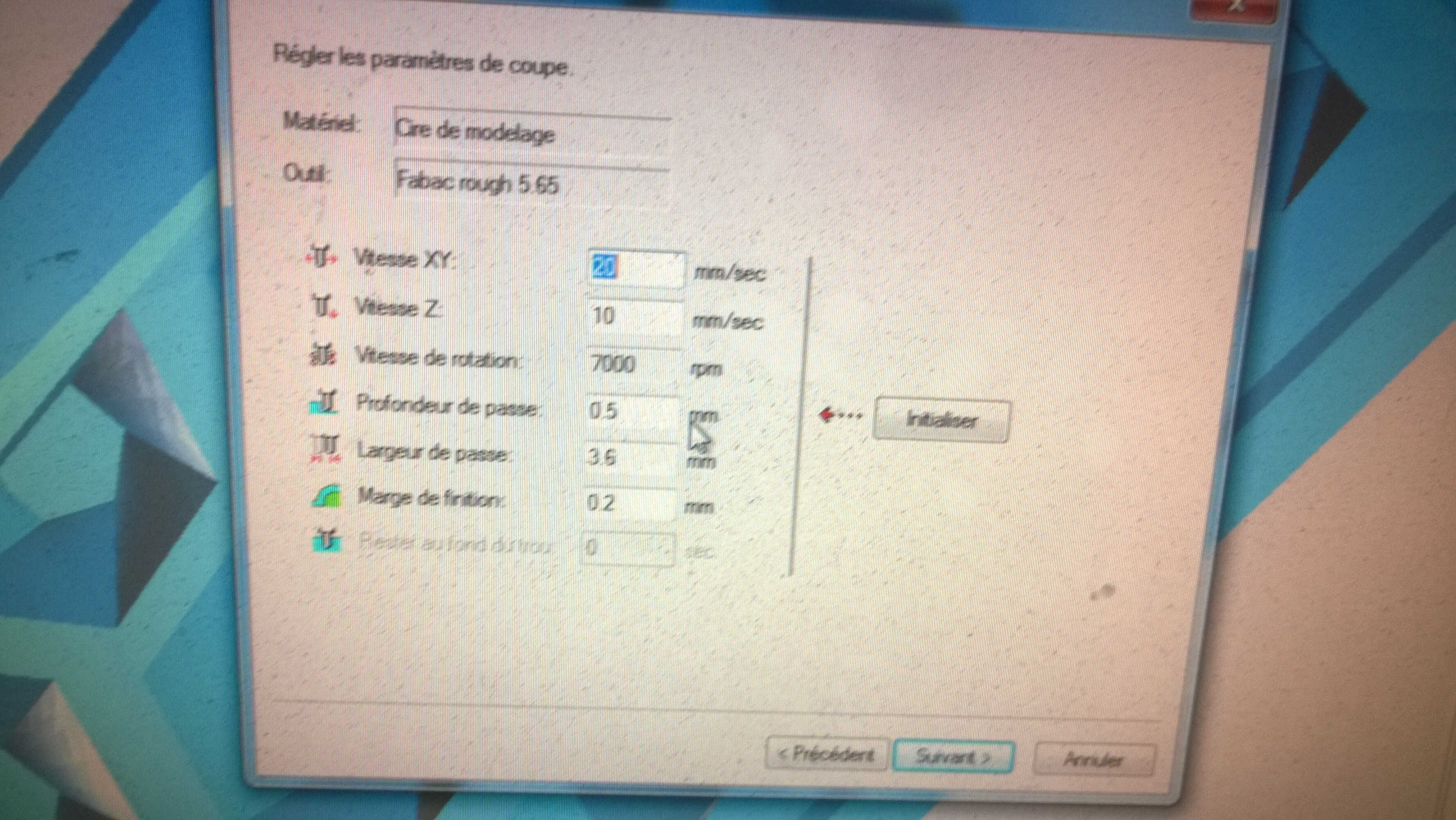
wax parameters
- Launching the preview in Modela (around 2 hours milling time forecast). Here a video from the preview computation:
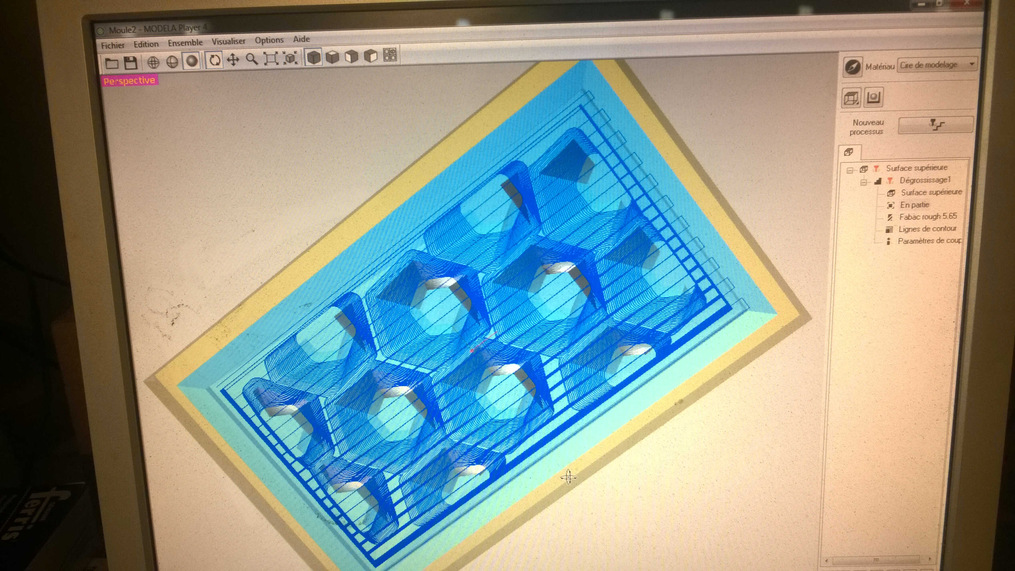
paths
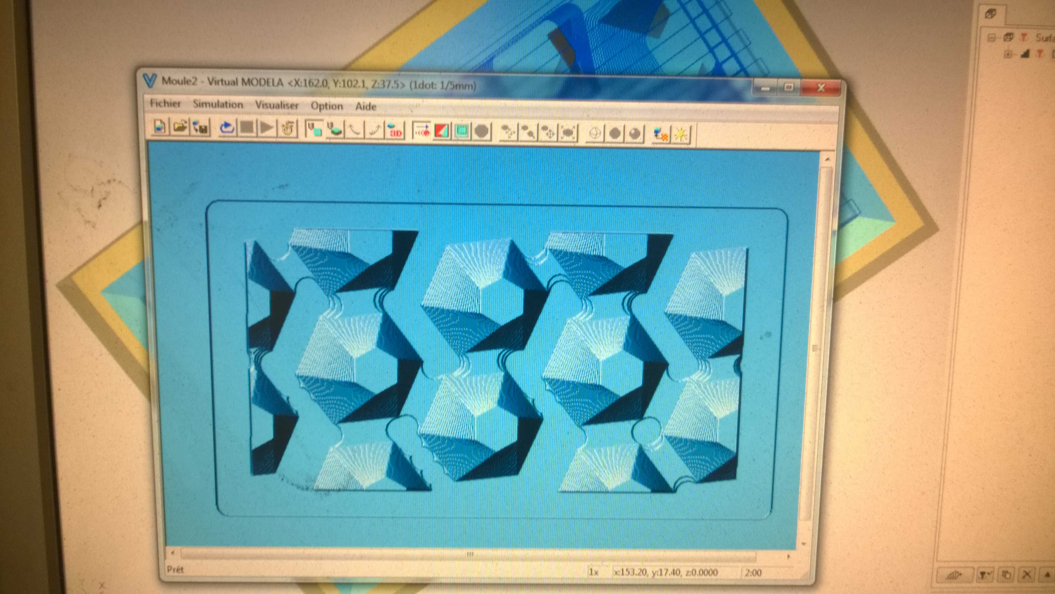
preview of the result
Here a video from the preview computation where you can see the end bit displacement:
- Defining the origin with the 5.65mm bit on
- Launching through Modela
- Putting the speed to 70% in Vpanel
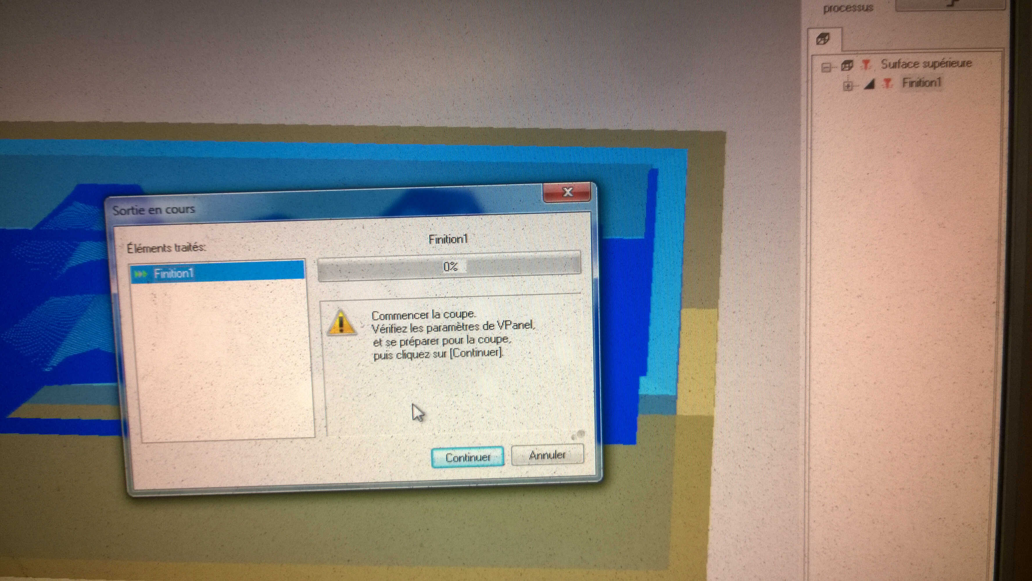
Modela to VPanel
chips
result of the rough path
Finish
I changed bits and relaunched a new process: Finish with paths along the X axis. For a smoother result I could have chosen X+Y. The finish took roughly an hour. Also I am unsure of how much the stepover was.
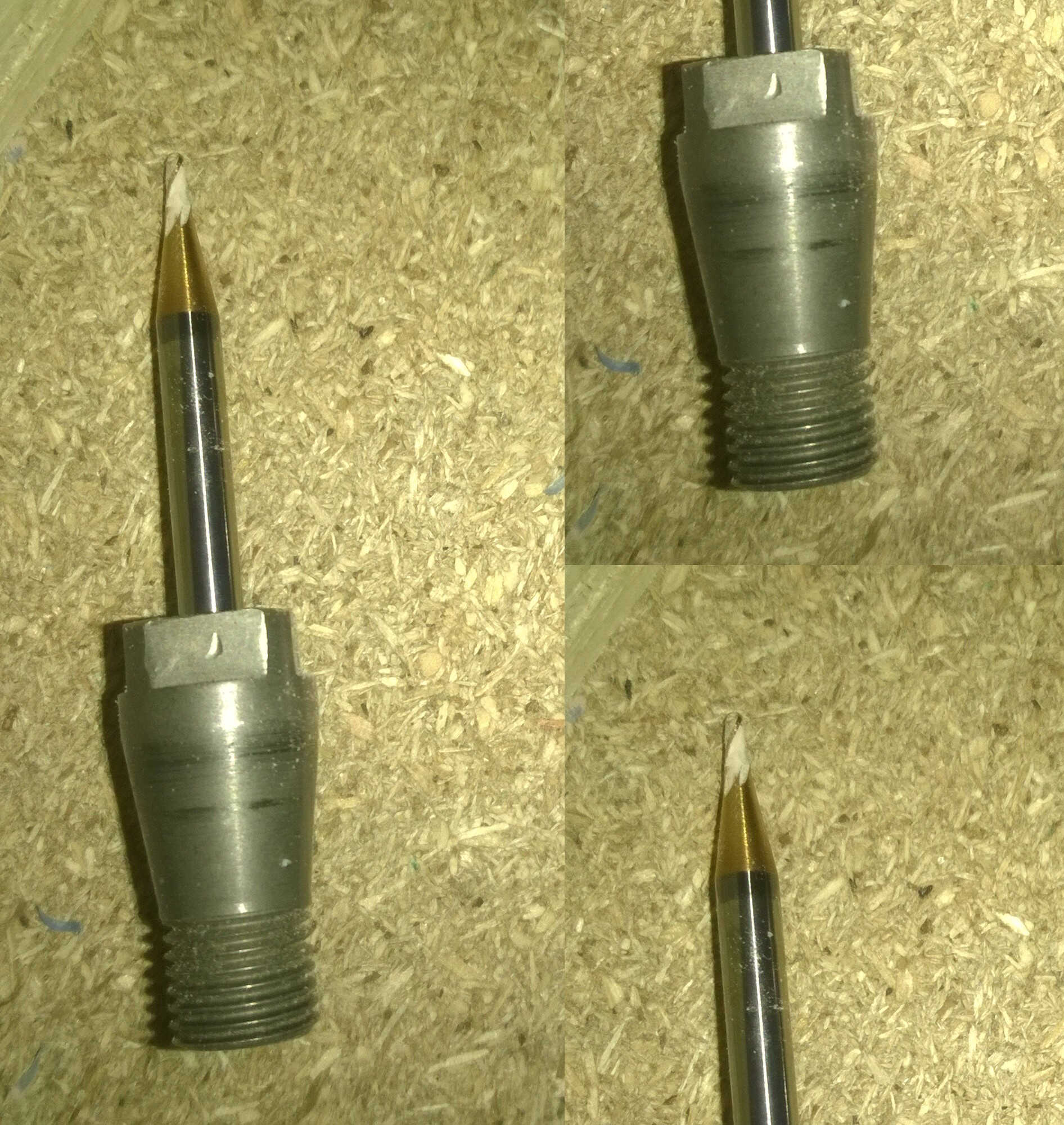
end bits
finish process
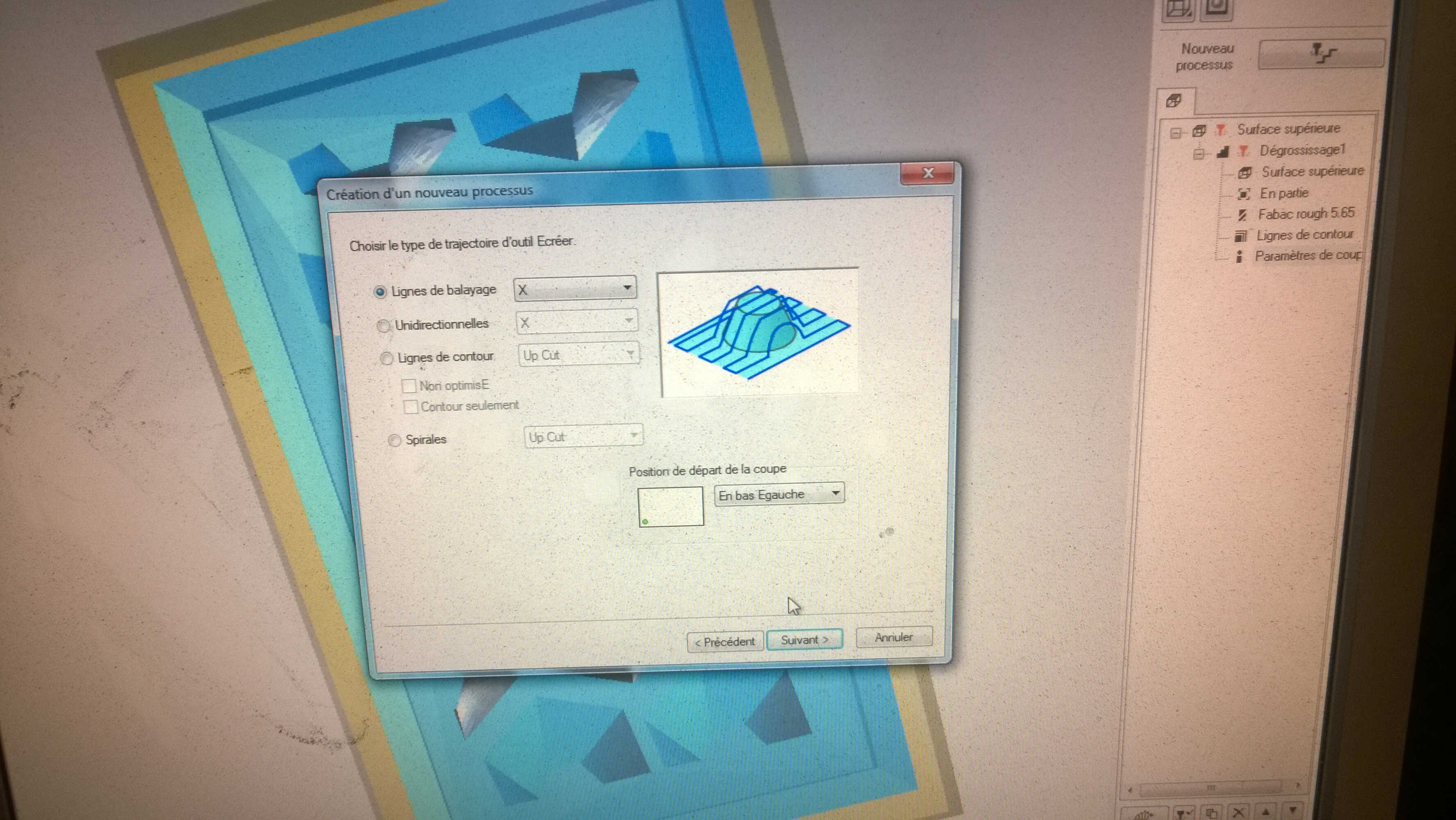
path lines along X
path visualization
finish preview
finish result
Here a video to aknowledge the speed of the process:
I regret wasting the chips, as I forgot they could be melt again.
regret
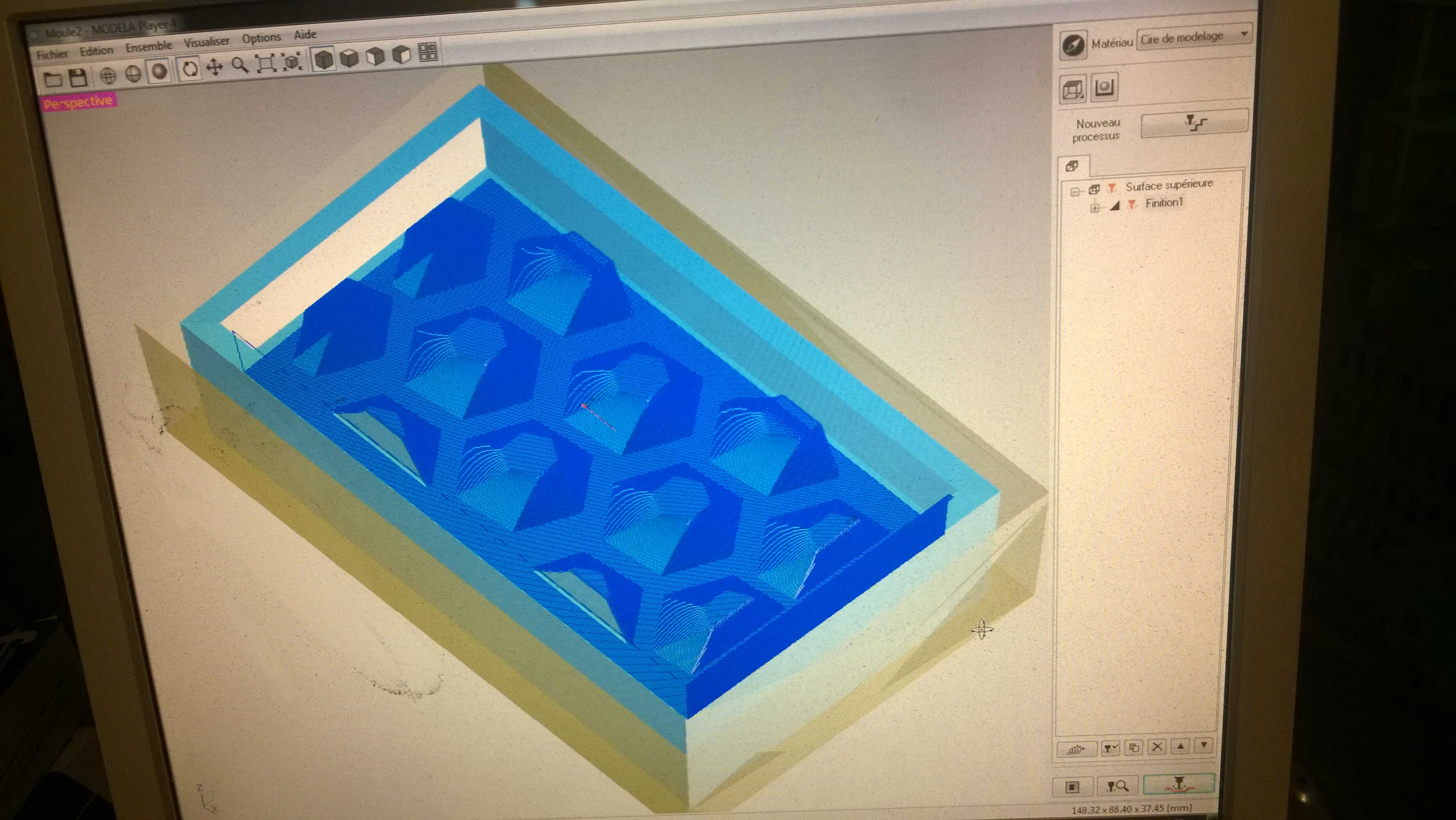
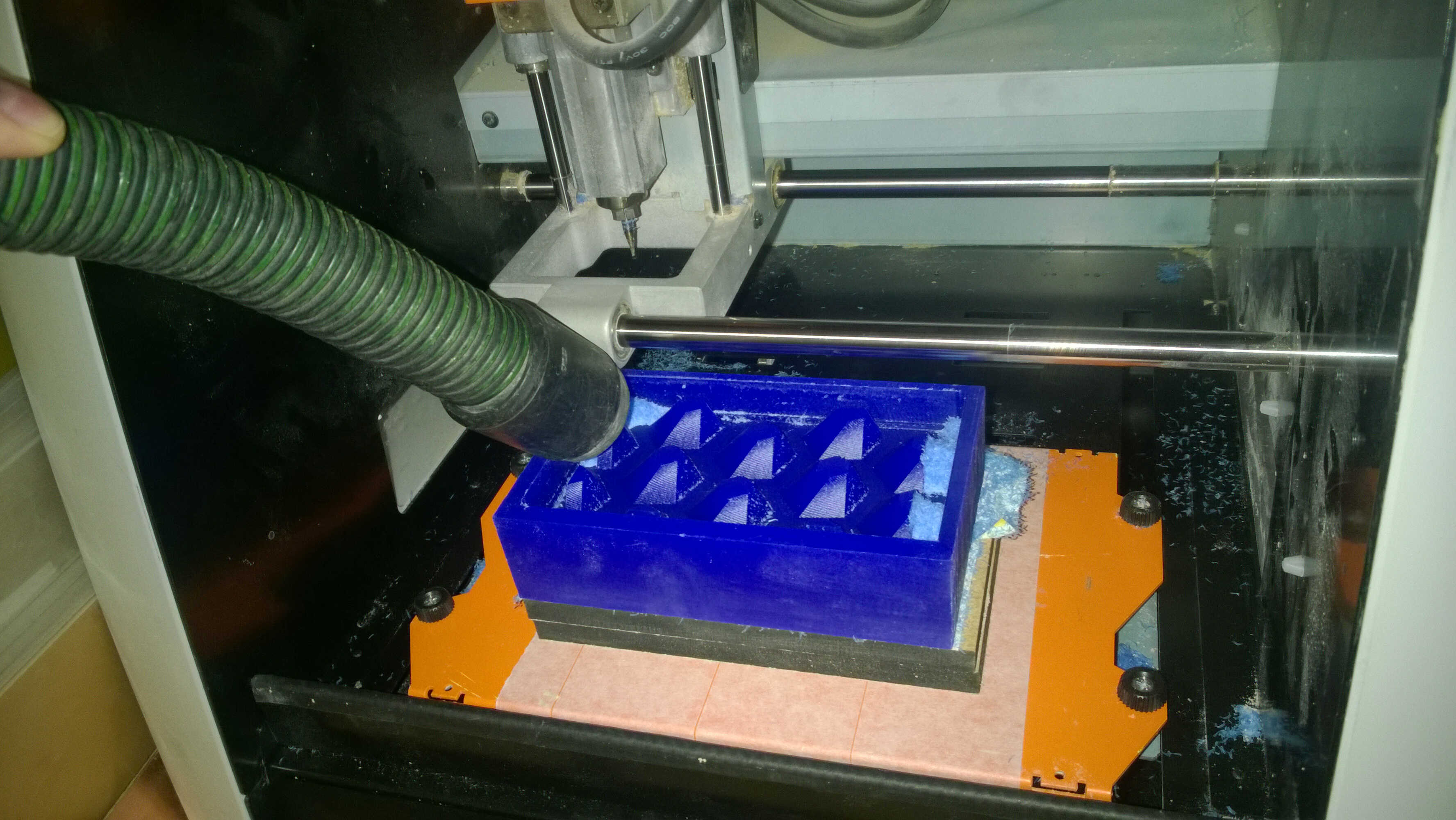
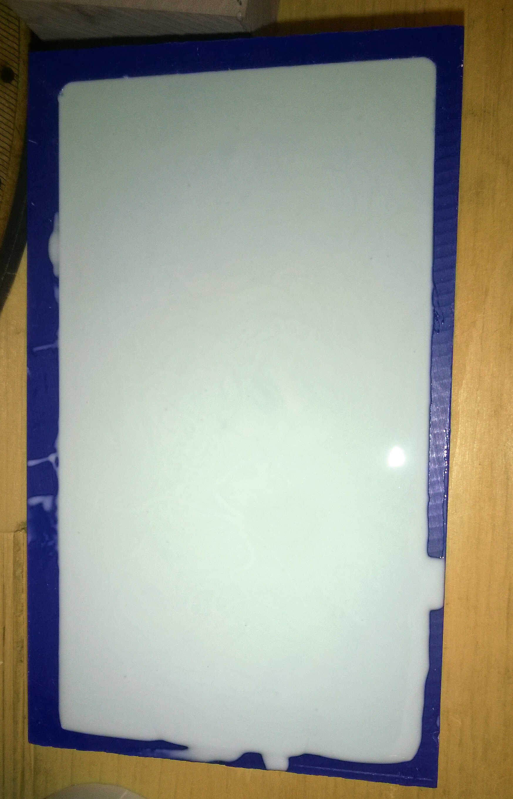
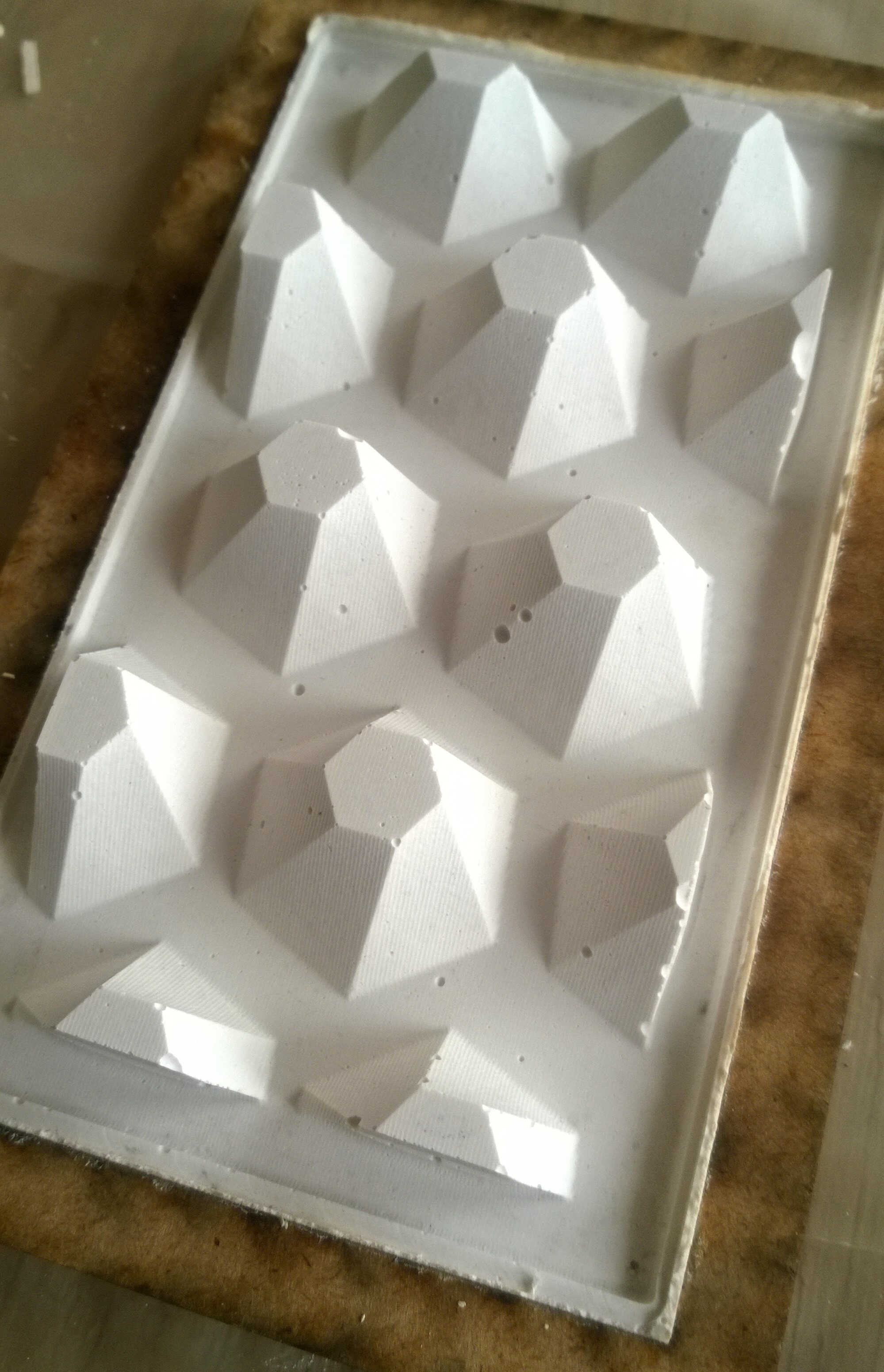
Silicon
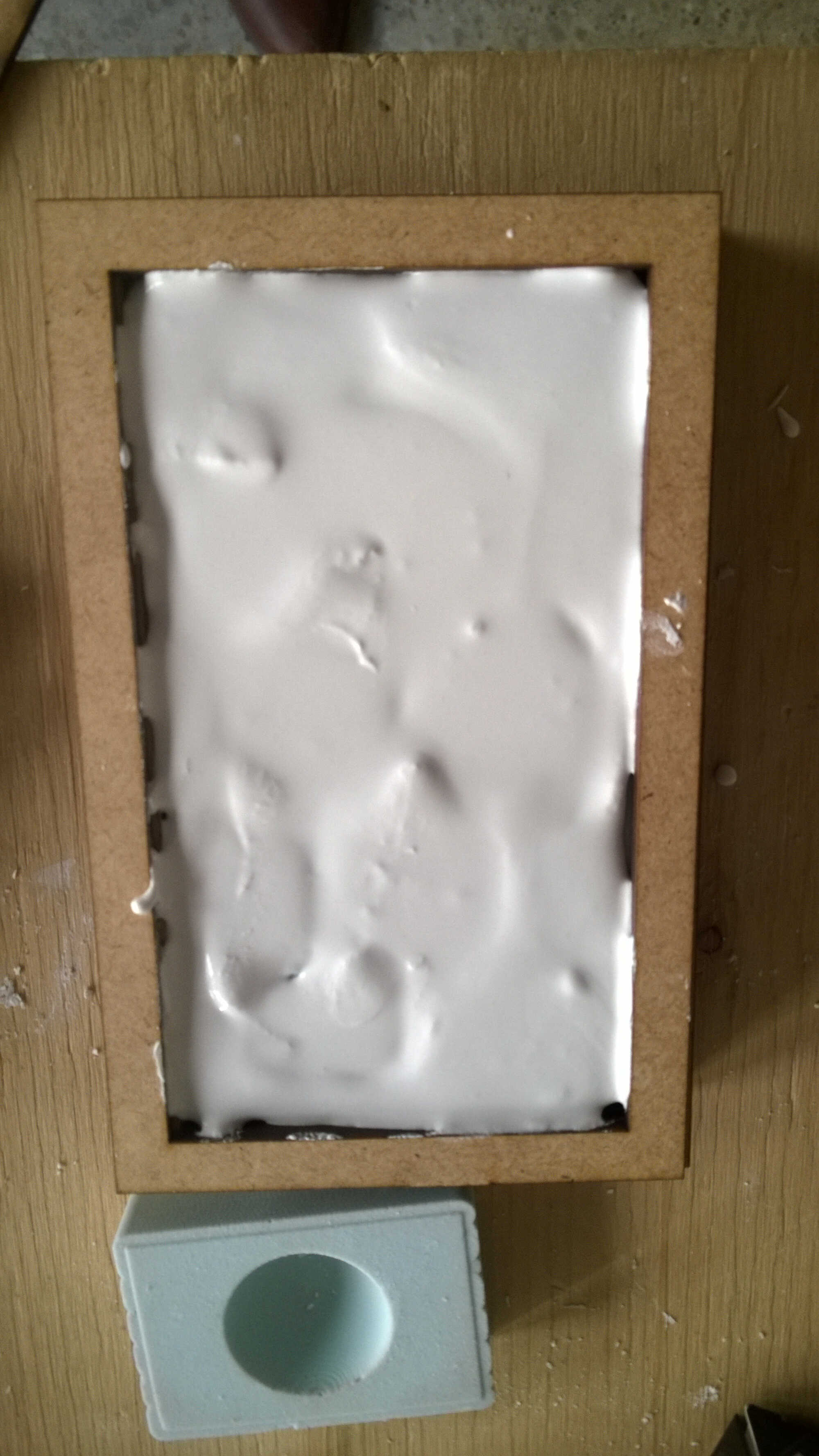
Now that the mold is ready, it is time to cast it. First with silicon with the same methodology as with the test.
the silicon
hardener added
homogeneous mix
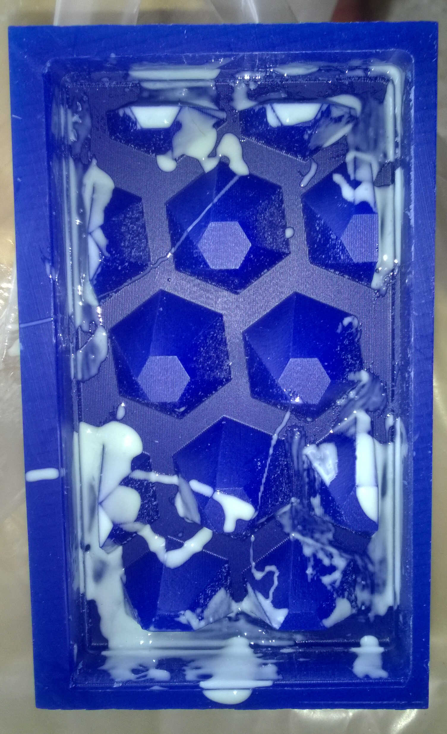
basting
pouring
setting
The silicon rested more than 24 hours. The demolding was a success. I was looking for a flexible piece but its thickness made it relatively stiff. The casting highlighted a defect I didn't see earlier: on the forms at the walls were "steps"". I don't know what made them appear.
mold out
thickeness
silicon steps
mold steps
Plaster
I picked plaster as the resin we have is quite irritant.
- Mixed 200g of plaster with 5cl of water
- Trying not to make bubbles
- Pouring from a height in the silicon
- Equalizing
- Setting 15mn
- Demolding
weighting the powder
slightly bubbly mix
first try with plaster
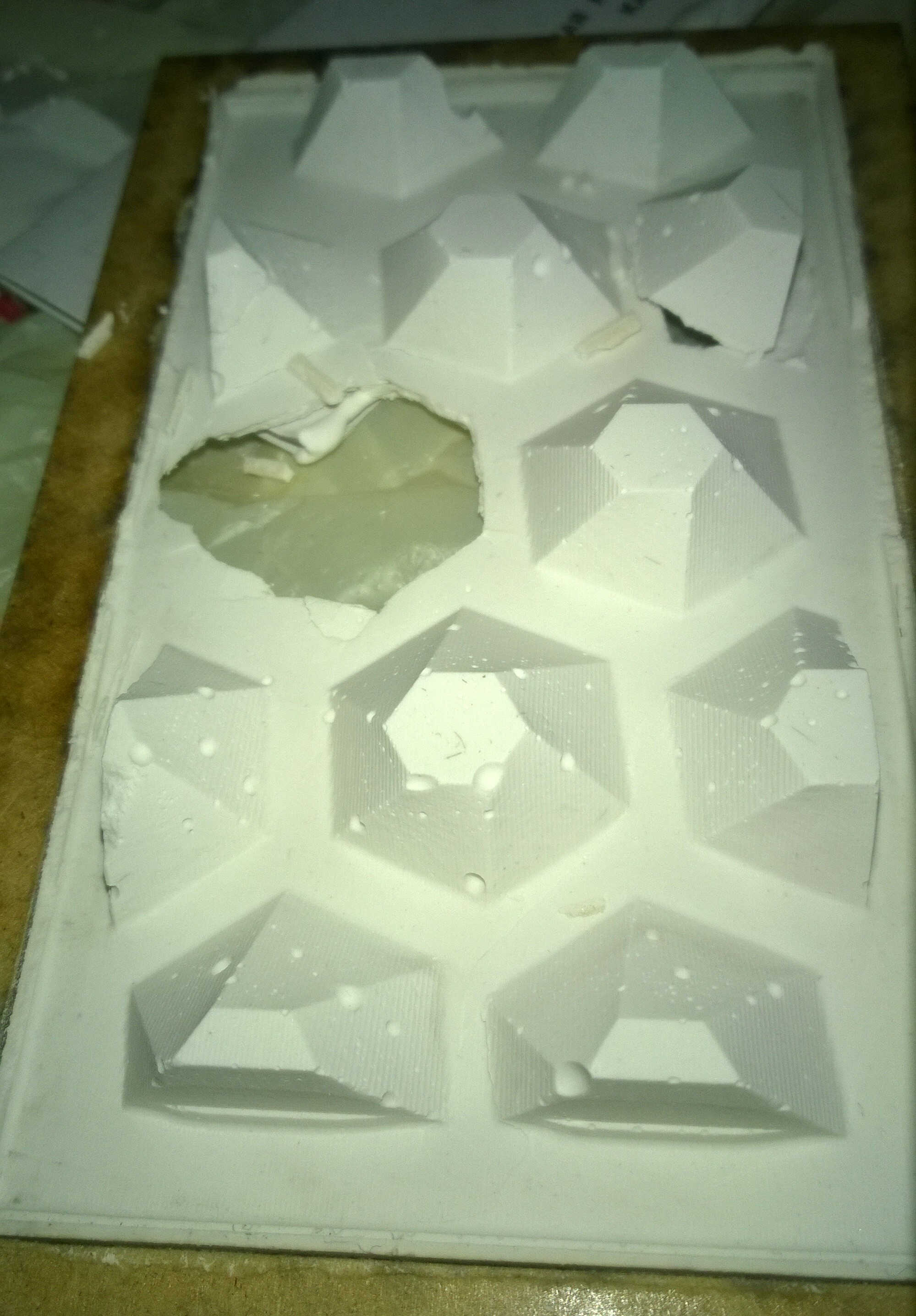
I thought the liquid would form a flat surface, I underestimated the wettability of the silicon. I tried to equalize with a cardboard used as squeegee. The resulting pieces were rounded. Also bubbles were visible and the edges quite delicate.
first batch
rounded piece
bubbles
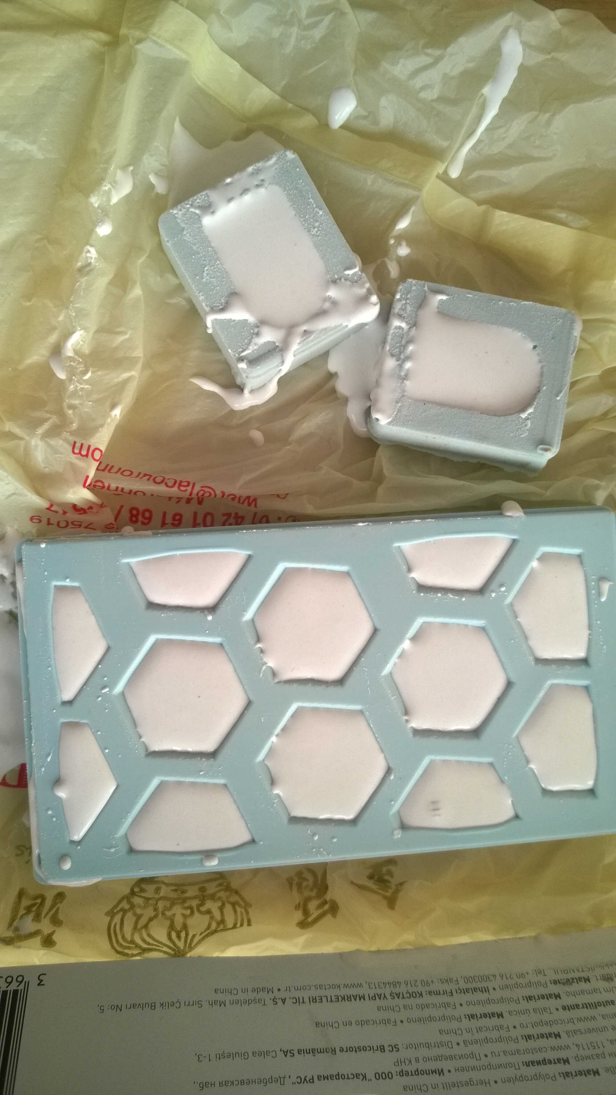
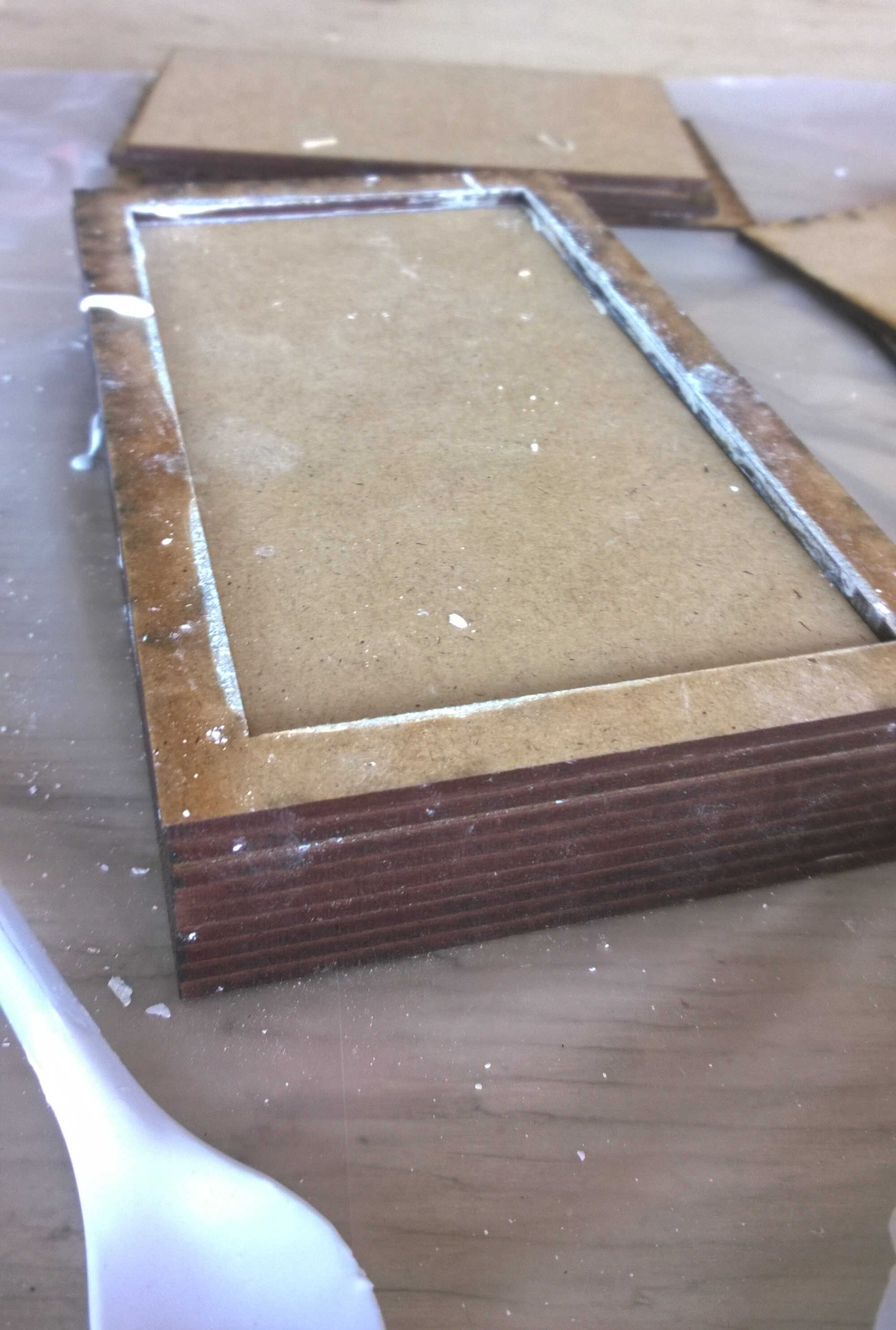
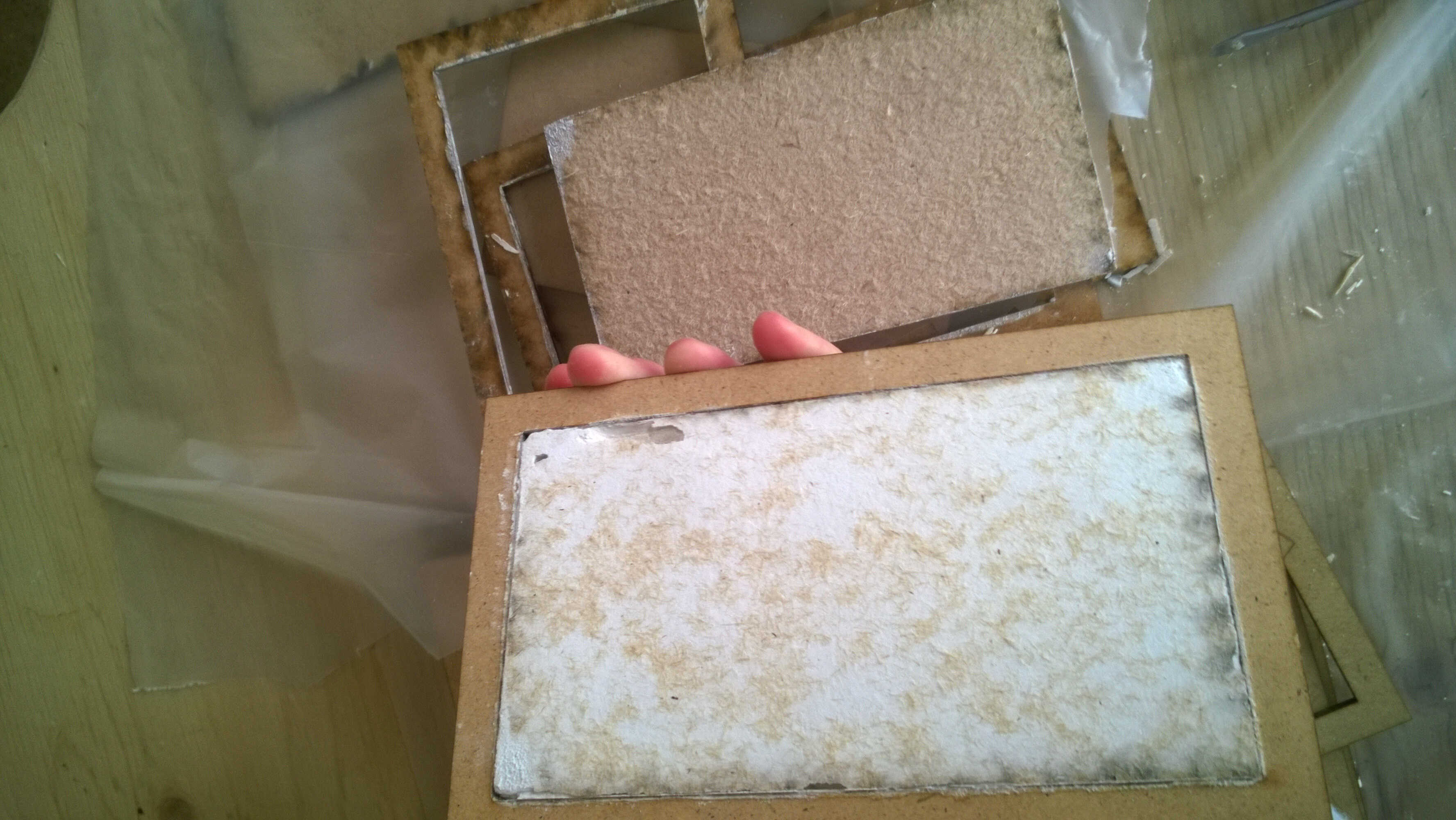
Frames
To have a flat base, I build a molding box with 3mm thick frames. For this I used my Fusion model from which I extracted the sketch of the edges of the depression. I then used the offset fonction and defined it to 10mm. I laser-cut 6 frames (6x3=18mm) plus one full. I superposed them around my mold, poured the plaster (100g-2.5cl water) then fit the inside in the upper frame. I pressed it and waited half an hour for it to set.
superposing
spreading with a spoon
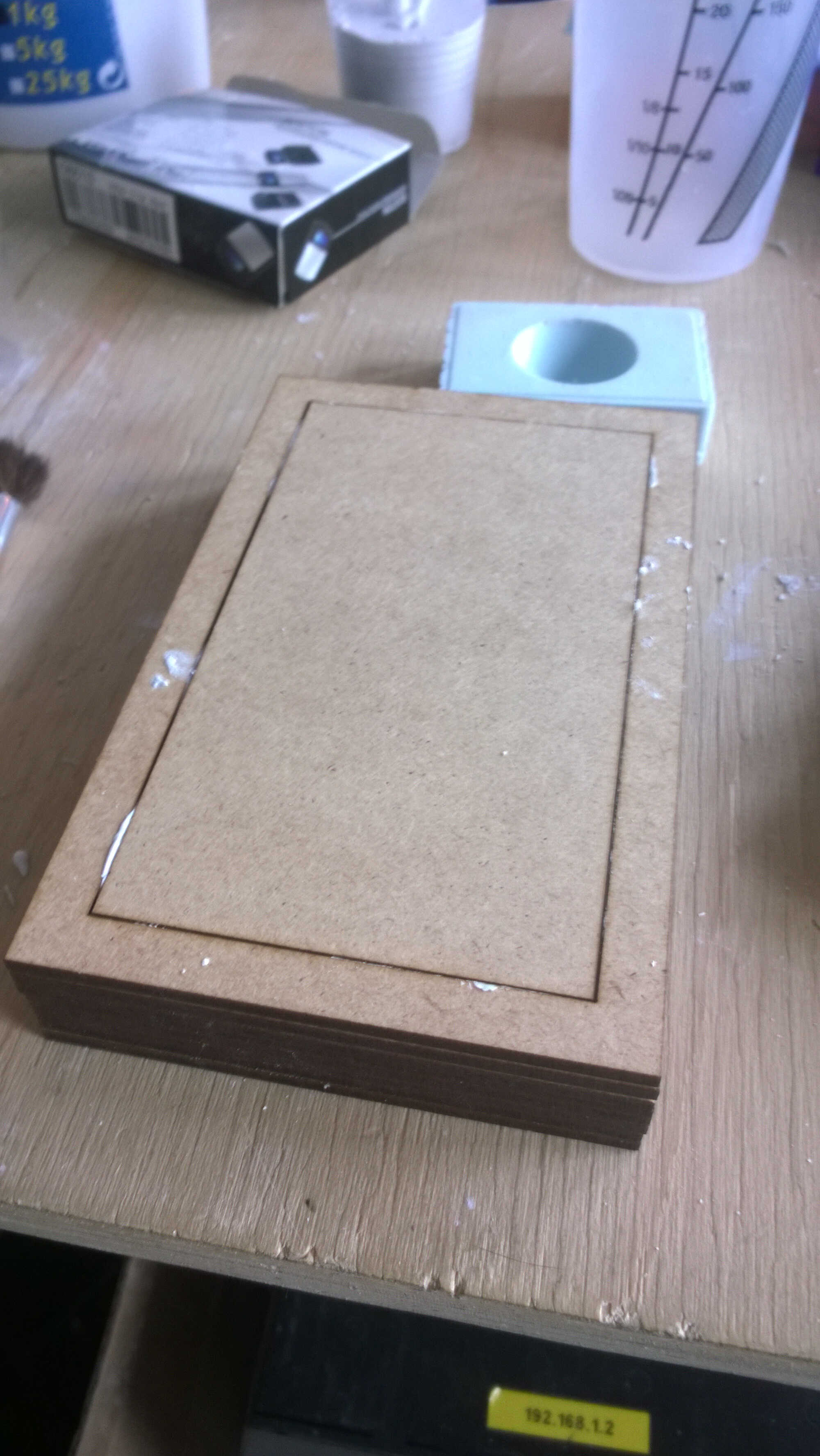
upper flatening
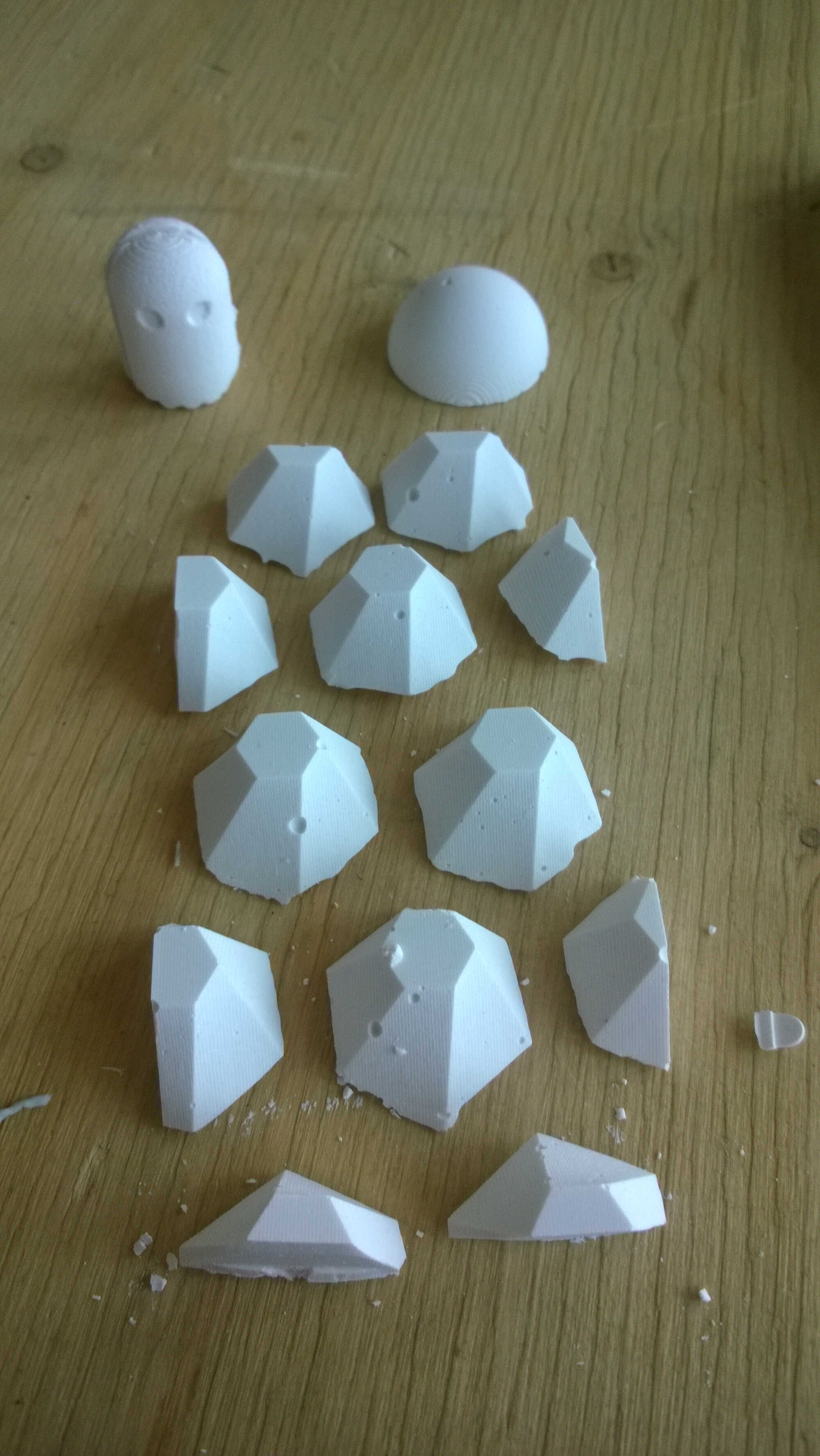
The plaster felt a bit wet when I removed the frame probably due to the little contact with air. A crack formed.
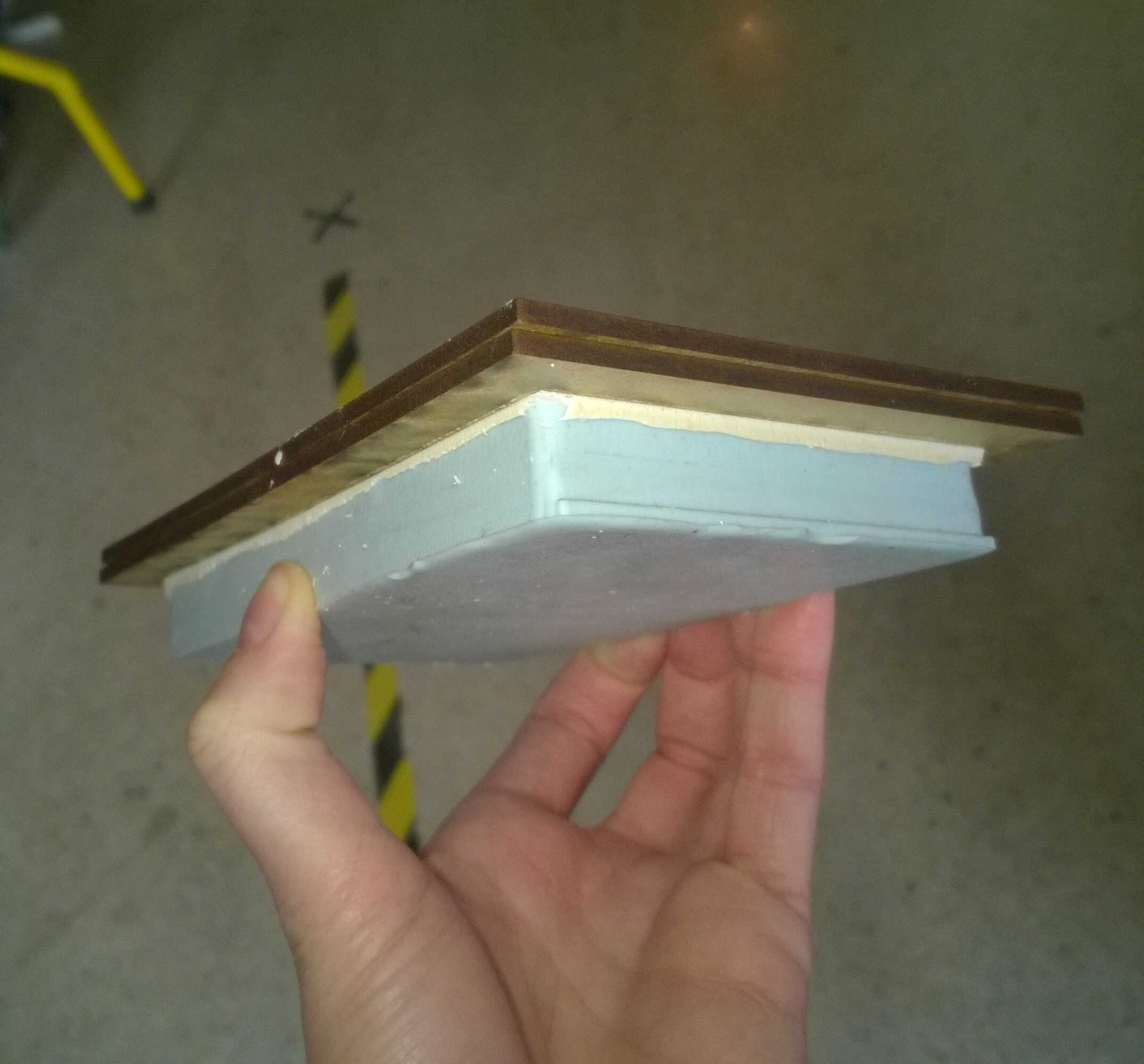
removing frames
removing frames
face up
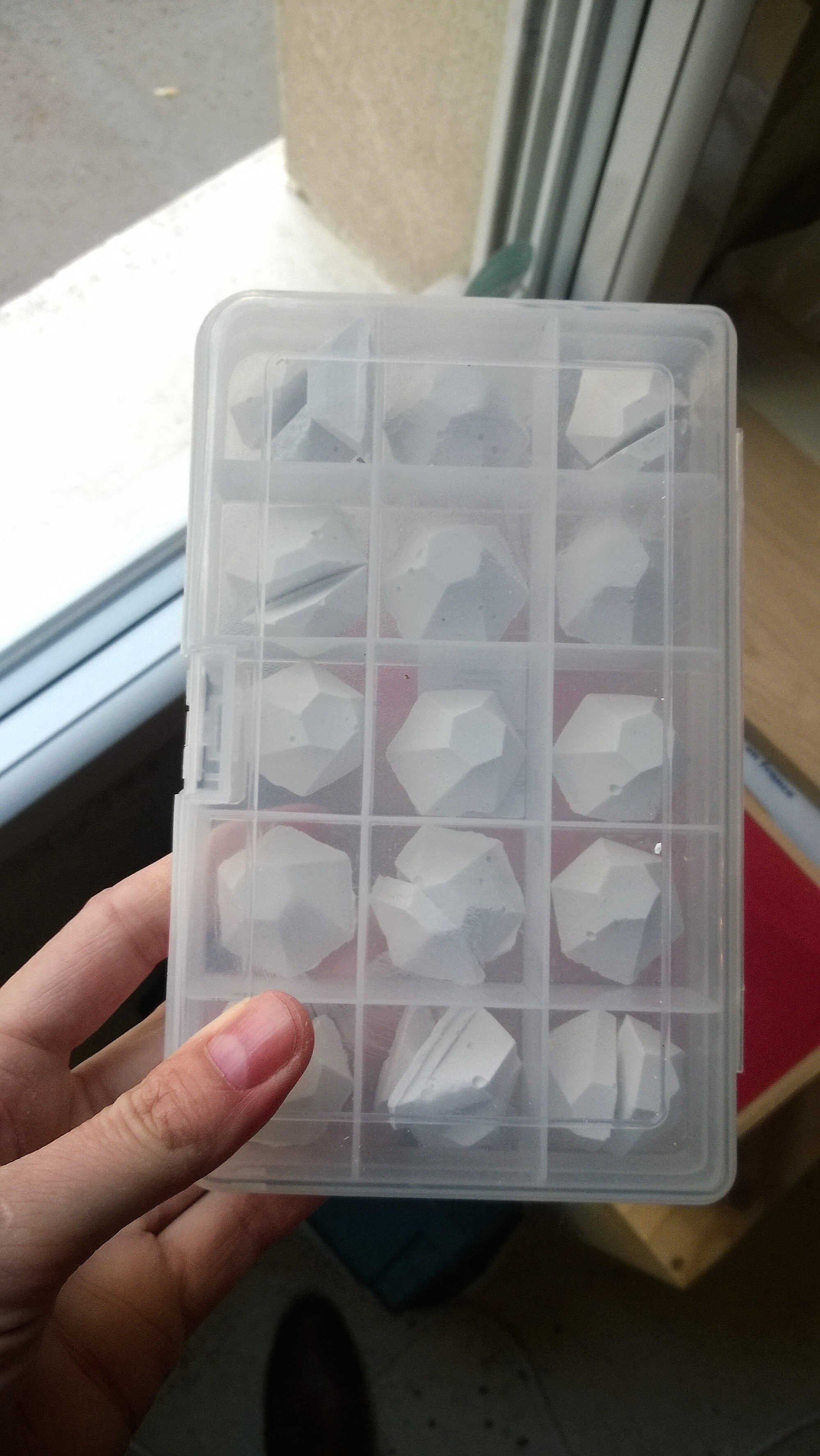
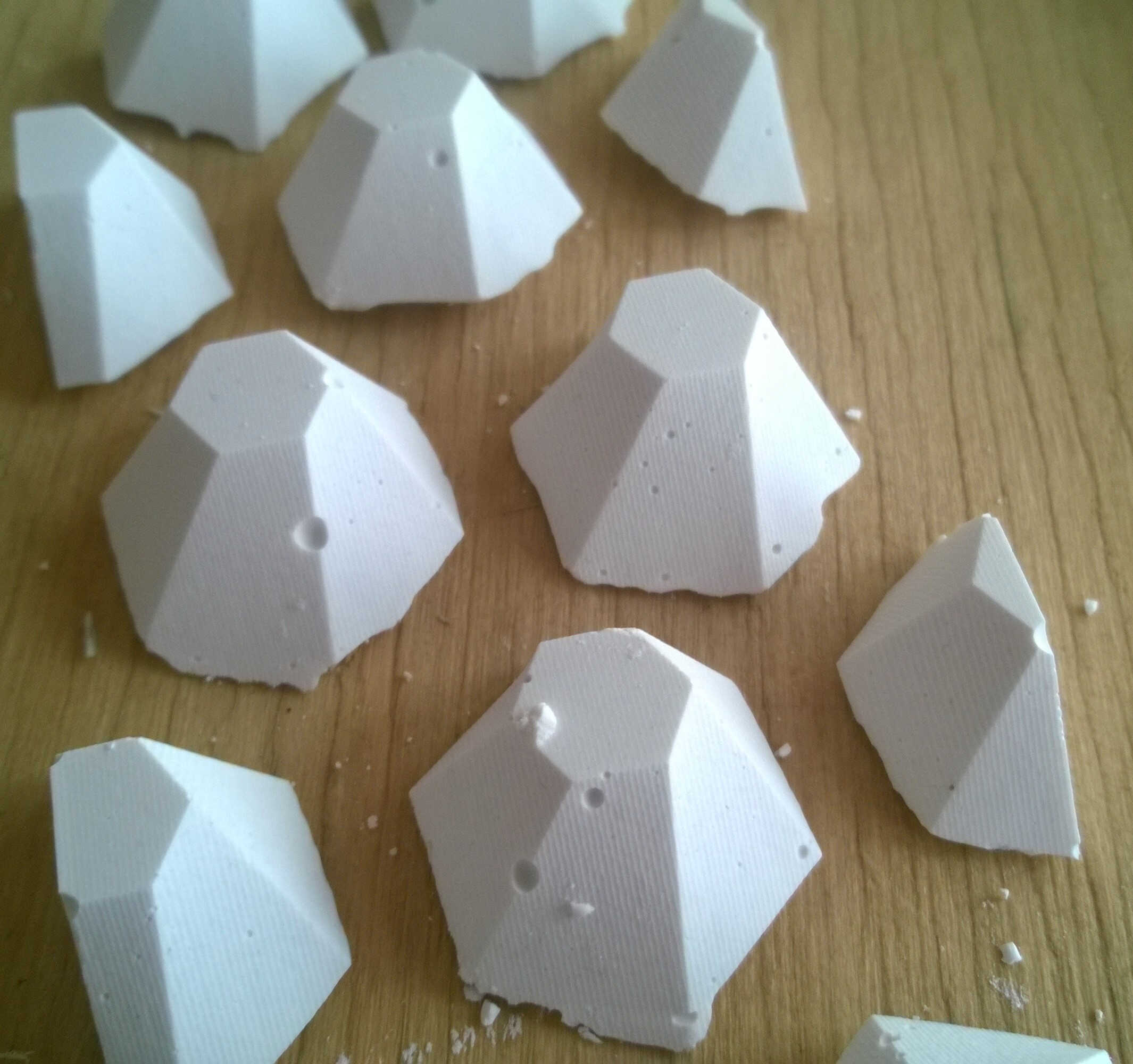
pieces collection
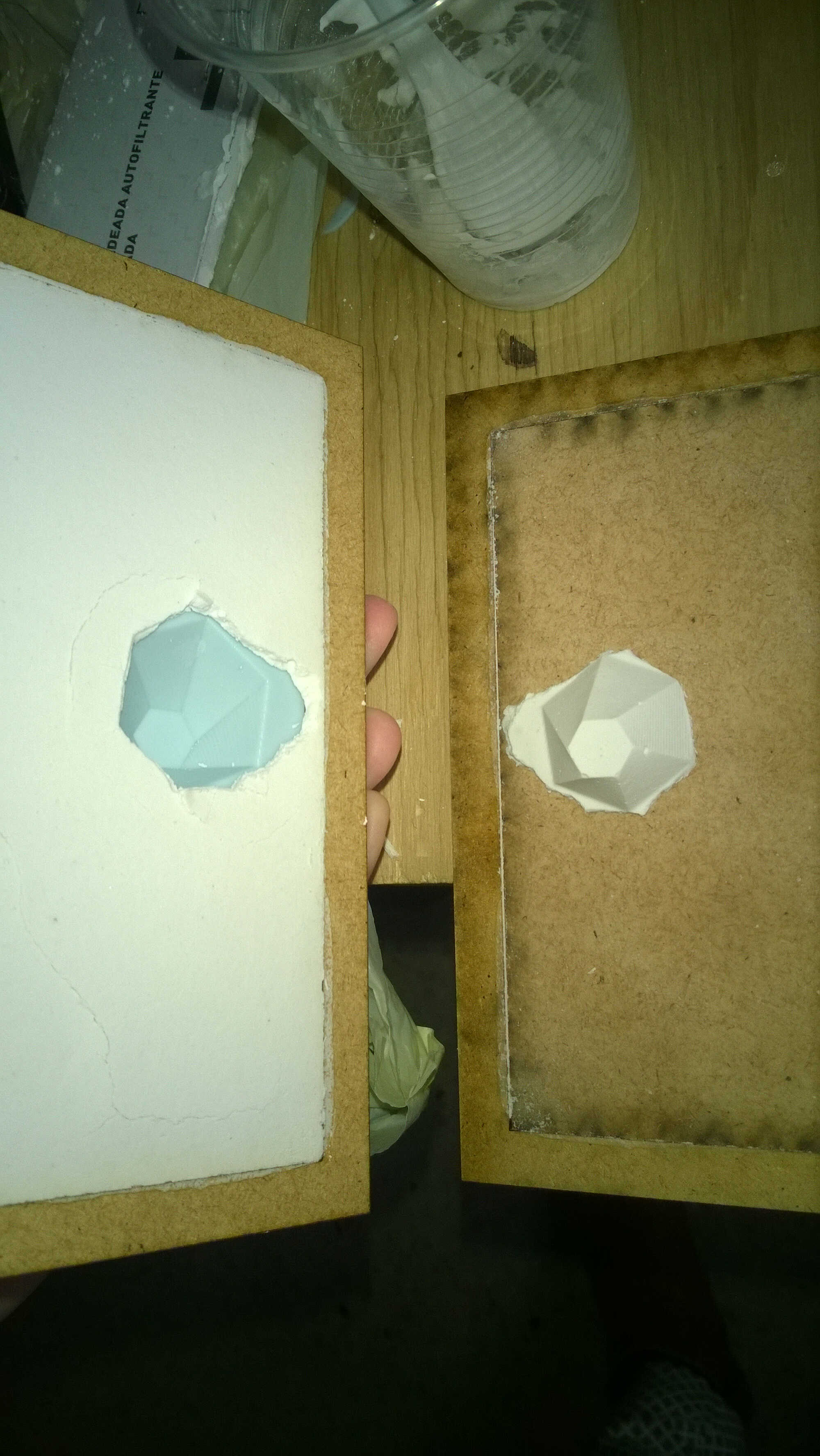
I concluded that the upper thickness was to thin, so I cut 2 frames more with the laser. I also decided to increased the length of curing to an hour.
more frames
whole tile
medium dissolved
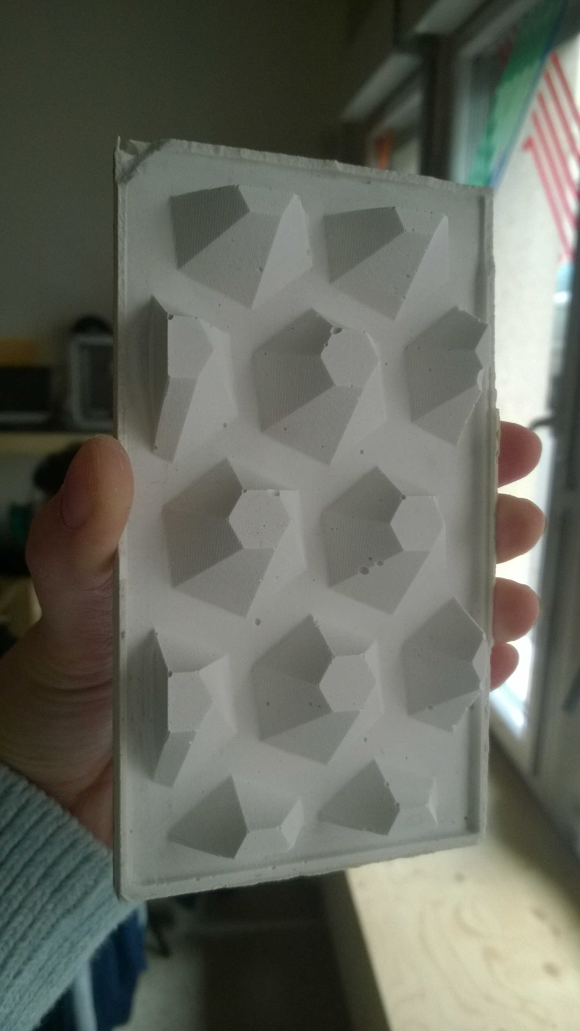
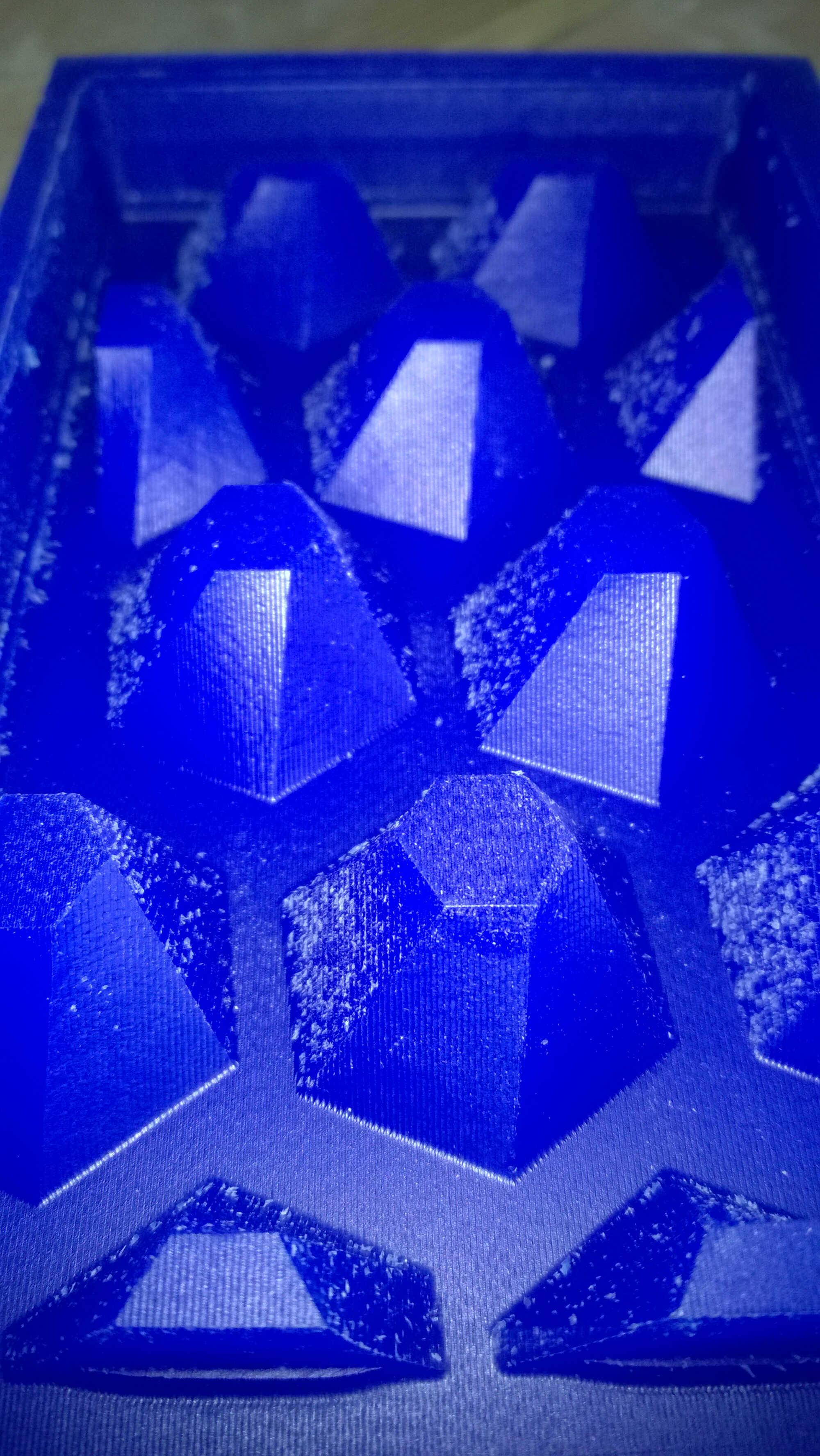
light catching
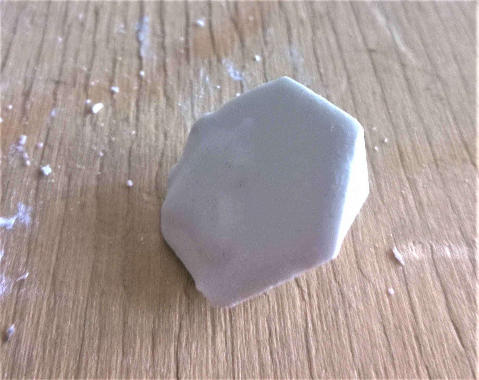
The demolding was more of a sucess, the plaster was still slightly wet and warm though. Bubbles were still visible but the tile came off 95 intact%. The long curing resulted in a dissolved medium. I probably should have used plain wood, the resin probably reacted with the curing plaster. This is encouraging, the relief nicely catches the light.
Future work ideas
- Maybe in altering my design it could be used as a sundial.
- The bubbles are seen as defect, it would be nice to have a design they enrich and trying to increase this effet with a syringe.
- My design is not symetrical, this made me think of a 3D design which will change signification depending of the level of casting fluid and of the mold inclinaison.
Brainstorming
Thomas showed us that one student last year used this week to design tires for its robot. I thought it was a good idea to design a final object flexible as I enjoy the touch of silicon.
I drew a parallel with my project. Soles can be flexible, why not my floor tiles?
Also, as I was looking for a parallel with nature design, I though of composite.
Why not a flexible tiles with ponctual hard parts?
Those hard parts were first given a resonance function, they would amplify the sound/vibration issued from the steps. As I wanted to use plaster this didn't make sense as plaster is used as isolant -to fire, to sound... I may use plaster for separation between tiles. I considered designing those hard part as massage balls, for barfoot usage and as simple ornaments.
Finally I decided those hard parts could be used as interruptors once flexible copper circuit will be added to them. They will be able to provide precise information on the displacement.
Outcome
The silicon part was stiffer than I imagined and I couldn't obtain a flat base without adding a base. Next time I should try with a silicon mold thinner than a centimeter.
Regional
Good review, back to normal after the shameful group project.
Thomas suggested I could use cling film between plaster and medium to prevent its dissolution. I appreciated learning through Miguele's -furnace-, Denis's-biomimicry superhydrophobicity- and Bianca's achievement-oil spill reuse-. This will push me to be more creative.
I learned:
- that I could compute the volumes of liquid needed in my mold with Fusion.
- about dental polymers
- that Epoxy is used in microfluidic
- about Tippe Top