Week 4 - Electronics Production
Assignment
- make an in-circuit programmer by milling the PCB
Making a circuit by milling the PCB, soldering the components and then programming the microcontroller involves a lot of steps, usually not interchangeable. Hence, I have decided to put all these step in a ordered list for future reference (and I plan to improve this list week after week).
Milling a PCB - Step by step guide
UPDATE - refer to week 10 for a full and updated lists of the Roland milling parameters!- Design the PCB or download an existing layout - at Opendot we have a bunch of AVR ATtiny44 in the small outline package (SOIC), hence the FabISP hello-ISP-44 board based on the ceramic resonator is perfect. In the next weeks I will have more time - I hope - and I will be able to mill and solder also the version with the crystal and try other circuit-printing processes. So, I downloaded the high-resolution version of the PCB design from the Fab Academy Electronics Production page (both the trace and the interior images).
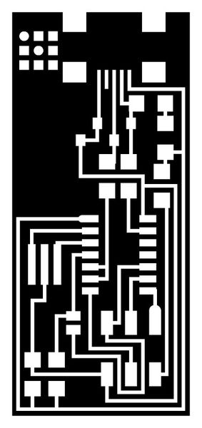
- Open fabmodules, import the PNG trace, choose the Roland .rml output (we have this kind of machine at Opendot) and the PCB trace 1/64 (which equals to 0.015" - 0.40mm).
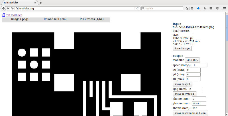
- At this point, select the right the machine (at Opendot we have an MDX-40): fabmodules auto-completes the settings, but the default values are not always the best choice!. Specifically, I changed:
- zhome = 10 to move away the tool at the end of the process;
- x0,y0,z0 all to 0, so that the zero of the image is the homing point of the machine;
- 2 mm/s as machine speed (Enrico advised us that this could help fragile path to last);
- cut depth to ~0.08 to reduce the wear of the tool;
- the diameter of the tool used for milling path is 0.4 WARNING - this end mill is very expensive and should be handled with care!
- and finally, I set the number of offsets to 2, but next time I will try -1 to remove all unused copper.
- With this new setup, click on "Calculate the path" and save to outcome (an .rml file) on the USB key.
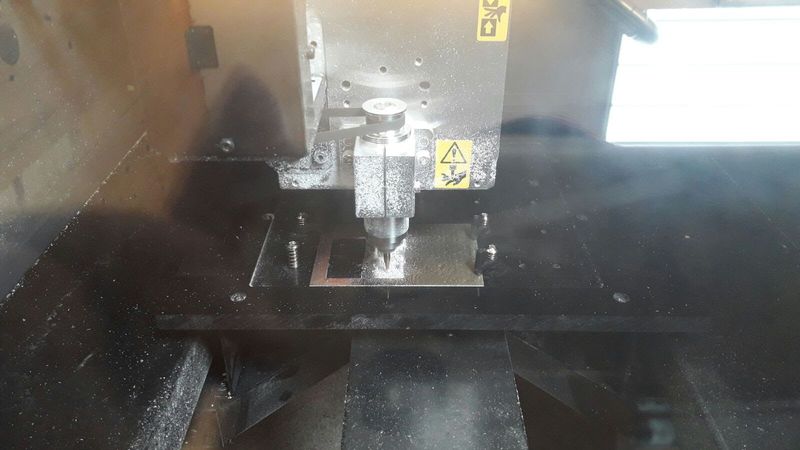
- Move to the milling machine, turn on the computer and the machine itself.
- Clean carefully the surface of the table from dust or glue (remained from a previous cut)
- Fix the copper plate using double-sided tape
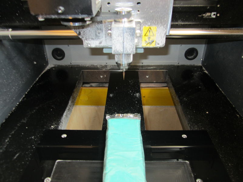
- Mount the 0.4 end mill WARNING - always put a piece of modeling clay under the spindle to save the end mill in case it plunge).
- At this point, open the vPanel software to set the XYZ origins as follows.
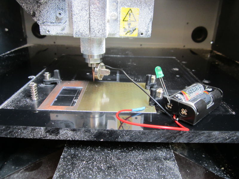
- First, set the zero of the Z axis moving it really, really carefully! During this phase the end mill should descend with small steps and be stopped when it brush against the copper layer. Use a piece of paper or the smart circuit available at Opendot: when the tool touches the copper, the circuit closes and the LED lights on. The LED flickers when the Z is perfect.
- Then, move the Z axis about 20 mm up to not scratch the board.
- Now move the heading to the XY origin and set these coordinates as the new XY zero.
- Set the current Z (-20) as the new home
- Click on "Cut"
- Load the rml file from the USB key
- Click on cut - it should start moving in the space without cutting the plate. Check that the XY origin are correct and the end mill moves as expected
- Spread a bit of oil on the board to make the end mill move smoothly and to reduce the dust WARNING - the oil must not go underneath or the tape will stop to glue
- Move down by 20 mm the end mill so it is at the correct Z origin (the surface of the plate)
- Set current Z as the new Z zero
- Set the spindle speed to 15000 rpm
- Launch the cut.
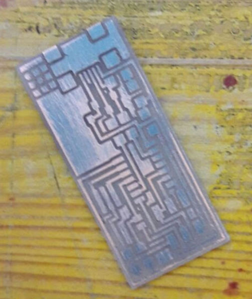
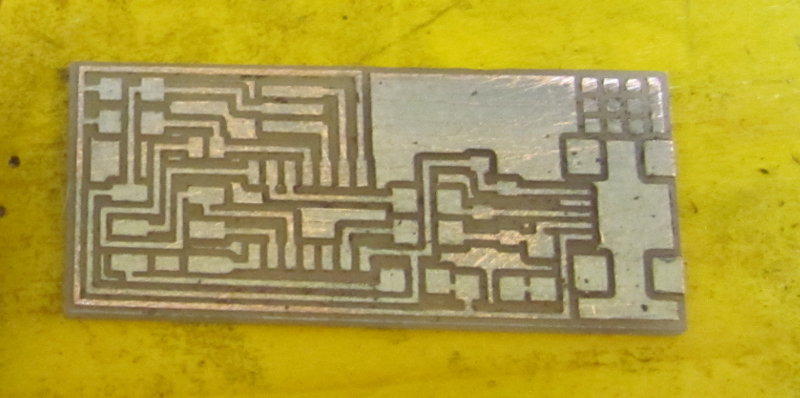
- If the milling process went fine, you can move to the cutout image
- Open fabmodules again, import the PNG trace, choose the Roland .rml output, choose Outline cut (1/32), set the MDX-40 machine and change the following default values:
- x0,y0,z0 all to 0
- Cut depth to 0.75 mm
- Stock thickness to 1.5 mm
- Tool diameter to 1.5 mm
- Offset to 1
- With this new setup, click on "Calculate the path" and save this new .rml file
- Swap the end mill with the 1.5 mm one (WARNING - remember the modeling clay under the end mill
- Set the new zero of the Z axis. WARNING - leave the XY zeros untouched, but set the Z zero again when you change the end mill. Otherwise, the tip will either cut the air or it will break down piercing the table!!!
- Load the .rml file
- Launch the cut
- If the outcome is fine, you can turn off the machine
- Remove carefully the plate from the table and clean it, removing tape and dust
- Cleaned the PCB using a small cutter blade and, then, with a cloth plus alcohol or a toothbrush to remove the copper particles left on the board. WARNING - clean carefully, because this small pieces of copper "dust" are really dangerous: they could go between two traces and generate a short circuit (and fry your IC, your USB port, your PC and... who knows :-)
- Now you are ready to solder components and program the microcontroller!
Bill of Materials (BOM)
A list of all the components needed to completed the circuit follows:
- ATTiny44 (x1)
- 20MHz Resonator (x1)
- micro USB connector (x1)
- 100Ω Resistor (x2)
- 100kΩ Resistor (x2)
- kΩ Resistor (x1)
- 499Ω Resistor (x1)
- Jumper - 0Ω Resistor (x2)
- 1uF Capacitor - (x1)
- Zener Diode (x2)
- Pin headers (x6)
Soldering
So the board is now ready to host components...
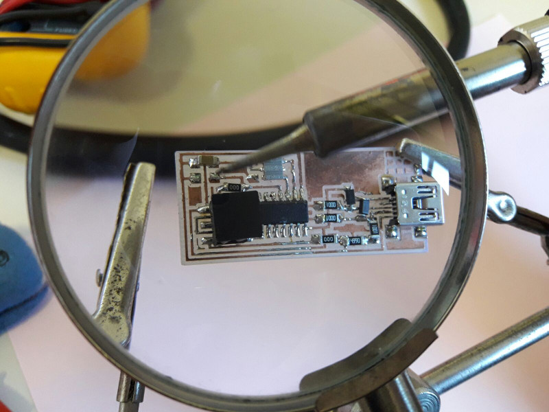
I had never soldered SMD components, and I'm still thinking that it's weird and a bit crazy. Anyway, using the soldering station of FabLab Mantova I placed and soldered a few components.
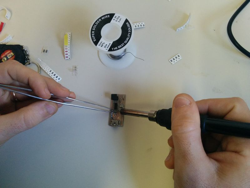
In this process a third hand tool with a magnifying glass was really useful!
I realized too late that I inverted the polarity of the two zener diodes. Stupid mistake! For some strange reasons, I put (deliberately) the white line next to the ground in both cases - since the line it is on the cathode side, the zeners were not working in the breakdown region and so the signals were not regulated to 3.3. Hence, I had to reverse the two diodes, hoping the ATtiny44 has not been fried in the meantime.
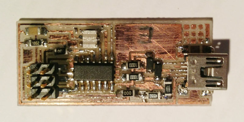
The results is quite horrible, but I've checked all resistors, capacitors and circuit continuity with my multimeter, and everything seems fine.
Programming the board
WARNING - you need a programmer to program the programmer. An Arduino will do the work for you.Open the Arduino IDE, then under File > Examples > ArduinoISP open the example code that will transform your Arduino into an In-System Programmer 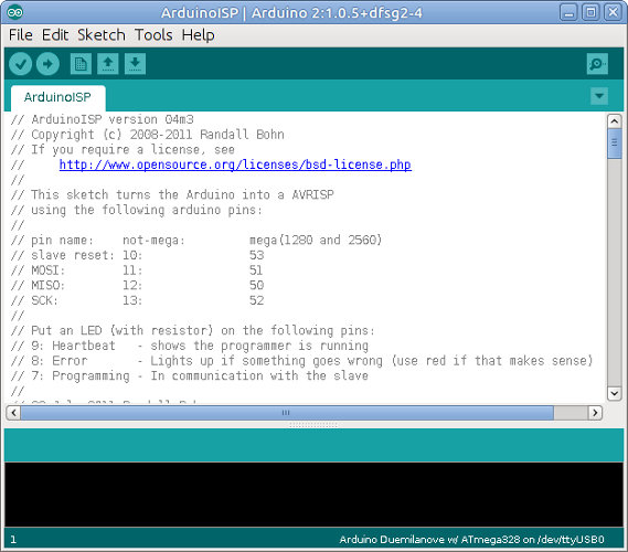 Then upload the code to your Arduino.
As you can see in the code, the sketch turns the Arduino into a AVRISP using the following Arduino pins:
- RST: 10
- MOSI: 11
- MISO: 12
- SCK: 13
- VCC: 5V
- GND: GND
So according to the code, connect Arduino to the FabISP 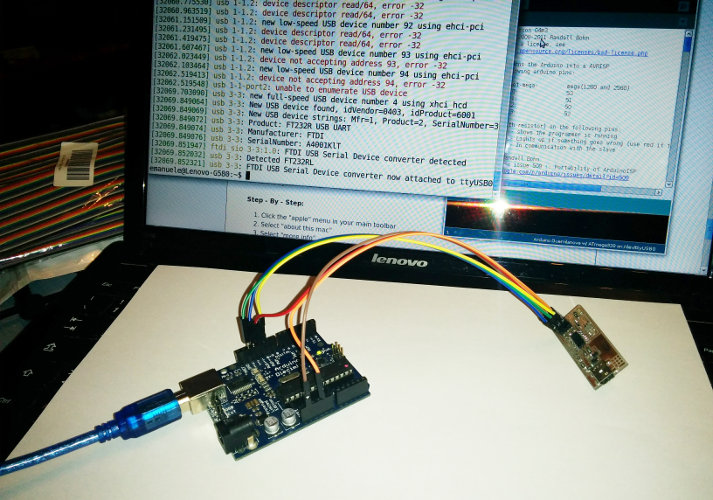
Following the instruction posted here, open a Terminal and install the required packages with
sudo apt-get install flex byacc bison gcc libusb-dev avrdude gcc-avr avr-libc libc6-dev build-essentialthen obtain the firmware with
cd /tmp
wget http://academy.cba.mit.edu/classes/embedded_programming/firmware.zip
unzip firmware.zip
cd fabISP_mac.0.8.2_firmware
then edit the Makefile and comment the lines
#AVRDUDE = avrdude -c usbtiny -p $(DEVICE) # edit this line for your programmer
AVRDUDE = avrdude -c avrisp2 -P usb -p $(DEVICE) # edit this line for your programmer
appending '#' at the beginning
#AVRDUDE = avrdude -c usbtiny -p $(DEVICE) # edit this line for your programmer
#AVRDUDE = avrdude -c avrisp2 -P usb -p $(DEVICE) # edit this line for your programmer
and set the correct programmer (check the name of the USB port, like /dev/ttyUSB0, with dmesg)
AVRDUDE = avrdude -c stk500v1 -b19200 -P /dev/ttyUSB0 -p $(DEVICE)Finally run
make clean && make hexand
sudo make fuseto program the microcontroller.
The fuses
- Using the Engbedded Atmel AVR® Fuse Calculator you can check the fuses setup for the ATtiny44A. The LOW setup 0XFF correspond to Ext. Crystal Osc >= 8.0 MHz, CKSEL=1111, SUT=11, while the 0xDF stands for HIGH enable Serial Program and Data Downloading. If you get
avrdude -c stk500v1 -b19200 -P /dev/ttyUSB0 -p attiny44 -U hfuse:w:0xDF:m -U lfuse:w:0xFF:m
avrdude: ser_open(): can't open device "/dev/ttyUSB0": Input/output error

avrdude done.  Thank you.

Makefile:119: recipe for target 'fuse' failed
make: *** [fuse] Error 1
emanuele@Lenovo-G580:/tmp/fabISP_mac.0.8.2_firmware$ sudo make fuse
avrdude -c stk500v1 -b19200 -P /dev/ttyUSB0 -p attiny44 -U hfuse:w:0xDF:m -U lfuse:w:0xFF:m
avrdude: stk500_getsync() attempt 1 of 10: not in sync: resp=0x15
avrdude: stk500_getsync() attempt 2 of 10: not in sync: resp=0x15


avrdude: stk500_getparm(): (a) protocol error, expect=0x14, resp=0x14

avrdude: stk500_getparm(): (a) protocol error, expect=0x14, resp=0x01
avrdude: stk500_initialize(): (a) protocol error, expect=0x14, resp=0x10
avrdude: initialization failed, rc=-1
         Double check connections and try again, or use -F to override
         this check.

avrdude: stk500_disable(): unknown response=0x12

avrdude done.  Thank you.

Makefile:119: recipe for target 'fuse' failed
make: *** [fuse] Error 1
try again after a few seconds. In the end you should finally see
avrdude -c stk500v1 -b19200 -P /dev/ttyUSB0 -p attiny44 -U hfuse:w:0xDF:m -U lfuse:w:0xFF:m

avrdude: AVR device initialized and ready to accept instructions

Reading | ################################################## | 100% 0.05s

avrdude: Device signature = 0x1e9207 (probably t44)
avrdude: reading input file "0xDF"
avrdude: writing hfuse (1 bytes):

Writing | ################################################## | 100% 0.02s

avrdude: 1 bytes of hfuse written
avrdude: verifying hfuse memory against 0xDF:
avrdude: load data hfuse data from input file 0xDF:
avrdude: input file 0xDF contains 1 bytes
avrdude: reading on-chip hfuse data:

Reading | ################################################## | 100% 0.02s

avrdude: verifying ...
avrdude: 1 bytes of hfuse verified
avrdude: reading input file "0xFF"
avrdude: writing lfuse (1 bytes):

Writing | ################################################## | 100% 0.06s

avrdude: 1 bytes of lfuse written
avrdude: verifying lfuse memory against 0xFF:
avrdude: load data lfuse data from input file 0xFF:
avrdude: input file 0xFF contains 1 bytes
avrdude: reading on-chip lfuse data:

Reading | ################################################## | 100% 0.02s

avrdude: verifying ...
avrdude: 1 bytes of lfuse verified

avrdude: safemode: Fuses OK (E:FF, H:DF, L:FF)

avrdude done.  Thank you.
And then
make programshould result in
avrdude -c stk500v1 -b19200 -P /dev/ttyUSB0 -p attiny44 -U flash:w:main.hex:i

avrdude: AVR device initialized and ready to accept instructions

Reading | ################################################## | 100% 0.05s

avrdude: Device signature = 0x1e9207 (probably t44)
avrdude: NOTE: "flash" memory has been specified, an erase cycle will be performed
         To disable this feature, specify the -D option.
avrdude: erasing chip
avrdude: reading input file "main.hex"
avrdude: writing flash (1986 bytes):

Writing | ################################################## | 100% 3.40s

avrdude: 1986 bytes of flash written
avrdude: verifying flash memory against main.hex:
avrdude: load data flash data from input file main.hex:
avrdude: input file main.hex contains 1986 bytes
avrdude: reading on-chip flash data:

Reading | ################################################## | 100% 2.35s

avrdude: verifying ...
avrdude: 1986 bytes of flash verified

avrdude: safemode: Fuses OK (E:FF, H:DF, L:FF)

avrdude done.  Thank you.

avrdude -c stk500v1 -b19200 -P /dev/ttyUSB0 -p attiny44 -U hfuse:w:0xDF:m -U lfuse:w:0xFF:m

avrdude: AVR device initialized and ready to accept instructions

Reading | ################################################## | 100% 0.05s

avrdude: Device signature = 0x1e9207 (probably t44)
avrdude: reading input file "0xDF"
avrdude: writing hfuse (1 bytes):

Writing | ################################################## | 100% 0.02s

avrdude: 1 bytes of hfuse written
avrdude: verifying hfuse memory against 0xDF:
avrdude: load data hfuse data from input file 0xDF:
avrdude: input file 0xDF contains 1 bytes
avrdude: reading on-chip hfuse data:

Reading | ################################################## | 100% 0.02s

avrdude: verifying ...
avrdude: 1 bytes of hfuse verified
avrdude: reading input file "0xFF"
avrdude: writing lfuse (1 bytes):

Writing | ################################################## | 100% 0.02s

avrdude: 1 bytes of lfuse written
avrdude: verifying lfuse memory against 0xFF:
avrdude: load data lfuse data from input file 0xFF:
avrdude: input file 0xFF contains 1 bytes
avrdude: reading on-chip lfuse data:

Reading | ################################################## | 100% 0.02s

avrdude: verifying ...
avrdude: 1 bytes of lfuse verified

avrdude: safemode: Fuses OK (E:FF, H:DF, L:FF)

avrdude done.  Thank you.
After you have programmed the board, unplug Arduino, disconnect the wires and plug the FabISP into the USB port. Type
lsusb
If your FabISP has been successfully programmed, you should see it into the list of USB connected device:
emanuele@Lenovo-G580:~$ lsusb
...
Bus 001 Device 001: ID 1d6b:0002 Linux Foundation 2.0 root hub
Bus 004 Device 001: ID 1d6b:0003 Linux Foundation 3.0 root hub
Bus 003 Device 123: ID 1781:0c9f Multiple Vendors USBtiny       <---- it works!!!!
Bus 003 Device 001: ID 1d6b:0002 Linux Foundation 2.0 root hub
...
Once the FabISP has been programmed, you can remove the two 0 ohm resistors
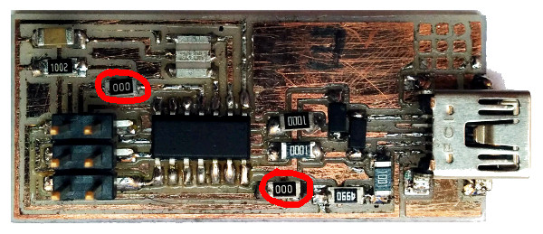 and the FabISP is now ready to be used for programming other boards.
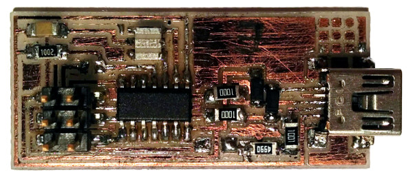
Download zone - List of files
- fabisp_fw.tar.gz - GNU GPLv2 FabISP firmware (© David A. Mellis, Dick Streefland and Christian Starkjohann 2006-2009)
- fabisp_traces.zip - FabISP traces in PNG and Roland MX-40 RML formats (© David A. Mellis and Neil Gershenfeld)