Exercise 4: Electronics Production
Assignment 4: Make an in-circuit programmer based on the AtTiny44 by milling the PCB.
How to export the file using FabModules
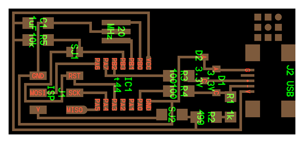
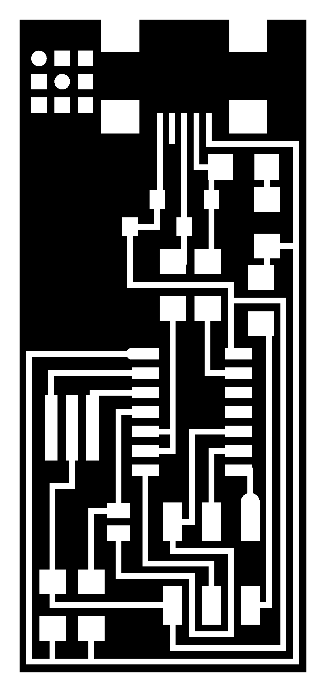
Enrico by Opendot suggested us to start with the version based on the ceramic resonator, so I used the hello-ISP-44-res (Fig. 0) version of board available on the Week 4 - Electronic production page.
First I downloaded the high-resolution version of the PCB (both the trace and the interior images) from the FabAcademy archive.
Then, I opened fabmodules, I imported the PNG trace image, I set the Roland mill .rml output and the PCB trace (1/64).
At this point I selected the MDX-40 machined and fabmodules completed the field with the default settings. You can leave them, but you should alway check them. First, I set x0,y0,z0 all to 0, so that the zero of the image is the homing point of the machine, and zhome to 10 to move away the tool at the end of the milling process. Then, I lowered the speed of the machine to 2 mm/s (this could help fragile path to last). The default cut depth of 0.1 mm is fine, but we can change it slightly to 0.08 to reduce the wear of the tools. I left the default number of offsets (4) and set the diameter of the tool to 0.4. This tool is very expensive and should be handled with care! Finally, I set the number of offsets to 2 and I clicked on "Calculate the path" and I saved to result.
I downloaded my traced .rml files and I moved to the milling machine!
How to use the milling machine
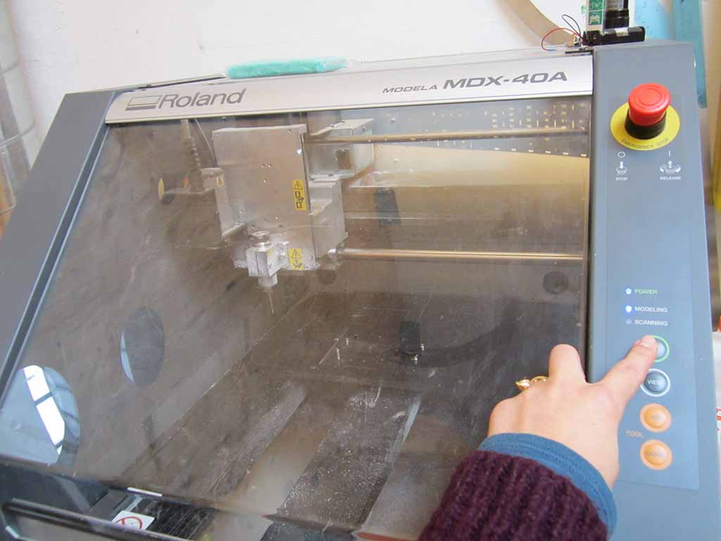
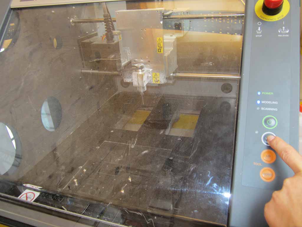
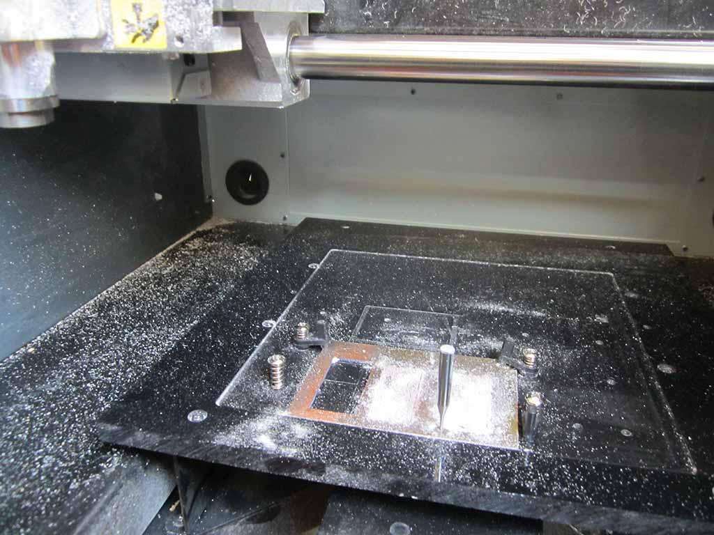
First, I cleaned up the machine table, I switched on the machine (Fig. 1) and clicked on View to move the plate (Fig. 2).
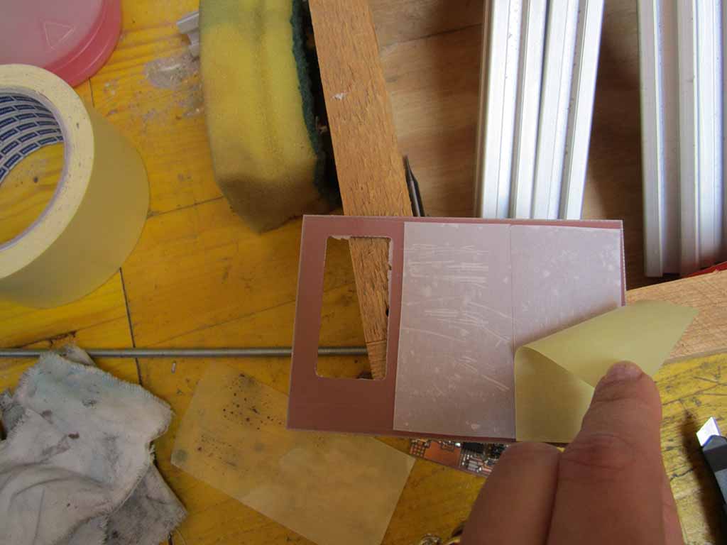
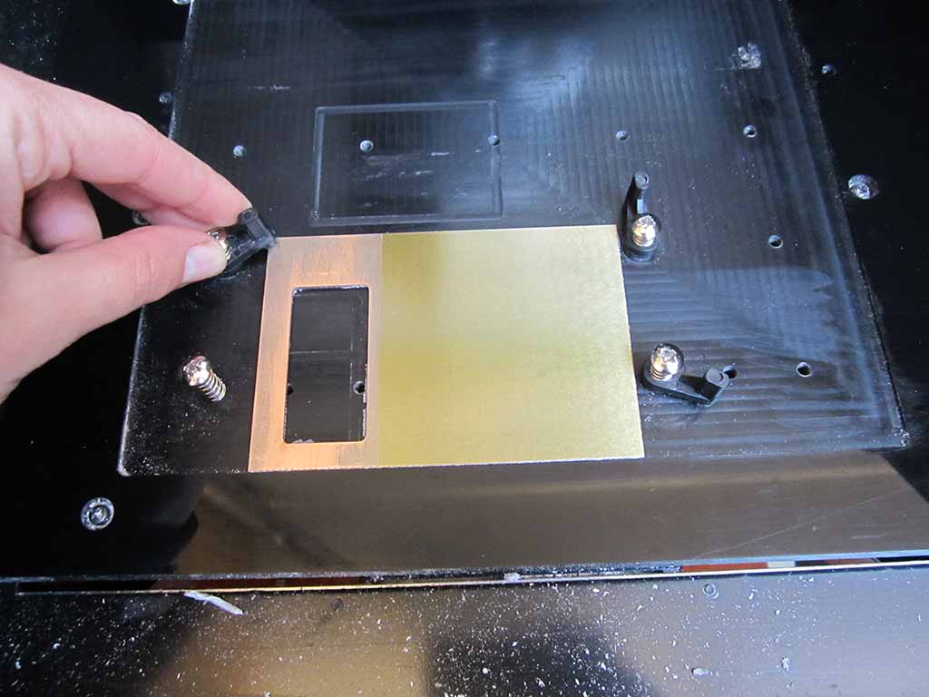
Then I fixed the copper plate on the mill table using double-sided tape (Fig. 3 and 4), and I changed the endmill putting a piece of rubber under the spindle to save the endmill in case it falls down (Fig. 5).
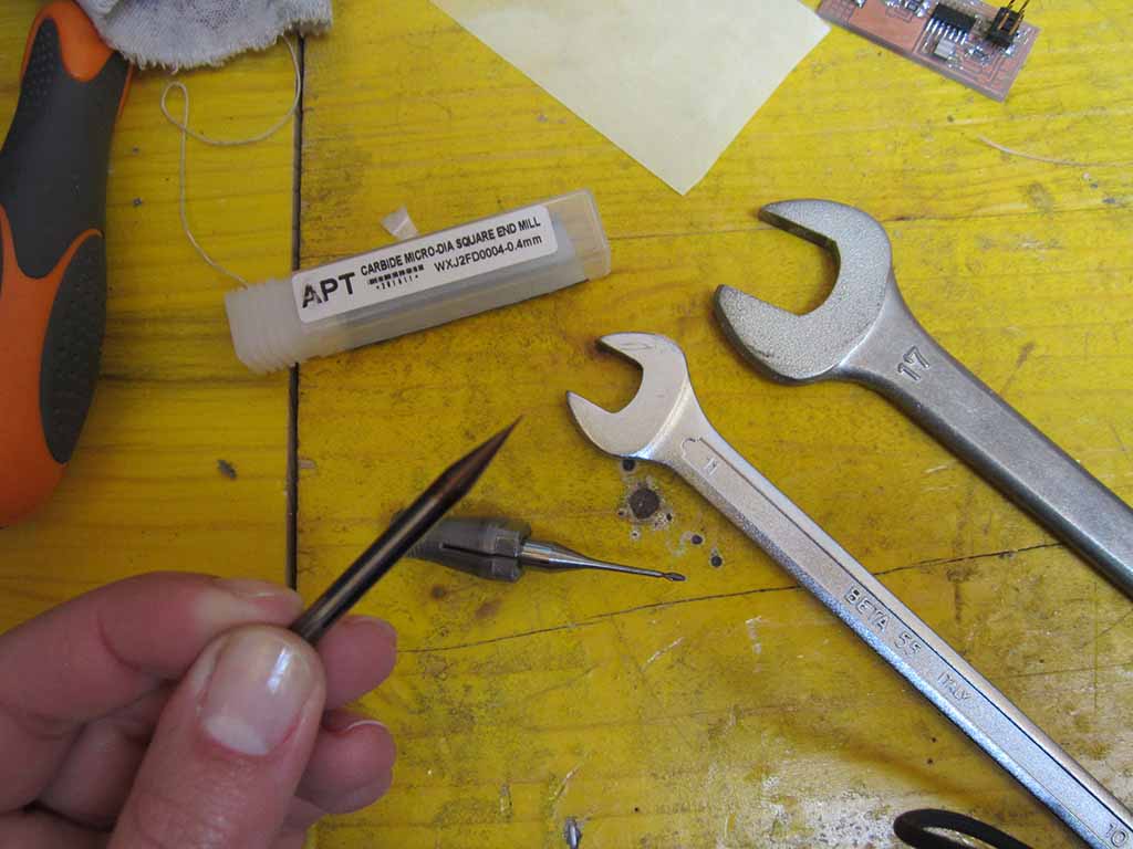
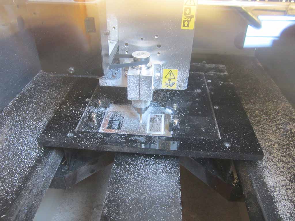
I used a 0.4 mm tool (Fig. 6).
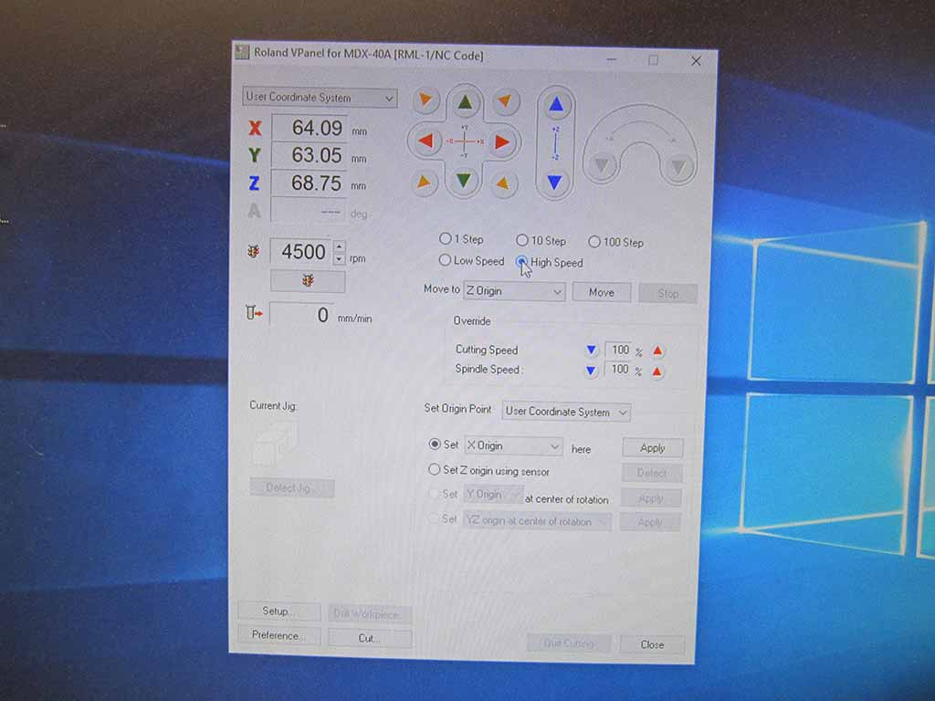
At this point, I opened the vPanel software and set the XYZ origins (Fig. 7).
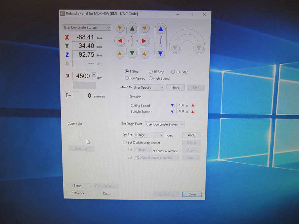
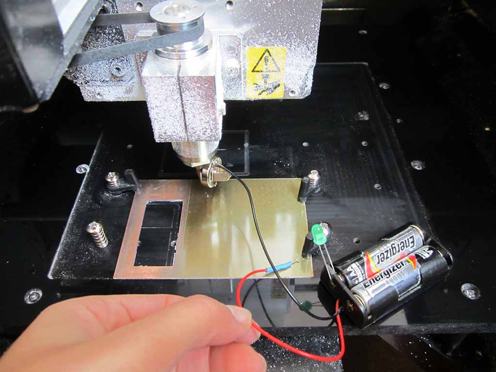
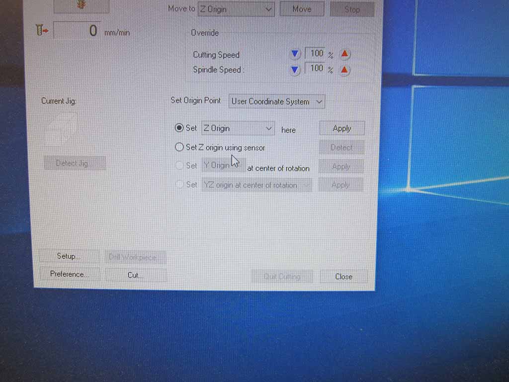
First I set the zero of the Z axis moving it carefully (really carefully!): during this phase the endmill should descend with 0.1 mm steps and stopped when it brush against the copper layer (Fig. 8).
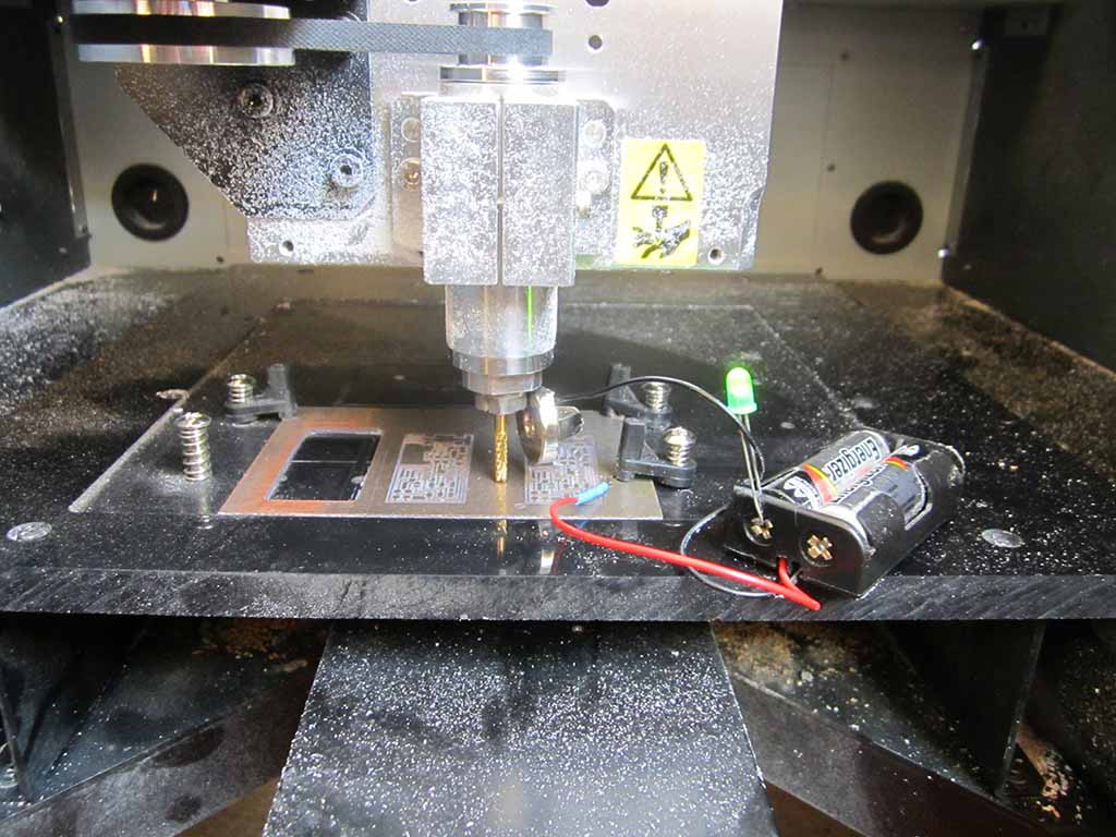
During this phase you can use a simple led-based circuit: when the tool touches the copper, the circuit is closed and the led lights on (Fig. 9).
Then, I set moved up again the tool, moved it to the XY origin and set the coordinates as the new XY zero (Fig. 10).
We are almost ready: I moved up the Z axis a bit (to not scratch the board), set the new Z home, clicked on "Cut", loaded my .RML file and started to mill. I know, I was cutting the air, but this step is useful to check the the XY origin are correct.
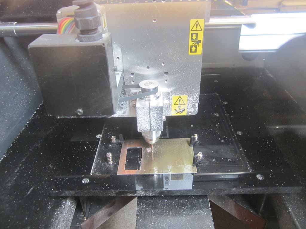
I spread a bit of oil on the board (not on the border or it could ruin the fixing tape) to make the endmill move smootly and to reduce the dust. Then, I set the spindle speed to 15000 rpm, I loaded my .RML file and started to mill (Fig. 11).
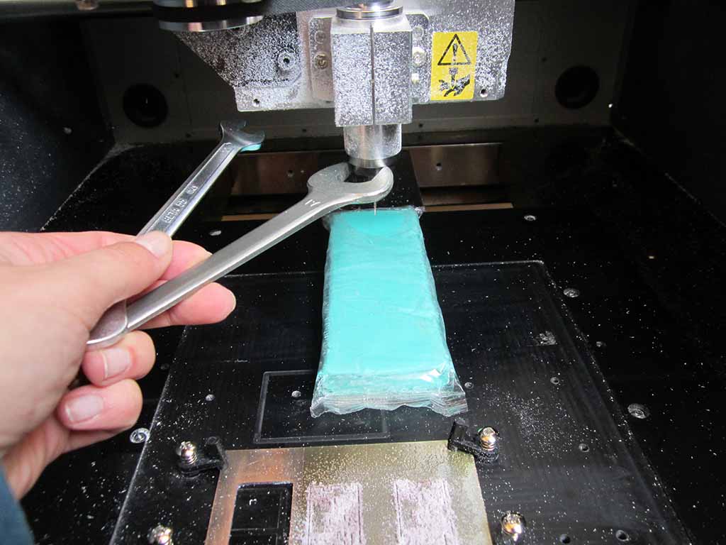
I moved down the tool to the correct Z and I launch the cut again (Fig. 12).
How to broke a tool
The first cut went fine, so I repeated the process on fabmodules for the cutout image; this time I set Outline cut to 1/32, Cut depth to 0.75 mm, Stock thickness to 1.5 mm and Tool diameter to 1.5 mm, and only 1 for the offset.
At this point I swapped the endmill with the 1.5 mm and I launched the cut with the new outline code.
The machine started to move to the origin and the mill started to go down, down and... too late! I forgot to reset the Z origin after having changed the endmill: since the new tool was taller, the Z axis messed up. So the tip of the tool punctured the plate and stuck into the table (Fig. 13).
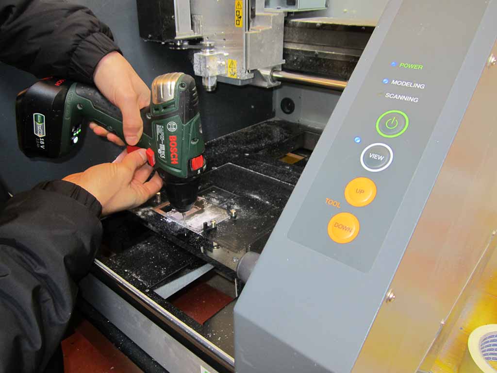
I had to stop everything, use a drill (Fig. 14) to get the endmill out and in the end the endmill broke :-(
How to set up the file using vCarve
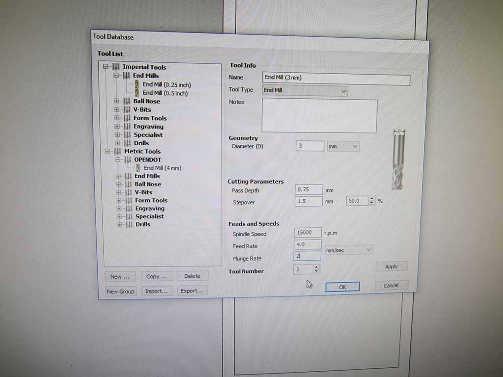
Unfortunately, the broken endmill was the last one with the 1.5mm diameter. So, I had to mount a 3mm tool, set up the Z axis (Fig. 14), go back to fabmodules, change the tool diameter and... another issue arose! The diameter was too big for the drawing and fabmodules was not able to generate the correct .rml cut file for the machine. I was stuck, but Tiziano by Opendot helped me suggesting to convert the PNG file to dxf using Illustrator and then edit it in vCarve Pro (Fig. 15).
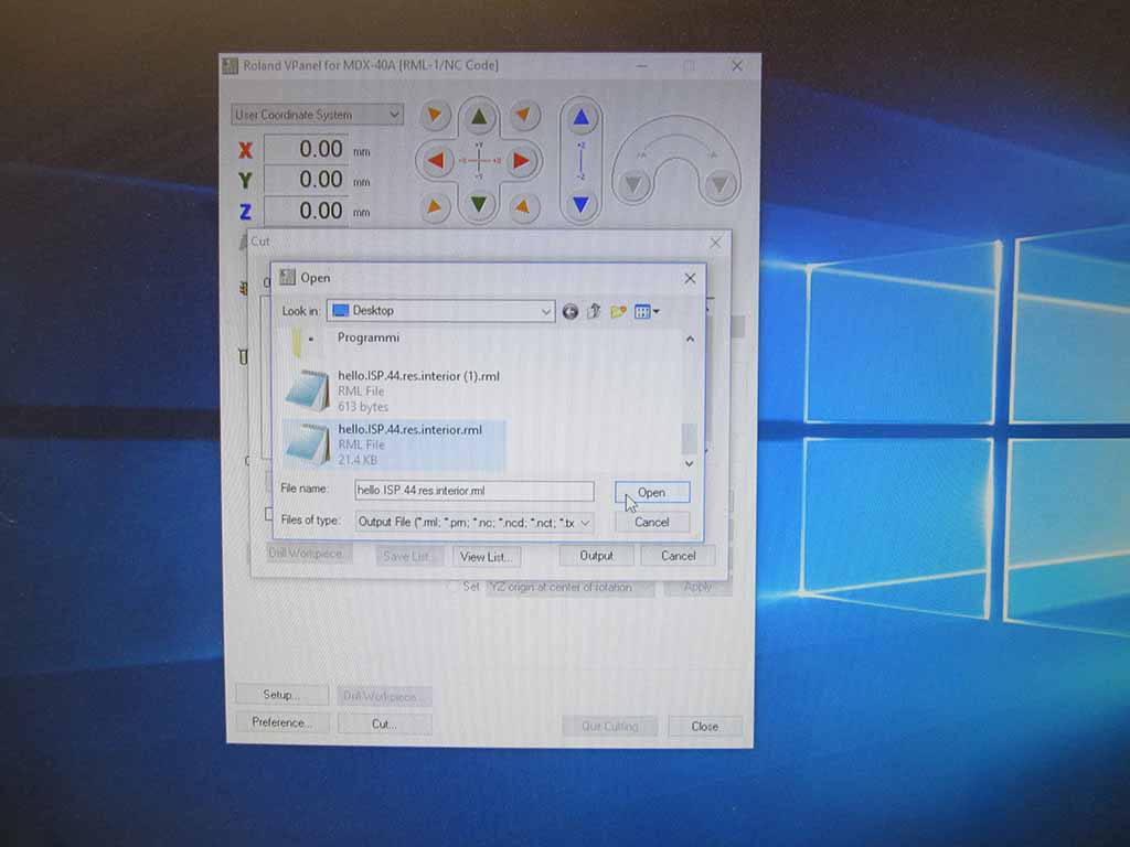
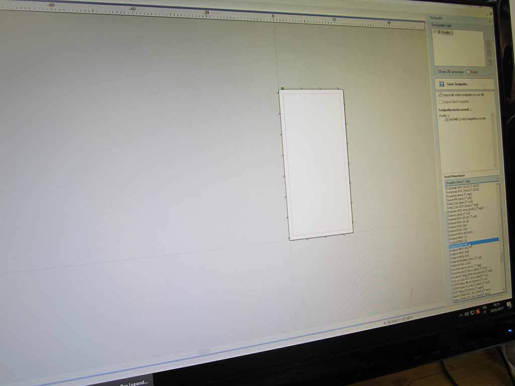
Luckly, vCarve software successfully generated to cut file (Fig. 16), so I finally saved it and imported in vPanel (Fig. 17 and 18).
After a stupid mistake, a broken endmill and three hours lost, I think I have learned one important lesson: redo the zeroing of the Z axis after each endmill change!
How to solder the PCB
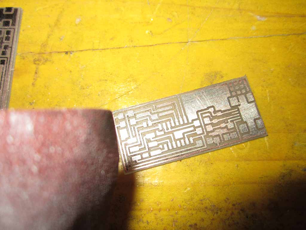
The pcb came out good and flawless. I rubbed the surface with a piece of sandpaper to clean it and remove the small and unwanted copper pieces remained on the PCB (Fig. 19).
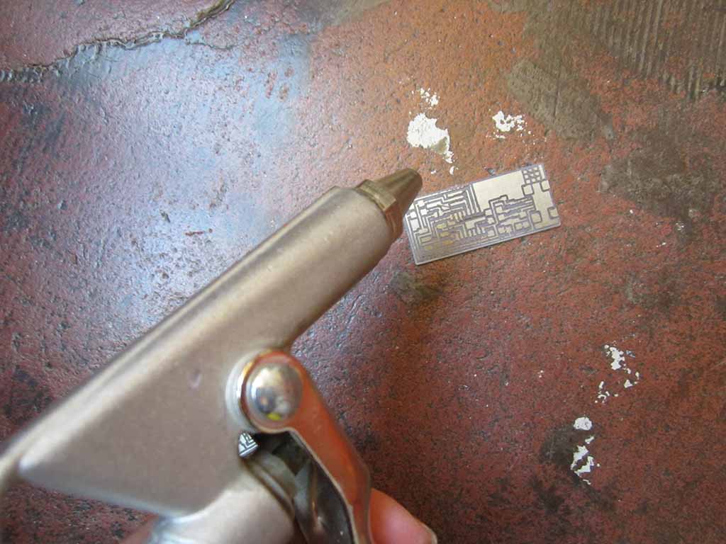
Finally I removed all dust with an air blow gun (Fig. 20).
Before starting to solder, I collected all the materials needed to completed the circuit (all already available at OpenDot - thanks Enrico!):
- 2 100Ω Resistors
- 2 100kΩ Resistors
- 1 kΩ Resistor
- 1 499Ω Resistor
- 2 0Ω Resistors (Jumpers)
- 1uF Capacitor
- 2 Zener Diodes
- 1 20MHz Resonator
- 1 ATTiny44
- 1 USB connector
- 6 Pin headers
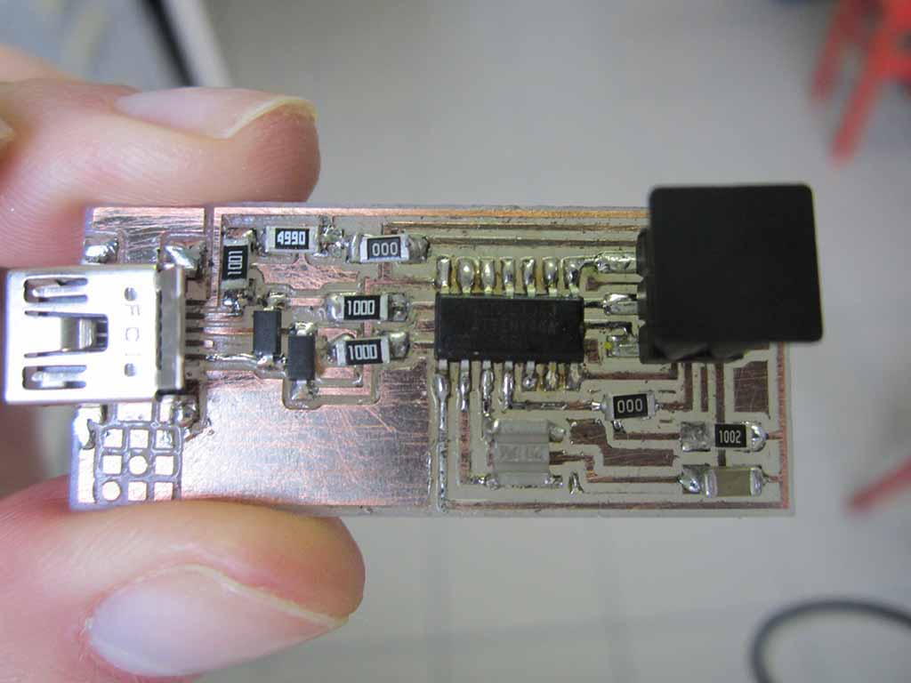
Using a soldering station, a bit of tin-lead solder and a lot of patience, I placed and soldered all components (Fig. 21).
How to program the PCB
I had some problems with this phase: first time I soldered the resonator in the wrong way because it creates a short circuit; second I didn't use a programmer to program the Fab ISP.
I decided to use Arduino to program the Fab ISP. first of all I trasformed Arduino in a In-System Programmer opening "Arduino IDE" and going into "Example" and "Arduino ISP".
At this point I uploaded the code to Arduino turning it into a AVRISP with these pins:
RST: 10
MOSI: 11
MISO: 12
SCK: 13
VCC: 5V
GND: GND
So I connected Arduino to the FabISP, followed this instructions, opened a Terminal and installed the needed packages with
sudo apt‐get install flex byacc bison gcc libusb‐dev avrdude gcc‐avr avr‐libc libc6‐dev build‐essential
Then I downloaded and acquired the firmware
        cd/tmp
        wget http://academy.cba.mit.edu/classes/embedded_programming/firmware.zip
        unzip firmware.zip
        cd fabISP_mac.0.8.2_firmware
and edited the Makefile adding # at the beginning
        #AVRDUDE = avrdude ‐c usbtiny ‐p $(DEVICE) # edit this line for your programmer
        #AVRDUDE = avrdude ‐c avrisp2 ‐P usb ‐p $(DEVICE) # edit this line for your programmer
I setting these parameters:
AVRDUDE = avrdude ‐c stk500v1 ‐b19200 ‐P /dev/ttyUSB0 ‐p $(DEVICE)
and launched these command to programm the microcontroller
        make clean && make hex
        sudo make fuse
Finally this message appeared on the computer
        avrdude ‐c stk500v1 ‐b19200 ‐P /dev/ttyUSB0 ‐p attiny44 ‐U hfuse:w:0xDF:m ‐U lfuse:w:0xFF:m
        avrdude: AVR device initialized and ready to accept instructions

        Reading | ################################################## | 100% 0.05s

        avrdude: Device signature = 0x1e9207 (probably t44)
        avrdude: reading input file "0xDF"
        avrdude: writing hfuse (1 bytes):

        Writing | ################################################## | 100% 0.02s

        avrdude: 1 bytes of hfuse written
        avrdude: verifying hfuse memory against 0xDF:
        avrdude: load data hfuse data from input file 0xDF:
        avrdude: input file 0xDF contains 1 bytes
        avrdude: reading on‐chip hfuse data:

        Reading | ################################################## | 100% 0.02s

        avrdude: verifying ...
        avrdude: 1 bytes of hfuse verified
        avrdude: reading input file "0xFF"
        avrdude: writing lfuse (1 bytes):

        Writing | ################################################## | 100% 0.06s

        avrdude: 1 bytes of lfuse written
        avrdude: verifying lfuse memory against 0xFF:
        avrdude: load data lfuse data from input file 0xFF:
        avrdude: input file 0xFF contains 1 bytes
        avrdude: reading on‐chip lfuse data:

        Reading | ################################################## | 100% 0.02s

        avrdude: verifying ...
        avrdude: 1 bytes of lfuse verified

        avrdude: safemode: Fuses OK (E:FF, H:DF, L:FF)

        avrdude done.  Thank you.
So I typed "Make program" and it appeared
        avrdude ‐c stk500v1 ‐b19200 ‐P /dev/ttyUSB0 ‐p attiny44 ‐U flash:w:main.hex:i

        avrdude: AVR device initialized and ready to accept instructions

        Reading | ################################################## | 100% 0.05s

        avrdude: Device signature = 0x1e9207 (probably t44)
        avrdude: NOTE: "flash" memory has been specified, an erase cycle will be performed
        To disable this feature, specify the ‐D option.
        avrdude: erasing chip
        avrdude: reading input file "main.hex"
        avrdude: writing flash (1986 bytes):

        Writing | ################################################## | 100% 3.40s

        avrdude: 1986 bytes of flash written
        avrdude: verifying flash memory against main.hex:
        avrdude: load data flash data from input file main.hex:
        avrdude: input file main.hex contains 1986 bytes
        avrdude: reading on‐chip flash data:

        Reading | ################################################## | 100% 2.35s

        avrdude: verifying ...
        avrdude: 1986 bytes of flash verified

        avrdude: safemode: Fuses OK (E:FF, H:DF, L:FF)

        avrdude done.  Thank you.

        avrdude ‐c stk500v1 ‐b19200 ‐P /dev/ttyUSB0 ‐p attiny44 ‐U hfuse:w:0xDF:m ‐U lfuse:w:0xFF:m

        avrdude: AVR device initialized and ready to accept instructions

        Reading | ################################################## | 100% 0.05s

        avrdude: Device signature = 0x1e9207 (probably t44)
        avrdude: reading input file "0xDF"
        avrdude: writing hfuse (1 bytes):

        Writing | ################################################## | 100% 0.02s

        avrdude: 1 bytes of hfuse written
        avrdude: verifying hfuse memory against 0xDF:
        avrdude: load data hfuse data from input file 0xDF:
        avrdude: input file 0xDF contains 1 bytes
        avrdude: reading on‐chip hfuse data:

        Reading | ################################################## | 100% 0.02s

        avrdude: verifying ...
        avrdude: 1 bytes of hfuse verified
        avrdude: reading input file "0xFF"
        avrdude: writing lfuse (1 bytes):

        Writing | ################################################## | 100% 0.02s

        avrdude: 1 bytes of lfuse written
        avrdude: verifying lfuse memory against 0xFF:
        avrdude: load data lfuse data from input file 0xFF:
        avrdude: input file 0xFF contains 1 bytes
        avrdude: reading on‐chip lfuse data:

        Reading | ################################################## | 100% 0.02s

        avrdude: verifying ...
        avrdude: 1 bytes of lfuse verified

        avrdude: safemode: Fuses OK (E:FF, H:DF, L:FF)

        avrdude done.  Thank you.
Now the Fab ISP is a programmer and we can disconnect Arduino and use it.
Download area
Download Neil's file for FabISP traces
Download Neil's file for FabISP edge