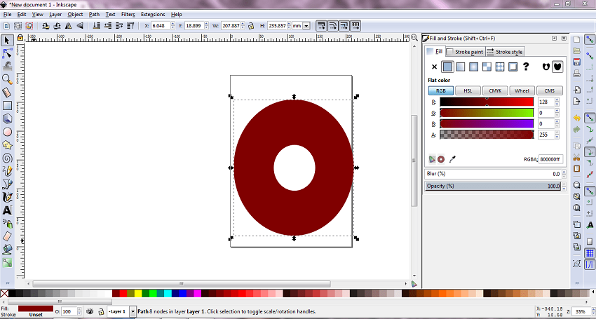
In 2D modelling I was using inkscape software.Firstly, I was searching for this software on google. Then I found the inkscape sofware for windows - 64 bits.According to Wikipedia Inkscape is a free and open-source vector graphics editor; it can be used to create or edit vector graphics such as illustrations, diagrams, line arts, charts, logos and complex paintings. Inkscape's primary vector graphics format is Scalable Vector Graphics (SVG), however many other formats can be imported and exported. Inkscape can render primitive vector shapes (e.g. rectangles, ellipses, polygons, arcs, spirals, stars and 3D boxes) and text. These objects may be filled with solid colors, patterns, radial or linear color gradients and their borders may be stroked, both with adjustable transparency. Embedding and optional tracing of raster graphics is also supported, enabling the editor to create vector graphics from photos and other raster sources. Created shapes can be further manipulated with transformations, such as moving, rotating, scaling and skewing.
Firtly I was choose exe-installer,then I download that file.

step:2
After downloding inkscape software I installed it in my windows.Then I took help of google and youtube for how to draw sketch in inkscape.After reading inkscape tutorial which is inside the software ,I got basic information of inkscape.Then I was playing with shapes.
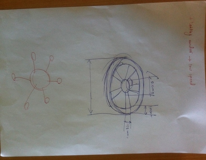
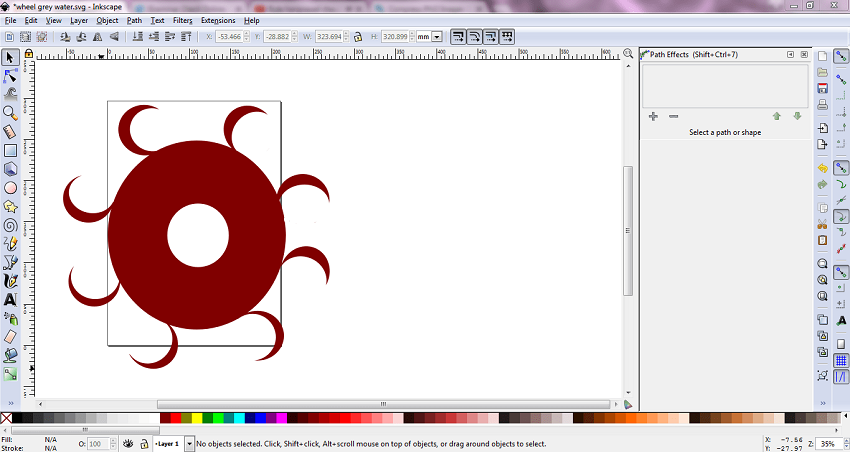
my free hand sketch
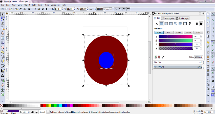
Then I insert circle on red circle
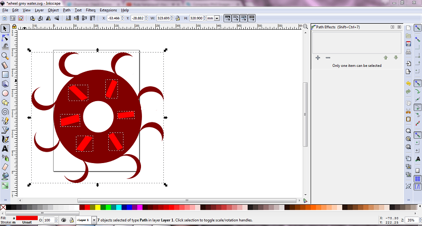
After that I was going through following steps i.e.,-path-difference
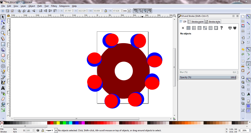
Then I choose circle one by one and simultanuosly - path- difference.
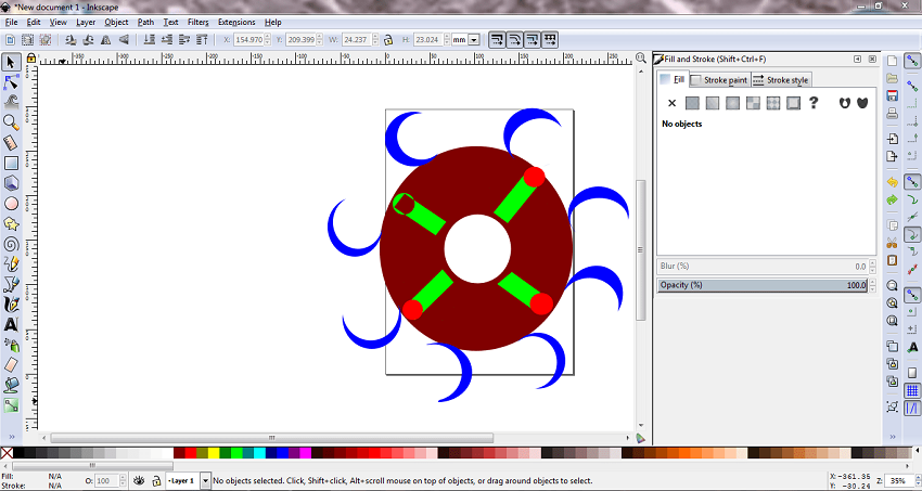
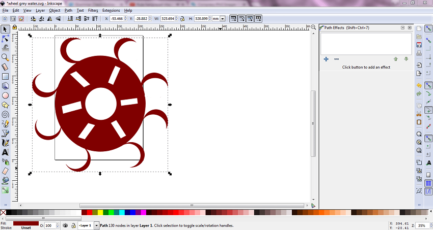
After that I was removing that rectangles and apply union command by selecting whole body.
Then I draw rectangle and duplicate it using duplicate command.Then I rotated that rectangles using double right click of mouse.
3D modelling
In 3D modelling I was using catia and solidworks too.But comparatively I realiza that catia V5 software is best!According to Wikipedia CATIA is the worlds engineering and design leading software for product 3D CAD design excellence.It is used to design, simulate, analyze, and manufacture products in a variety of industries including aerospace, automotive, consumer goods, and industrial machinery, just to name a few. It addresses all manufacturing organizations, from OEMs through their supply chains, to small independent producers.
If you stop and take a look around, CATIA is everywhere. CATIA is in the plane that just flew over, the car that just went silently by, the phone you just answered, and the bottle of water that you just finished.
And SolidWorks is a solid modeler, and utilizes a parametric feature-based approach to create models and assemblies. The software is written on Parasolid-kernel. Parameters refer to constraints whose values determine the shape or geometry of the model or assembly. Parameters can be either numeric parameters, such as line lengths or circle diameters, or geometric parameters, such as tangent, parallel, concentric, horizontal or vertical, etc. Numeric parameters can be associated with each other through the use of relations, which allows them to capture design intent.
So after installing catia v5 and solidworks student licence copy, I was starting to draw my project drawing
Firstly I was playing with catia v5.
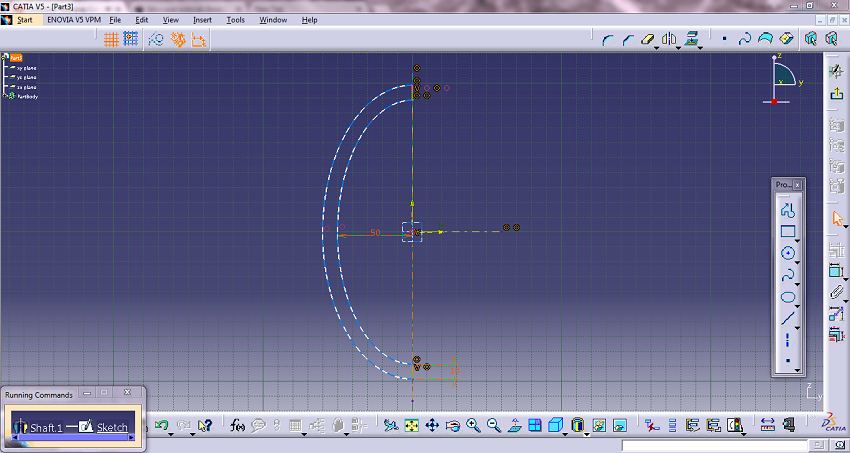
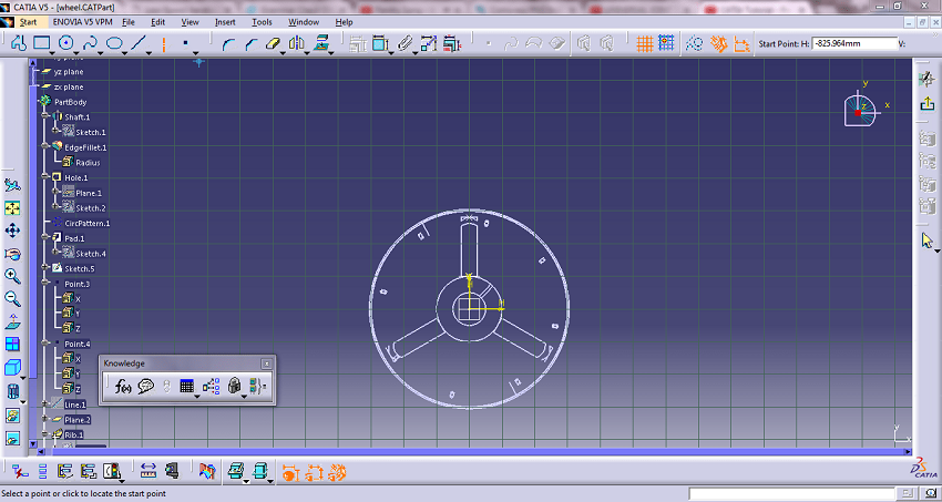
I went to star-mechanical part-shaft command-sketcher-workbench-draw a arc-then define axis-dimensioning-geometry turns in green color,that's mean it is constrained-exit sketch-select axis-define degree of rotation i.e.,180-ok-procedure done.
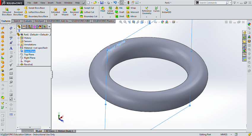
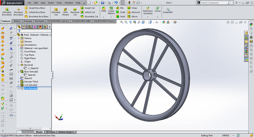
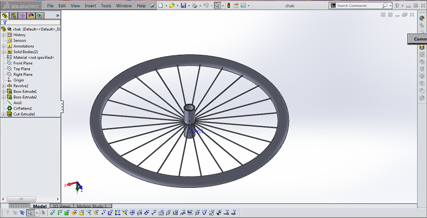
Then I went to solidworks,my aim is to create a wheel.Firsly I was doing rough work like what should be dimensions and what is the general procedure will be require that kind of stuff.In catia v5 ,command naming is shaft that command name in solidworks is revolve boss.And other like wise in catia and solidworks is pad i.e,extruded boss,pocket i.e.,extruded cut,rib command same in both.
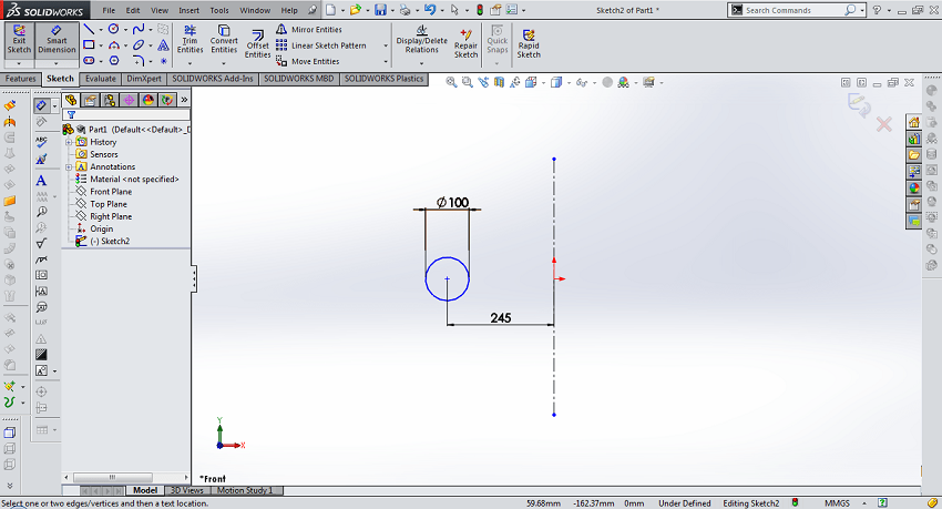
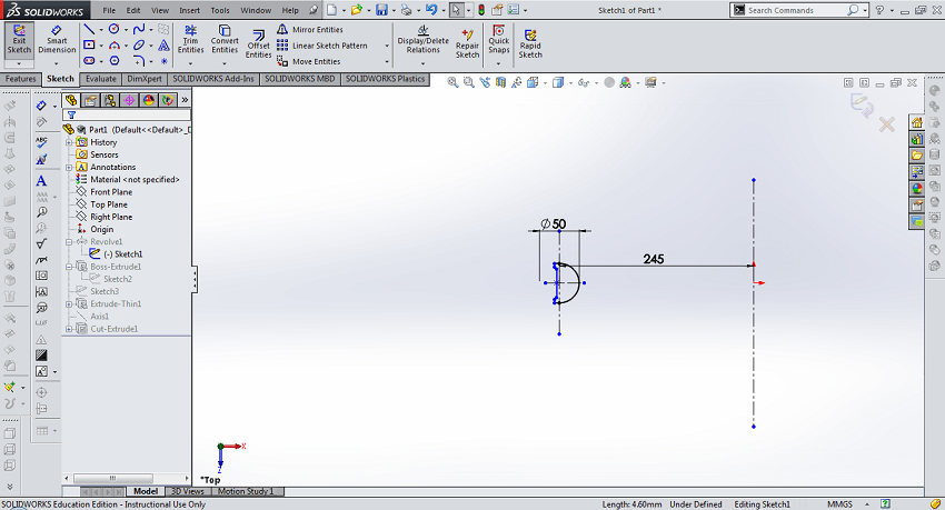
Firstly I was selecting top plane and converting it into normal plane.Then I went to sketch part,after that I draw circle which is offset from the origin.Then I draw axis from the origin,then I gave dimensions.When I define its axis the whole geometry converting into black color.then I went to features and by selecting revolve boss with axis round wheel apears.
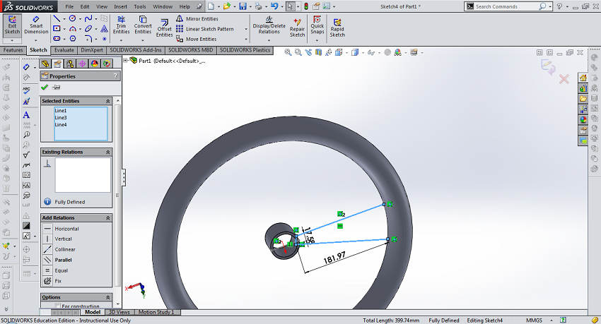
then I went to sketch and edit sketch like this,
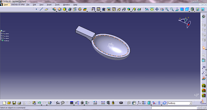
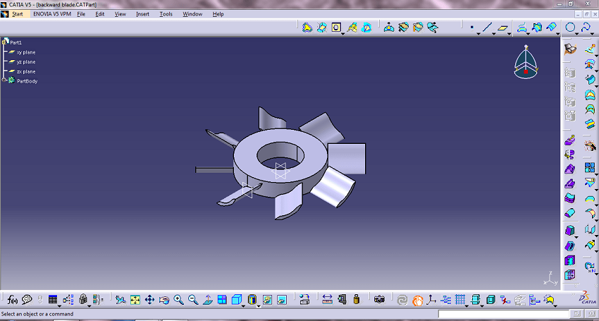
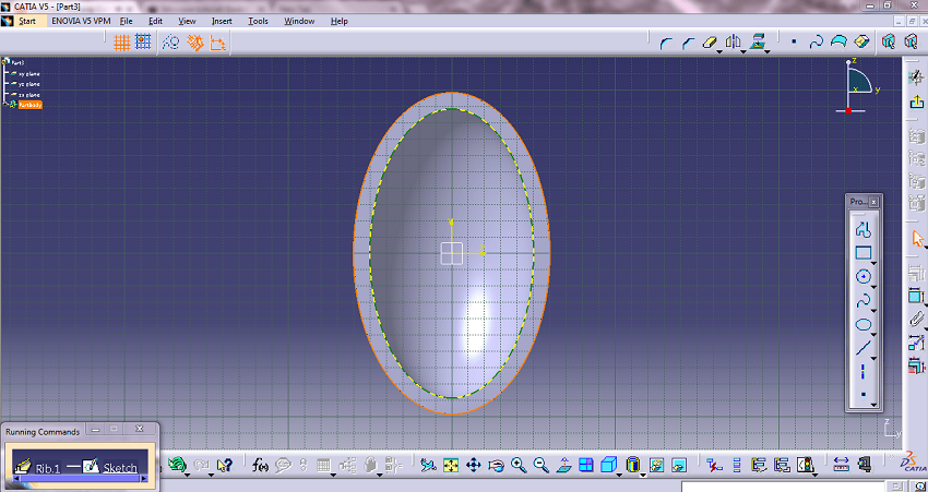
In catia I was drawn handle of the bucket by creating another plane taking reference plane.Then I draw profile by selecting that.Then using pad command I fill material in it.
As simillar procuder that I was mentionig during solidworks that same steps followed during catia drawing.
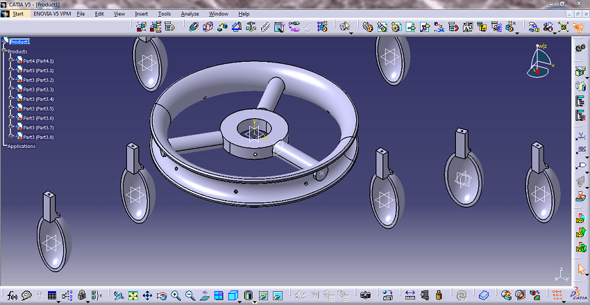
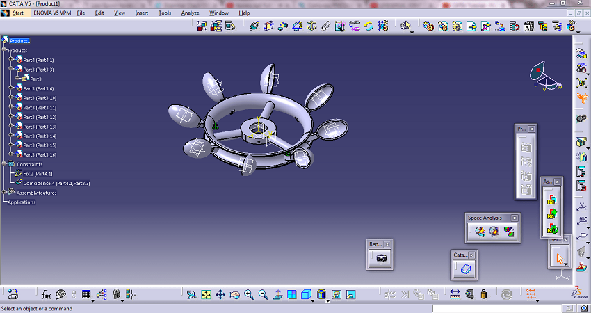
Then I went to assemby in catia.I call existing part on the work bench.Firstly I fixed that wheel by giving constrained.Then I select bucket part and gave circular constrain.Then run it.After that I went to circular pattern.There is dialogue box apears in that I edit intences and degree for this.After that I click apply and ok button.
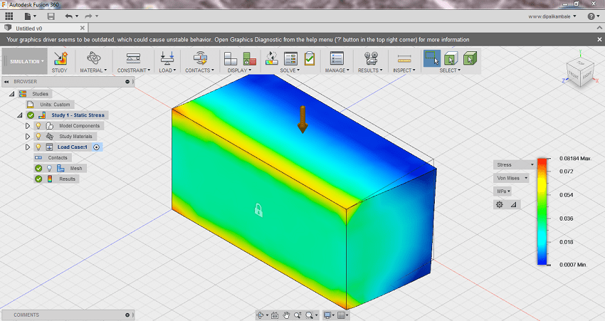
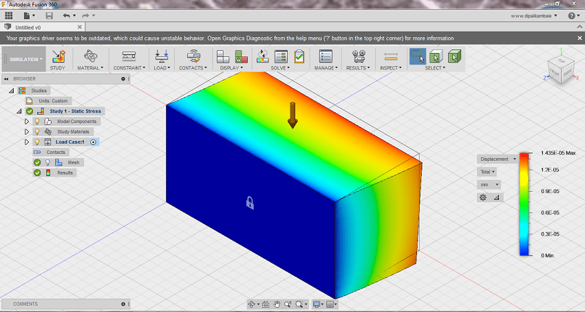
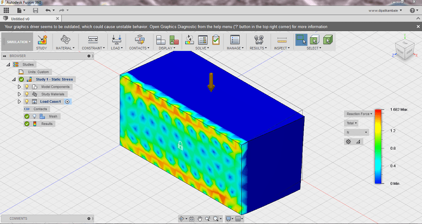
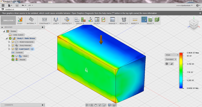
According to google Fusion 360 is the first 3D CAD, CAM, and CAE tool of its kind. It connects your entire product development process in a single cloud-based platform that works on both Mac and PC.It is really good in simulation and animation too.I just take cube for the simulation purpose.Firstly I draw a geometry in fusion 360. After that I was going to the simulation.Then I select static simulation.Then click on study.I fixed the body at one side by using lock constrain.Then I apply 50 N load and say ok