Week 13: Input Devices
Assignment:
- Measure something: add a sensor to a microcontroller board that you have designed and read it.
This week goal is to fabricate a board adding an input device and program it.
Machines:
- Trotec Speedy 300
- Soldering heat gun
Software:
Components:
- 6 pin ISP connector
- 6 pin FTDI connector
- 1 ATtiny 45
- 1 Sonar HC-SR04
- 1 Resistor 10K
- 1 Capacitor 1uF
I decided to use a sonar for this assignment because I’ll use in my project a water level sensor and I wanted to try measuring distance.
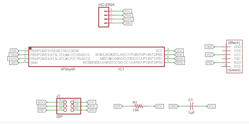
I used Neil’s sonar files to construct my board. I made the board and schematic in Eagle.
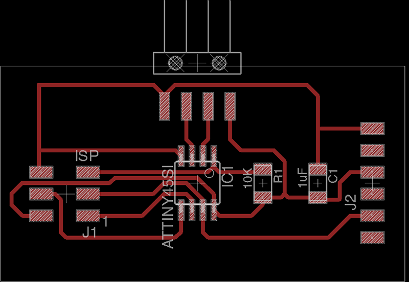
To fabricate and construct my board, I did the same as my previous electronics assignments, I used a stencil cut in Laser Trotec Speedy 300 to paint the traces and etch in ferric per chloride.
I solder the components using soldering paste and a heat gun.
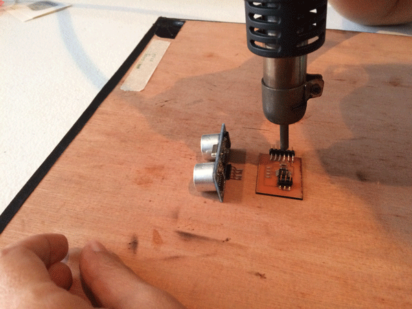
This is my board finished:

Once I finish the soldering process I test the board to be sure everything works well and I proceed to connect the board with the FabISP, and then I connect the mini USB and FTDI cables to my computer to start to programming the board.

Doign that I start to program it with Make and using my FabISP board following the next steps:
- Download Nei’s .c and .make files.
- Open Terminal located in Applications folder and change directory to the folder where saved the .c and .make files.
- In Terminal command “make -f hello.HC-SR04.makefile program-usbtiny” to upload the C program to the board.

To visualice Python sonar interface I used Terminal following this steps :
- Download Nei's py file.
- Command “sudo easy_install pyserial” to install pyserial and be able to see the window interface.
- Command “python hello.HC-SR04.py /dev/tty.usbserial-FT9L3CI0” and the window interface appear the screen.

And here is a short video showing how the sonar works.
SONAR HC-SR04 from Damaris Cotto on Vimeo.
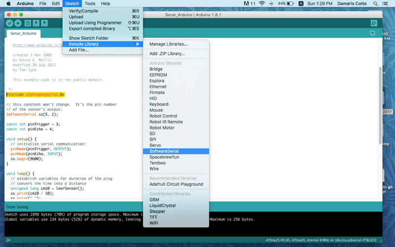
Now is time to see the sonar working on Arduino IDE serial monitor. To do that first I used the Ping sketch under File - Examples - 06 Sensors menu.

Then I had to include the softwre serial library to be able to choose the pins on the ATtiny 45, because the example was designed to use it with an Arduino board.
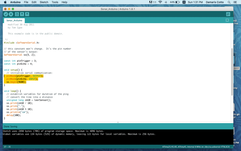
To set the pins numbers I had to check in the board which one corresponds to Tx and Rx pins of the FTDI connector to the ATtiny 45. Tx corresponds to the pin number 5 and Rx isn't connectec so, my instructor suggestion was declare it is connected to RST even though phisicaly is connected to nothing. Then I declare where the sonar pins are connected to, in this case Trigger is connected to pin 3 and Echo to pin 4.

Next step is declare tha pin mode of Trigger and Echo to initialize the serial communication, so Trigger is OUTPUT and Echo is INPUT, that means that Trigger is going to send the sound and Echo is going to receive it measuring the distance in milliseconds that the sound wave has traveled.
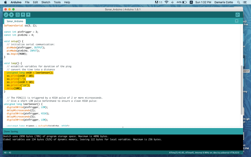
To establish the variables for duration of the ping, and to visualize or print in the serial monitor a distance, not time, I had to convert the time into distance.
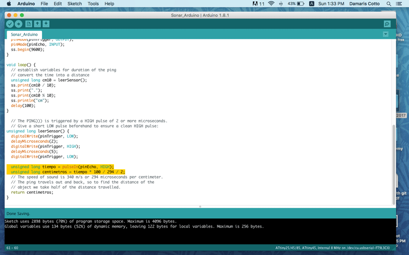
To convert time into centimeters, I learned in the ping example that the speed of sound is 340 m/s or 294 microseconds for centimeter, and the sound travels out and back, that's why it is divided by 2, if not, the distance is going to be the double.
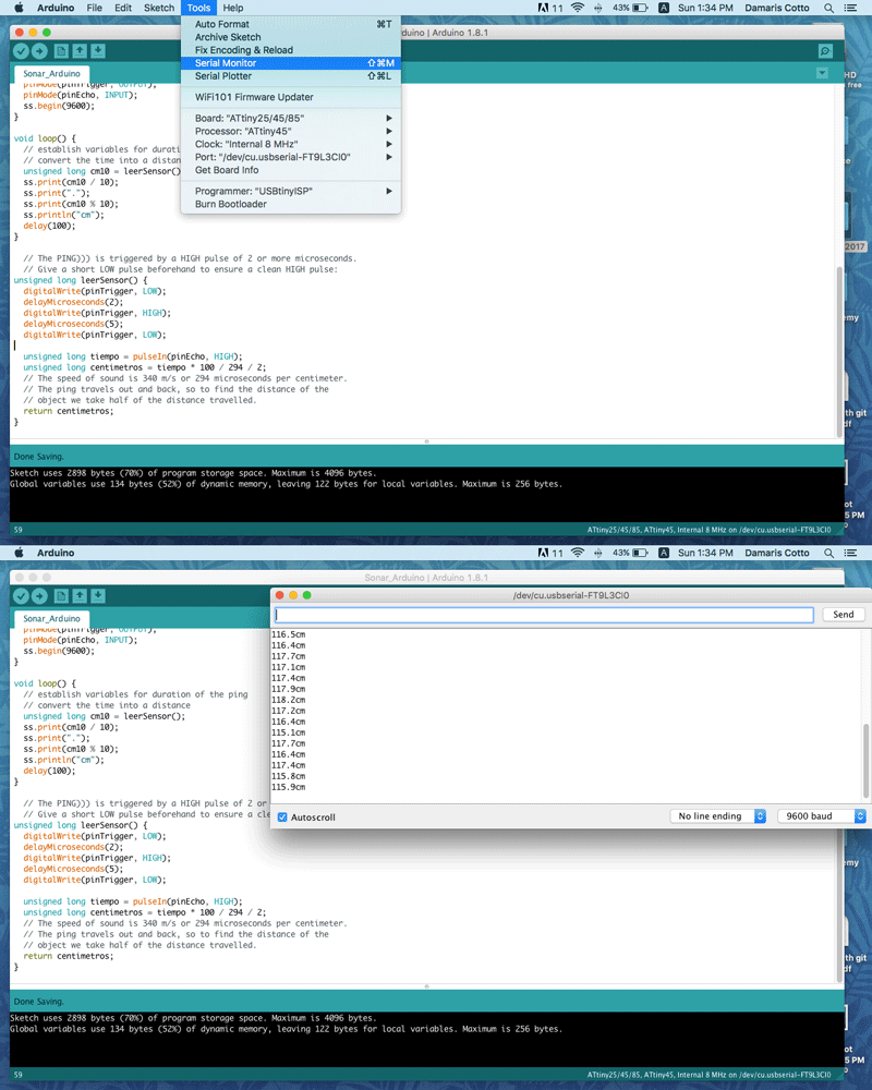
At the end, I upload the program to the sonar board using my Fab ISP board and once is compliled, I opened the serial monitor window to see the sonar measuring every 100 milliseconds.
This is a short video showing how it works.