CNC stands for Computer Numeric Control it is a process used in the manufacturing sector that involves the use of computers to control machine tools. Tools that can be controlled in this manner include lathes, mills, routers and grinders.
The process involves creating a CAD(Computer Aided Design) file of the desired object. Then a specialized CAM (computer aided Manufacturing) software is required to convert the 3D CAD file into a set of codes which the machines can understand. CNC machining language, called G-code essentially controls all features like feed rate, coordination, location and speeds. With CNC machining, the computer can control exact positioning and velocity.
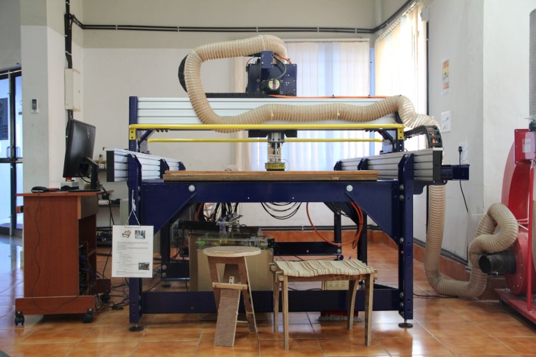
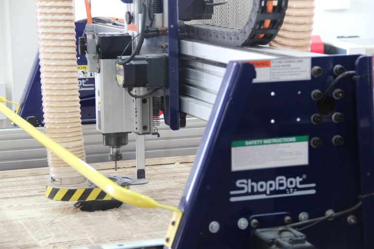
Shopbot is a large format CNC machine which can be used to cut timber, plywood, soft aluminum etc. It is a 3-axis machine and has a bed size of 4x8 feet. This machine is very modular. That means it can be easily disassembles and transported to a new location an reassembled. We have in our lab a.
The shopBot we are using is PRSalpha 96X48. Which has a Gantry size 96X48 i.e 8X4 foot.
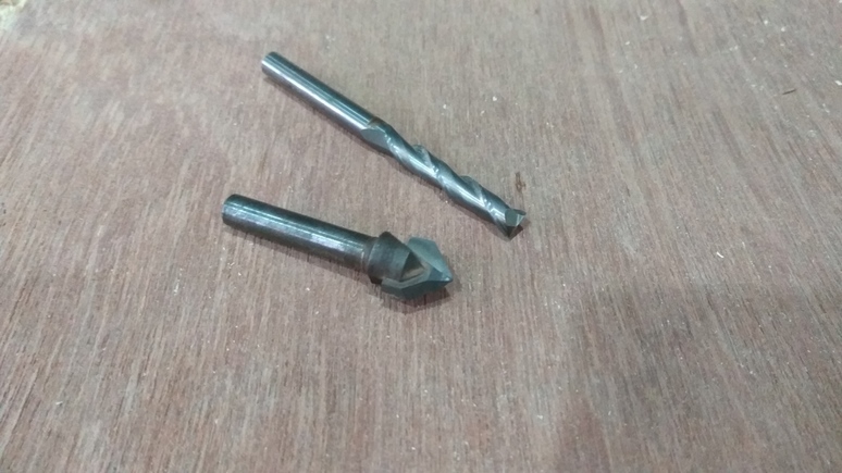
Drill bit Vs End mills
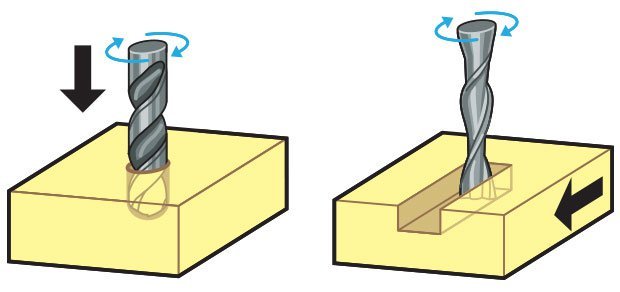
Though they might look same both of them are designed for different purposes. A drill bit need to cut straight into the material hence will have teeth at tip. But an End mill needs to cut from the sides also, that means it needs to have a cutting edge spiraling all the way up to the flute.
Flutes :- Flutes are the spiraling shafts cut along the surface of an end mill. They serve two purposes, one for cutting the material and other for clearing the wood chips from the cutting area. Less number of flutes means chips will be cleared easily but the cut will be of rough finish. Higher the number of flutes the smoother the surface, but the chips will not be cleared easily.
Upcut & Downcut
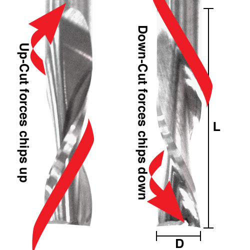
In an Upcut type end mill the teeth on the flute will point upwards. This means that the end mill is cutting and drawing out the wood through the flute. This is good for cutting deep into the stock. But this leaves a bad surface finish on the top of the surface.
A downcut type end mill has teeths that point downward on the flute. This means that the end mill will cut and try to push the material into the stock. This will give good surface finish on the top, but it is not very efficient at removing material.
Flat/ball end
flat end leaves flat surface profile on the stock and are good for removing large volume of material, but steps are formed when used for making curved surfaces. Ball end leaves curved surfaces and forms smooth curved finish while cutting cavities. They are used for finishing cuts.
Chip load :- This is the amount of material that is removed in each chip. The value is approximately = feed rate (inches per minute) / (RPM x number of flutes)
Cut depth :- This is the measure of how deep the end mill should go in each step while milling. Ideally cut depths should be less than 1/3rd of the length of the tool. They are mentioned in the product manual of the tool bits.
Step over
In a pocket cut the machine will traverse the entire area of the cut. It does that with a series of paths that cover the entire length and width of the cut. While doing this the step over determines how much the adjacent paths overlap each other. Usually we use it at 50%, ie the adjacent end mill cuts will overlap 50%, which gives a better finish.
The ShopBot is like any other CNC machine which we have used previously. It runs on a series of commands which are called G-codes. These codes are like instructions executed line by line, they tell the machine where to move and what to cut. There is a whole host of processes involved in computer controlled cutting, and it all starts with a CAD design.
This is usually the first step in any CNC manufacturing process. You have to first design what you are going to cut. For cutting you need a 2D vector path of the part. You can design in your favorite design tool and export as a .DXF file which can be used by Vcarve. I used Solidworks for designing the path and Rhino for some light modifications as it is easier to edit DXF files in Rhino. Once the CAD design is done now we can move on to the CAM setup.
For controlling shopbot, we need to generate a G-code file from the CAD, in order to do that we need a CAM software. We use Vcarve for generating the shopbot file from the CAD design.
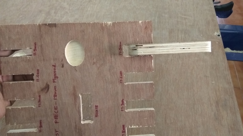
We did a group task of finding the tolerance required for press-fit assembly. We have in our lab plywood sheets of 18mm and 12mm, hence we cut slots from 18 to 17.5 in steps of 0.5mm and the same with 12mm.
We found out that the right fits comes somewhere near 17.5 and 17.6mm. The material thickness does vary a bit hence I decided I would put a value in between these numbers.
ShopBot is unlike any other machine we used before, we cannot just click print, like we did with the laser cutter. There is a lot that needs to be taken care of before you can cut.
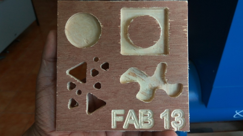
So to learn how to use the software and setup the machine I decided to cut something small. It would be 15x15cm with a pocket, a projection, a few slots and some text. I was aiming to use maximum variety of tools and learn how they work.
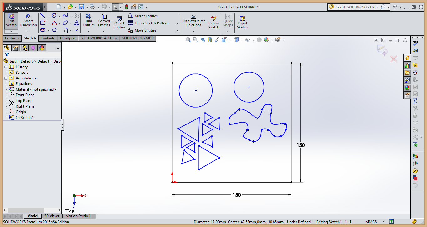
I designed it in solidworks and exported as .DXF and imported it to Vcarve. In the first step it will ask you about the material, the thickness, the offset if necessary, and where you want the origin to be etc. Set them appropriately.
I gave a 6mm pocket on the two circles, one inside and on the other I drew a square and pocket cut the area between them. Same with the curve also. I put small triangles in the design as I wanted to see how they would come out, I was thinking of including a triangle pattern in my design. We can’t cut directly from Vcarve, so I exported the tool paths as a ShopBot file .sbp I set up the machine properly and put in the correct bit and set the origin points on 3 axis and started cutting. It came out as I hoped and I learned a lot about how the software sets up the tool paths and how to set up the machine properly.
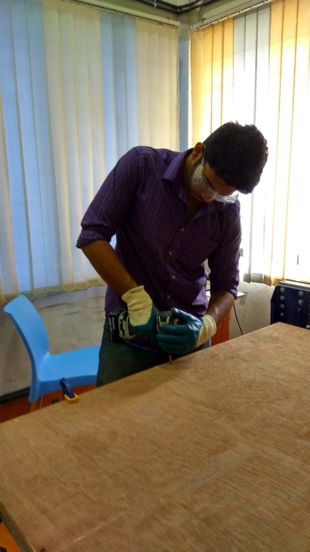
When working with a CNC tool always remember that you are not the one controlling the machine, you cannot predict where the spindle will go. As is you should never reach your hand into the machine when it is working. Never work with ShopBot when you are distracted or sleepy. Some Cuts can take hours and you should not leave the machine to run on its own.
Its important to wear eye protection and gloves at all times. The machine spindle is rotating at 12000RPM, it can and will spit out high speed projectiles at you, and If you are not careful it can seriously harm your health.
Once you have set all the tool paths in the software we can begin setting up the machine. First you have to load the stock into the machine, align it properly to the bed and fix it in place with screws.
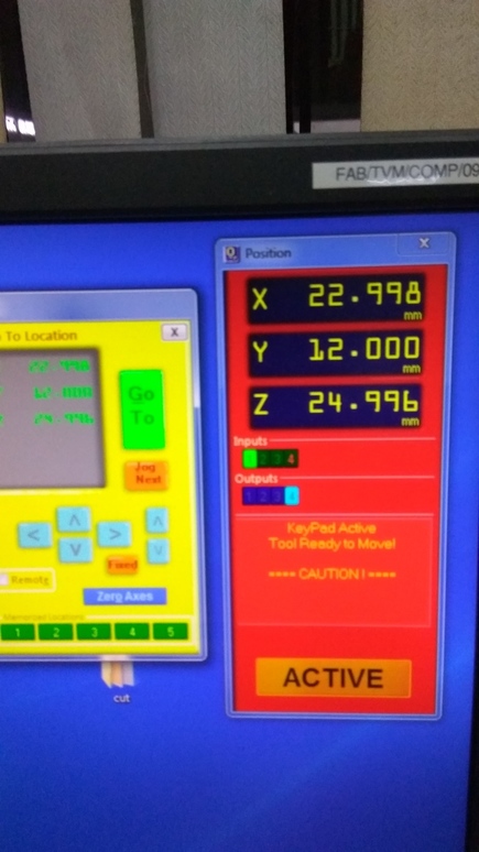
Turn on the machine from the control panel on the right side. Now the first step would be to bring the spindle to the home position. To do this, open the shopbot 3 application in your computer, you can see a red control panel indicating the current position of your spindle.
There is a button with XY written on it this is the return to home button. The machine has a home position at the top right, near the control panel. Once you click it, an alarm will go off indicating that the machine will now move.
This would be a good time to put the bit into the machine, you can move the spindle using the arrows keys on the control panel.
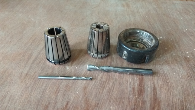
Once done, get the wrenches out and remove the collect chuck. Put in our new bit and tighten it properly. Remember to never put the bit in too deep or too shallow. The chuck should close just above where the flute ends.
Once the machine is in the home position move it to the place where you want to cut. Note down this position in case something happens and you have to stop the machine or if power goes out. Now set the origin.
For setting the Z-axis we have a plate which is electrically connected to the machine. The way it works is that you place the plate, on the surface, below the bit.
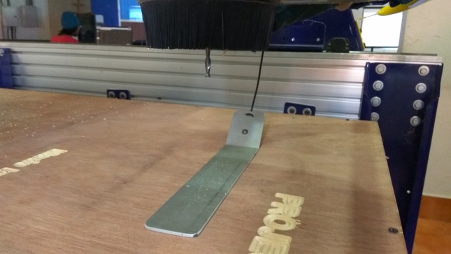
The machine will move the z-axis down. When the bit touches the plate, a circuit is completed and the machine will set the origin. Now you can begin cutting.
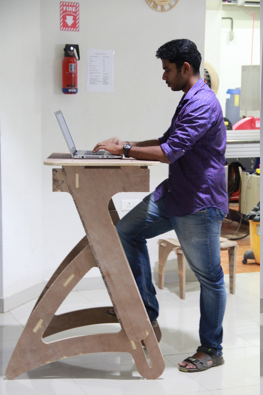
I wanted to make a standing desk for quite sometime as most of the time when I’m sitting down to work on my computer, I will have back pain. I know this is not a healthy habit hence, in the past I have used some small stools, kept on top of my table which allows me to work standing up, but its very difficult to adjust the height of them. Hence I wanted to option for adjusting the height of the desk so that it will suit the height of the person using it.
I started researching online for inspiration and found one on kickstarter. These guys have designed a table which is very easily adjustable. I loved the design of it, though I have tried in vain to understand how their design actually works. I set about to design one with how I think it works.
The main thing that I liked about this design is the ease of adjusting the height without requiring any complicated fixtures and holders.
I started designing the table by estimating all the dimensions. I measured approximated dimensions using tape and started drawing out my design. I went through several iterations of drawing before I got close one which I liked.
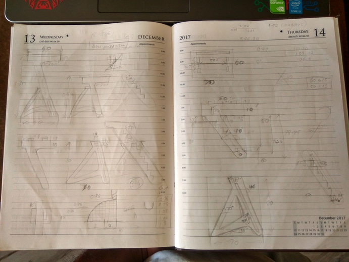
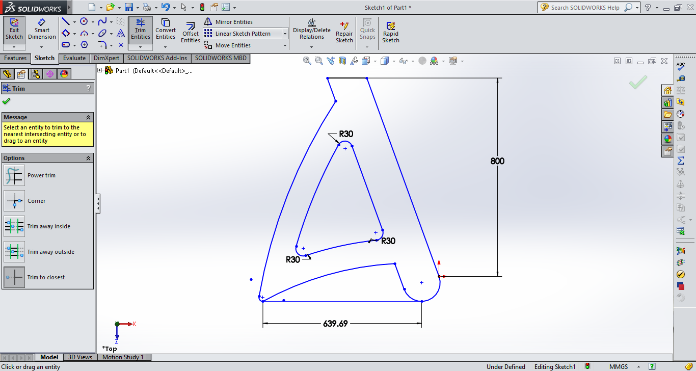
With the approximated dimensions, I started drawing it in Solidworks. While sketching itself I could understand some of the obvious dimensioning errors I made and I started correcting and redrawing it again and again. This took a lot of time.
I started by figuring out the angles the legs would be tilted from the vertical. I approximated 70deg to be the angles, any more means it would put too much torsional force on the material and any less it would limit the height range of the table.
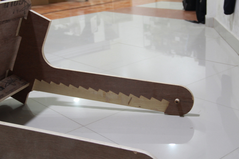
I’m planning on using a saw-tooth cut profile to act as the height adjusting mechanism, this will rest on a key which will act as the load bearing member. The table will be two section, top and bottom. The top will be connected to the bottom at only two points. One on the key which the saw-tooth is resting on and another on the slot which I’ve cut on the bottom piece.
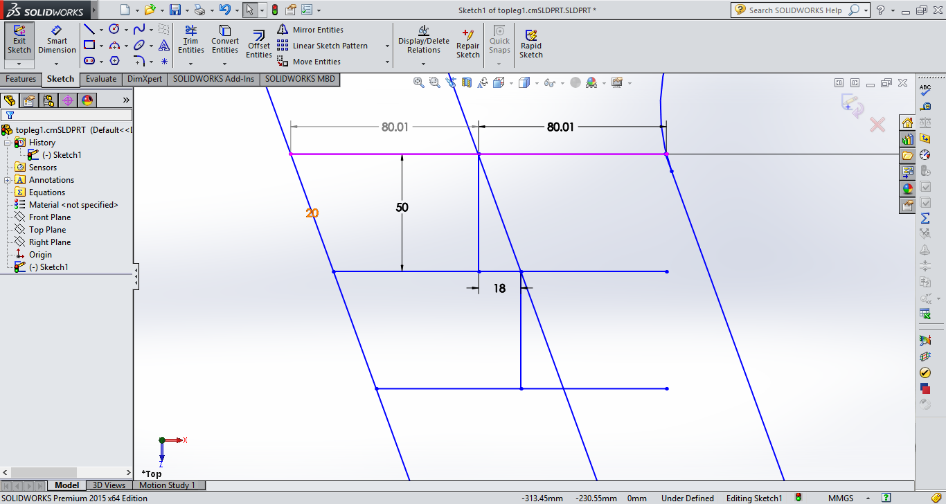
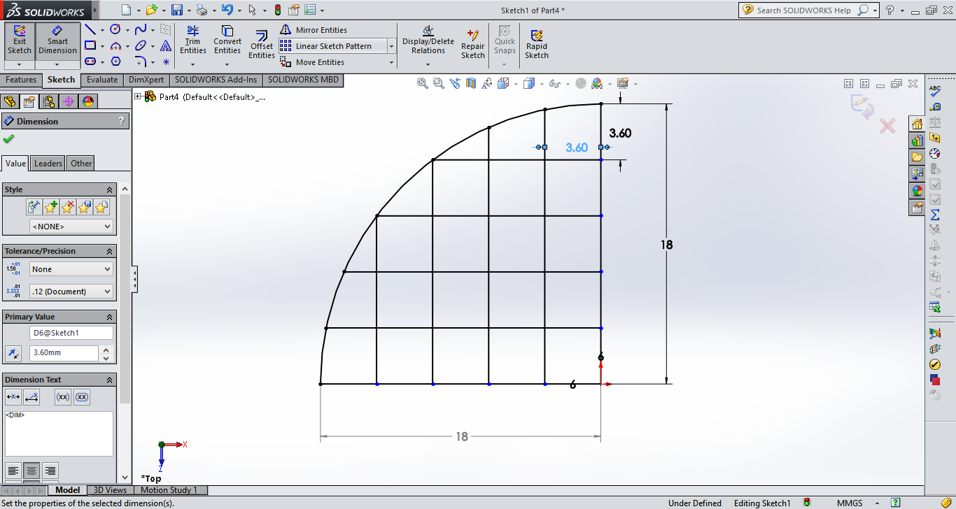
For drawing the sawtooth profile I drew a reference line on the middle of the leg and and drew lines at constant intervals, these would be my steps.
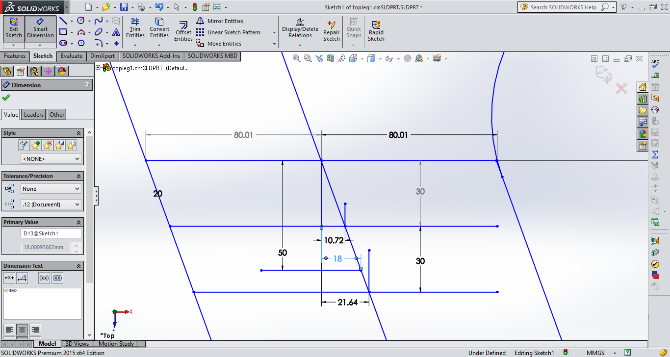
I had initially planned on making steps at every 2cm, but while designing I understood that was a mistake, the step width would be very small. Hence I increased the step height and found 5cm steps to be ideal
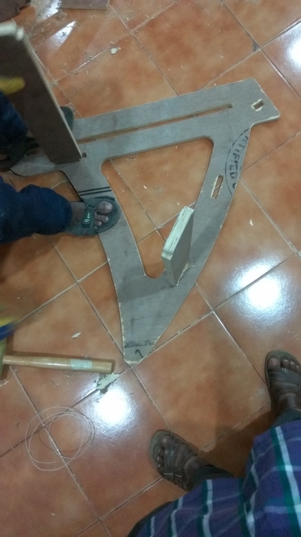
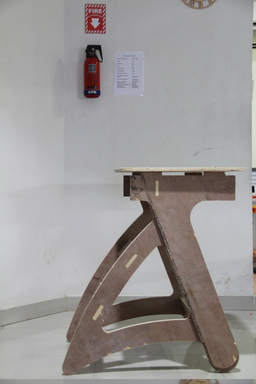
The saw-tooth will not be visible from the sides and will be on the internal part of the top portion. Hence my option is to pocket cut and remove all the material from the teeth till the edge.
The top of the table has to be level at all the heights the table is designed for, hence I need to design the angles properly. The step of each teeth has to be fully resting on the key otherwise it cannot support the load.
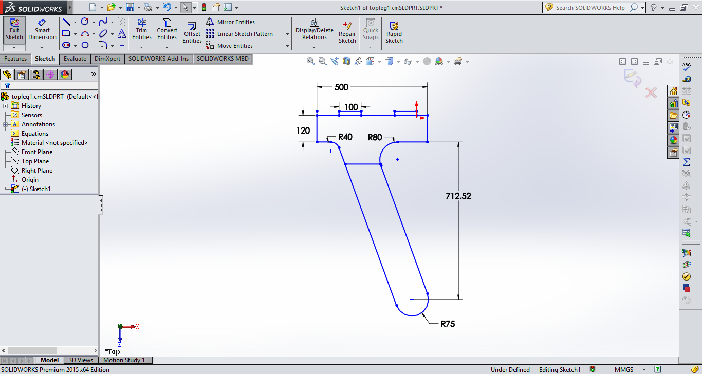
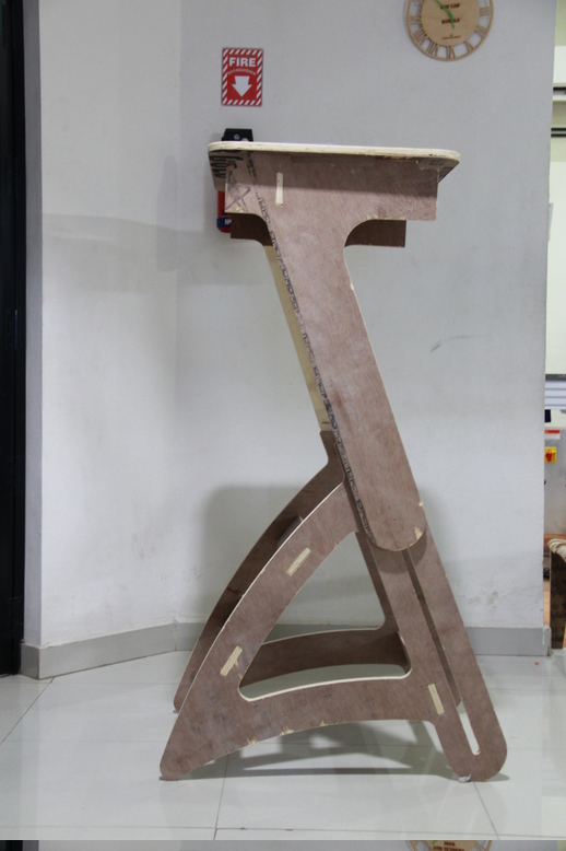
Now in drawing the bottom leg I have to keep the same 70deg angle and design a base for it. The challenge for me was I wanted to make the base legs curved. This poses a problem that when you join two curves together it touches in a point.
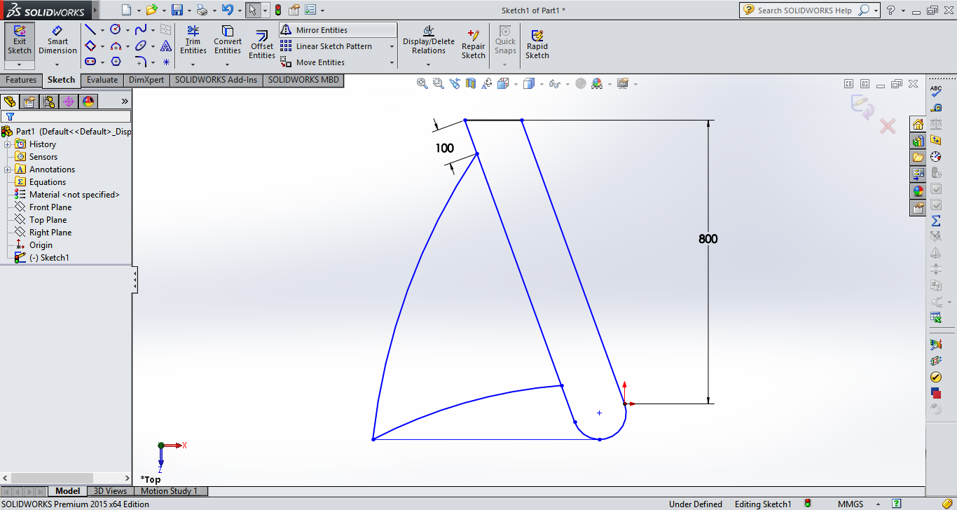
I want that point to be filleted, but if you give the option to fillet, the meeting point will now be raised from the ground, which means you have just changed the angle slot. I solved it by drawing a reference line, which will act as my ground line. Then I used a tangent curve to draw a curve meeting the two points while keeping the bottom point on the line, this way the structure would remain horizontal.
Now to connect the to sides of the table I would need rectangular connectors which will press fit into both sides. I have 3 slots on the bottom part of the table and one slot on the top part.
I made the ingenious mistake of designing one connector to fit all the holes. Whats seems to be the problem right? Well it was not apparent to me till I cut all the pieces, filed it all down, chamfered the edges and tried to fit it.
The 3 connector on the bottom went in smoothly, I had given very fine tolerances on both sides of each slot, so that I would get a good interference fit. They were difficult to push through but after some manual labor they all went in nicely.
The fit was good and the structure was solid. It can take a lot of load and does not bend easily. I can even stand on the connectors.
Only when I fit the last connector to the top section and tried to put the top section on the bottom, did I realize my mistake. The top and bottom sections where separated by the same distance, I wanted the bottom to be inside the top section. The simple law of physics that two object shall not occupy the same space at the same time was preventing me from fitting the top to the bottom. Well, that is when things went downhill. I should have done a small laser cut version first. Lesson learned. Next time I'm making something big, I'll first make something small.
I was drawing everything in 2D while visualizing how it would fit in 3D, since I was going through iterations of drawing and redrawing, I did not convert my sketches into 3D, big mistake. I should have taken the time to convert them to 3D and assembles to check the fits.
I had cut out all the pieces, including the top plate, which had four slots separated by the same distance as the middle connector.
I cut out a new connector for the top section from the scrap I had from my last cut and proceeded with the build.
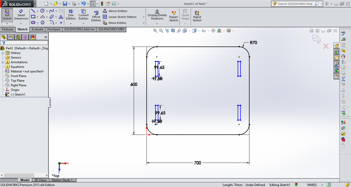
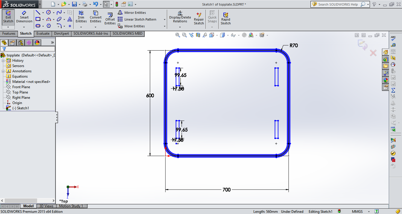
The top plate would be joined to the top leg at four places, I estimated the size of the top plate by giving enough space to put both my laptop and my notebook at the same time. This came to about 70x60cm.
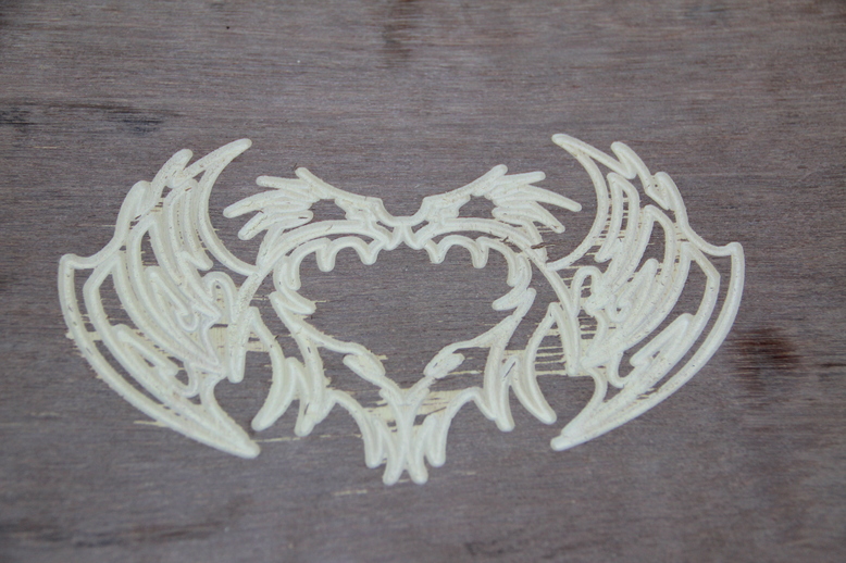
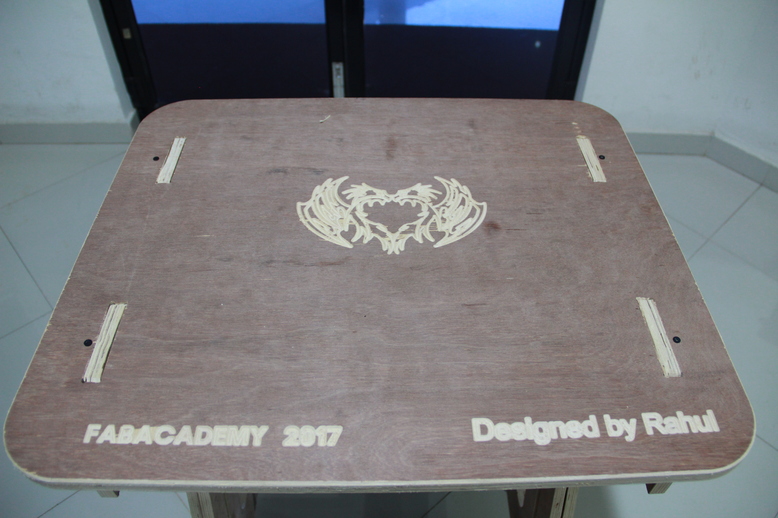
I also wanted to engrave my name and a cool design on my top plate, since it had a lot of free space. I went with a simple design of two dragons and some text. The dragon was converted from an image by tracing a bitmap of it using edge detection and exporting as DXF. I engraved the design with a V-bit and depth of 1.5mm which was a bit more than I imagined.
Considering ergonomics I wanted the outer edge of my top plate to be filleted, since I did not yet know how to carve in 3D using the Shopbot. I cooked up an ingenious solution to cut in 3D using 2D sketches.
My plan was to draw multiple paths offset-ed both inside and outside my original cut line. And I would vary the depth of each pass. We have a 6.35mm ball nose bit. Hence I decided to divide my cut into 5 different cuts of varying depth. I had hoped that the ball nose would create a profile tangent to the tool.
When I went to my instructor with this plan he said it might be risky as ball nose are usually used for finishing cuts and cannot remove a lot of material. Hence I abandoned it for a simpler one.
My new plan is to use the engraving V-bit itself to create a chamfer on the cut line of the top plate. I gave a depth of 2mm and cut it out. It works fine and is a quick and easy solution.
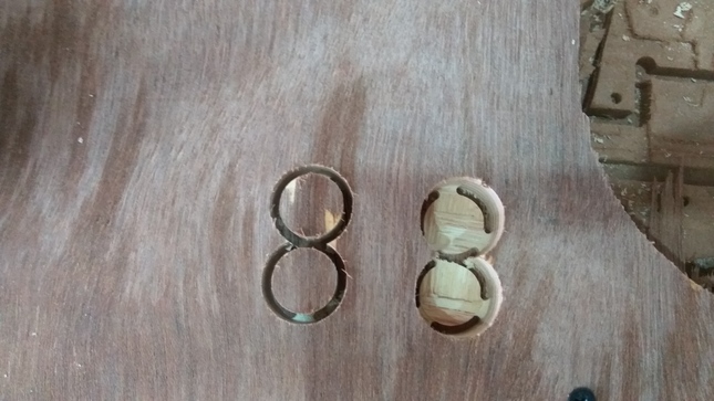
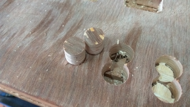
The top half is resting on the bottom at only four points, two on the key which supports all the load and the other two, small 2cm diameter cylinders which slide inside the slot of the bottom legs.
I cut the cylinders using a 1/8 inch (3mm) up-cut milling bit. My instructors told me that if the cylinder break off and hit the bit it might break, hence I had given 3 tabs on each cylinder to ensure that it would not move. I found out its very difficult to remove the tabs without peeling off the bottom layers. Hence I cut again, but this time I put only one tab. This was fairly easier to remove.
I designed the top leg to rest on the bottom at two places, one in the key and another in the slot. The connection in the slot is meant to be sliding. I had assumed that the the joints would be perpendicular and that I would not have to lock it from the other side.
Hence I designed a simple circular peg which would rest in the slot. I thought about designing a T-shaped peg that would lock it from the other side but I wanted the table to be easily disassembled, thats why I went with the simple peg.
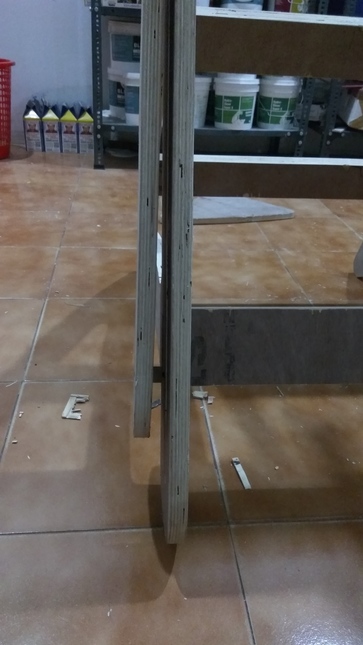
As with all designing, you have to entertain the possibility that your assumptions might be wrong. I found this out when I assembled the piece. The plywood I cut on had a slight bend, this meant that the joint was no longer straight.
Learned a valuable lesson then, Never let your design depend so much on the dimensional properties of the wood.
Designing the table was a lot more complicated than I imagined, The design looks deceptively simple, yet it took me more than two days to get all the dimensions and fits within reasonable estimates.
The cutting section was smooth, I faced little problems. I opened the DXF file in Vcarve and started giving all the tool paths. I made sure all the open vectors were closed. There are a lot of setting you have go through, like choosing the correct bit, setting the cutting depth, the pass distance etc.
The general order for giving tool paths is as follows
Select the path you want to cut (make sure they are closed vectors)
Choose the appropriate option (Profile cut, pocket, Drill etc)
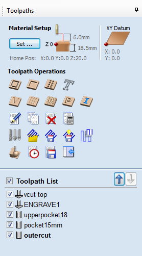
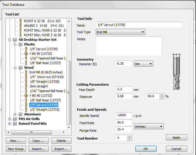
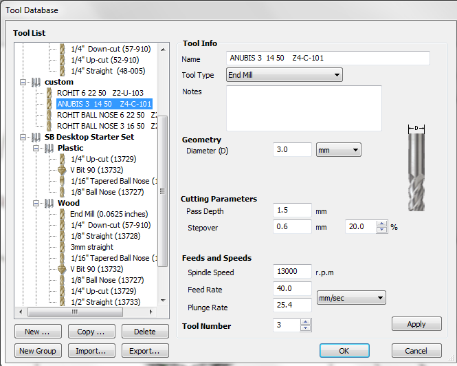
Set the tool you will use from the library. (you can see the settings for the tool in the window, and edit them if needed.)
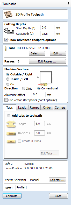
For profile cut select inside, outside, or on the line.
Add tabs if necessary.
Click calculate
save tool path to file.
When cutting remember all the safety precautions, wear eye protection gloves and shoes when cutting. Cutting makes a lot of noise so keep yourself protected by wearing ear protection. Remember to turn on the dust collector so that all the debris will be sucked out of the cutting area.
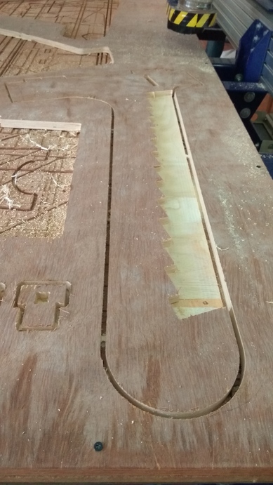
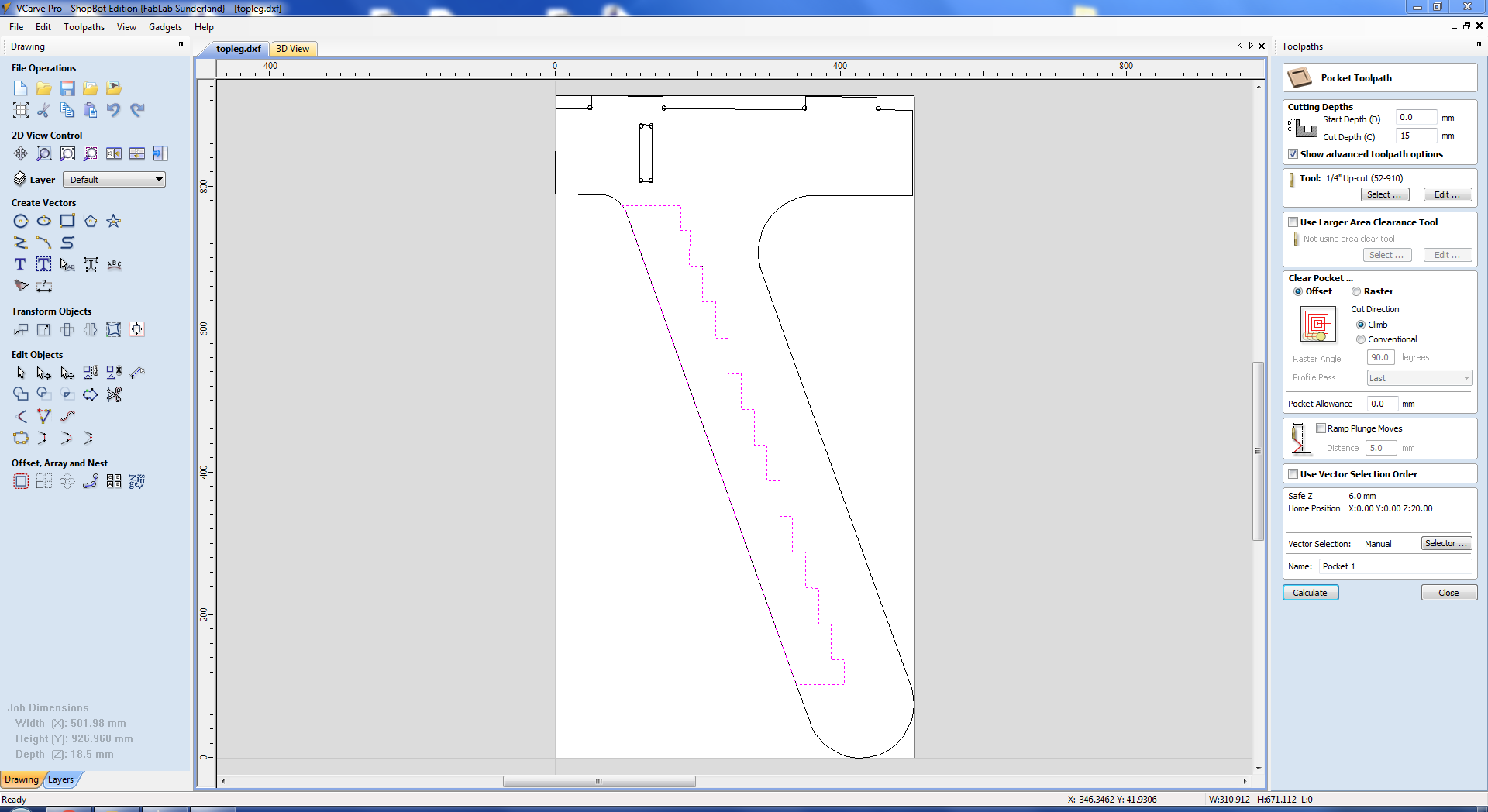
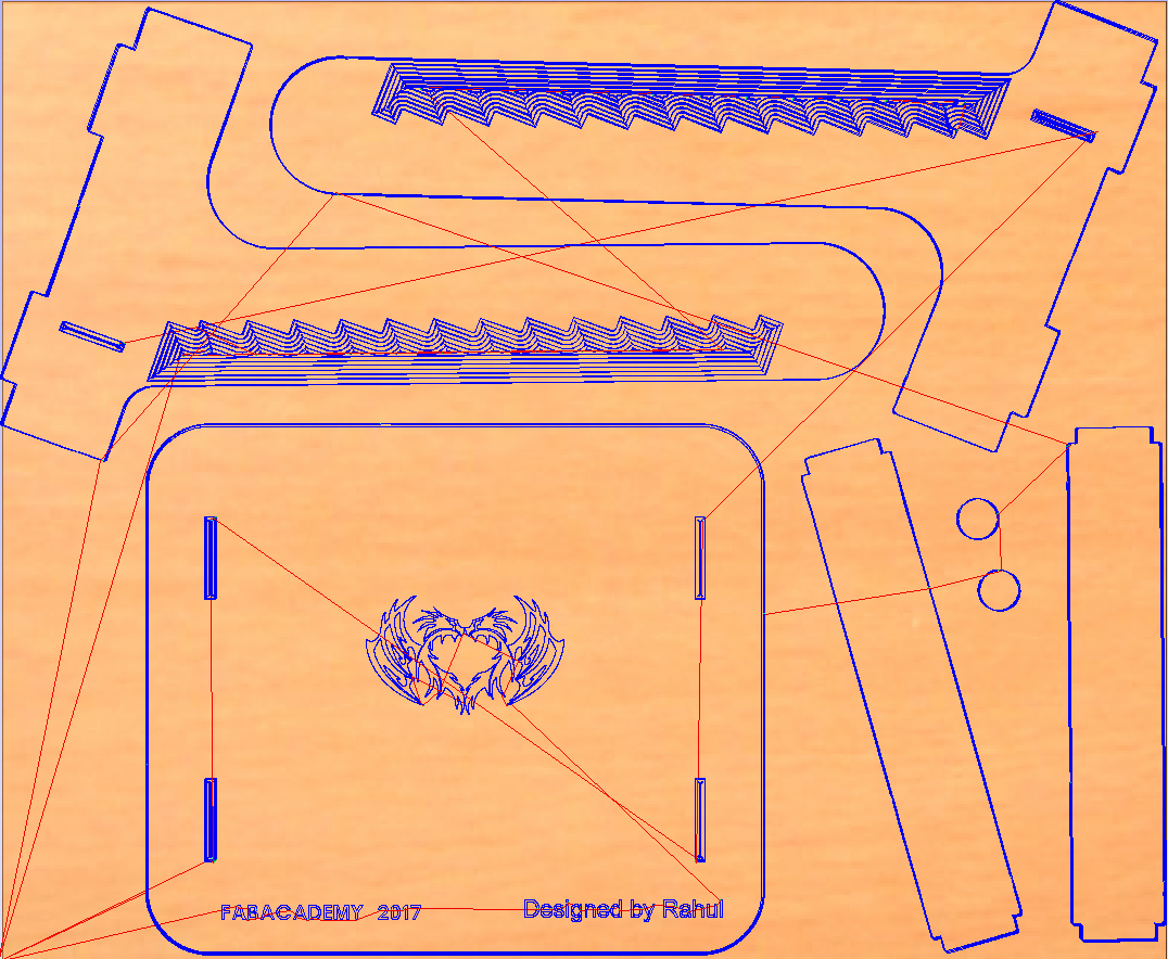
In my design, I wanted to hide the sawtooth from the outside, hence I gave it as a pocket cut with a depth of 15mm. This meant that I had a lot of wood to remove. In my first cut I selected the entire path in Vcarve and gave it as a pocket cut.
When the machine started cutting I realized one glaring problem with the way the software gave the tool paths. The setting I gave for cutting was the offset option, in which the tool will cut from the inner edge to the outer edge by tracing the perimeter in steps.
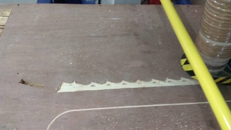
I realized how the software gives tool paths from the design, so now in my next pocket cut I split the geometry into two. I drew a line close to the teeth to separate the paths, now I have a small section where I have to cut the teeth and a large rectangle area where I need to remove the material.
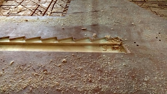
This was a lot quicker. The larger area is now a simple rectangular geometry hence all the machine has to do is trace out straight line, which are much faster than the teeth profile.Hence the cut time was reduced considerably.
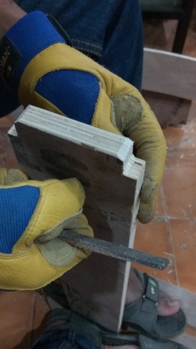
The assembly section was lot of manual labor, I had given tight tolerances for all my fits and forgot to chamfer all the edges, so I manually cut chamfer on all the connectors using the band saw. This was good a exercise, now I learned how to cut properly using the band saw, which turned out to be very useful in the end.
The pieces after cutting will have rough finish on the edges, hence I filed it down using a flat file. When assembling align the pieces properly and then only hit with a mallet.
If your design has small parts which need to be press fit, be sure to take your time and hit it in gradually. I broke one of my keys partially when It got stuck and I used a bit more force. The problem is the plywood is made up of layers which are stuck together. Some layers might not be strong hence when you hit, they might come apart.
I used screws to join the small cylinders on to the sides of the top legs. I was going to design an elaborate T-section which will slot into the place instead of the pegs,but because of lack of time, I went with a simple screw joint.
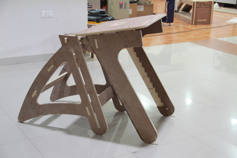
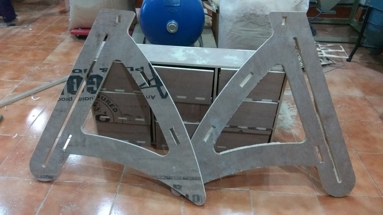
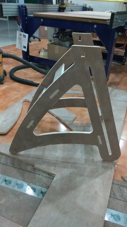
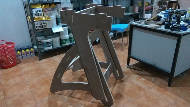
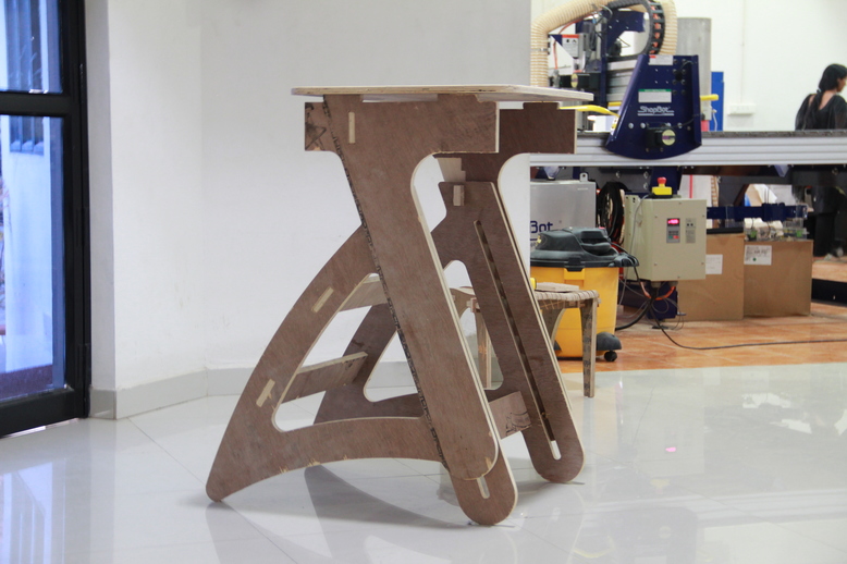
These are the two parts which make up the full structure. The two structures are connected at four points, one on the key, which is the load bearing member and the two pegs which slide into the slots on the bottom part of the leg, preventing the top leg from overturning and effectively constraining the structure.
In the initial phase I was focused on figuring out the dimension of the table, I was measuring with tape to get an approximate idea about how big the table should be. When I think I'm close to the dimensions I need, I create a sketch from the values I have written down. After drawing one part I would come back and change the sketch of the previous one, this is a really iterative process. Hence I choose to leave the sketches in 2D. If you choose to do this then you should definitely test your design before cutting.
I made the common mistake of thinking that my design skills are good and that I have thought of all the possible outcomes, well no matter your level of expertise with design, its always better to make a scaled doen version of the thing you want to make. I learned this the hard way, when I designed a connector for joining the two sides of my table, I made the mistake of making all the connectors the same length. The top portion is wider than the bottom, and I had to redesign and cut out that piece.
I have probably made almost all the mistakes that can be done in this week. The plus side of this is that, I have learned, what to do and what not to. These experiences have become invaluable to me and I'm better prepared to handle them in the future. I have big plans for my next builds, Now onwards I'll pay special attention as not to make the same mistakes again.
rahulsrajan.com
rahulsrajan01@gmail.com
Trivandrum, Kerala ,
India.

Technopark, Kerala, India