Kinect is a line motion sensing input device developed by Microsoft for the Xbox 360. It uses a system consisting of an infrared projector and camera and a special microchip that generates a grid from which the location of a nearby object in 3 dimensions can be ascertained. The device features an RGB camera, depth sensor and multi-array microphone running proprietary software, which provide full-body 3D motion capture, facial recognition and voice recognition capabilities.
Kinect requires the appropriate drivers to be installed on the system. You can down load them from the Microsoft website. Choose the driver appropriate for your system and install them. Additionally you also need a 3D scanning software for scanning.
Kinect needs be externally powered and I have experienced sensor unavailability issue a few times. But in the end it is what worked best for me in scanning compared to Real sense. Some of the things I liked about the kinect is that it has good range compared to Real sense, which is very short range. It gives good depth resolution and is pretty fast. But it has a large minimum resolution distance less than which it will be unable to scan the objects very near to it.
I first installed the drivers for Kinect and supporting software and I was able to scan with decent resolution. I’ll share my experience with different softwares I used. My main problem was that we did not have a proper base for holding the kinect and in our first scans we tried placing it on top of something and it was not stable. So me and my friend Syed we decided to design and 3D print a tripod holder for kinect.
We started drawing various designs for 3D printing. But the most challenging part was measuring the dimensions of kinect. We have a vernier caliper for measuring the dimensions but it is very difficult to measure dimensions when there are curves. Hence we decided to download a cad file for the kinect and print it. We found some designs which are similar to ours and printed it.
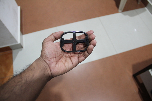
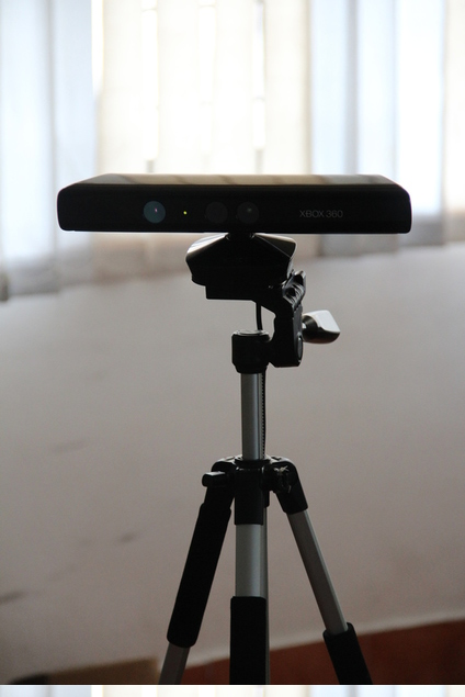
Now we are scanning by placing the kinect on a tripod using the holder. Now we are able to scan properly.
Skanet was an easy install and the software worked properly, it has a smooth learning curve and gives decent scan. The scanning procedure is layed out in steps and is easy to follow. In the first step you have to set your bounding box and the nature (size and orientation) of the item which will be scanned. In the next step place the object in front of the sensor and click record.
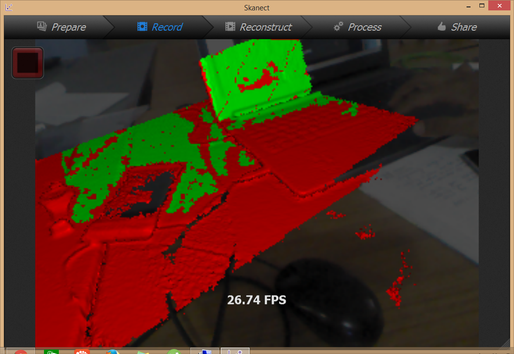
It will start capturing the 3D data and now either rotate the object of the sensor 360 degrees. The scanned portions will be in green and the rest will be in red. Be careful of moving the sensor too fast as it will lose tracking and you will have to go back to the last position where you lost the tracking.
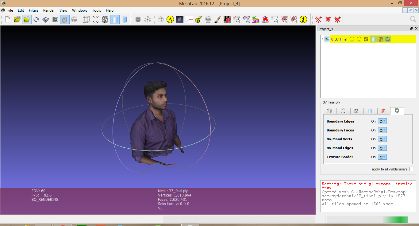
Now in the Reconstruct tab, the software will create the mesh based on the captured data. You can now see the full 3D mesh. In the process tab you can process the data fro printing, It will create a manifold design and fill holes in the model.
Reconstructme is another free software, that I tried, it’s a bit difficult than skanet and the user interface is not friendly. There is less graphical cues to guide the user and there is no live preview. You have to first input your settings and click scan and the object will be scanned with the settings. The main difficultly I had with reconstructme was that it lost tracking quite often which makes It unsuitable for hand held scanning.
The feature I really like in reconstructme was that option for selfiescan. In which a person sat infront of the sensor and turned around a full 360 and the software would map the 3D profile. This worked well enough and the 3D model it generated is acceptable. There was a slight problem of misalignment in the textured model, where the colour reproduction was a bit off. But for a free software it is good enough.
This free software is a simple, yet powerful piece software. The user interface is better than reconstructme and it is easy to learn this software. This is a bit more manual than Skanet but it is good enough to work with.
The way it works is that you have to first keep the object in front of the sensor and click scan. Then the software captures a snapshot of the object and the 3D data. Now you have to rotate the object a certain degree and then click scan again and then a new snapshot will be taken. The software then attempts to align these two meshes to create a part of the object.
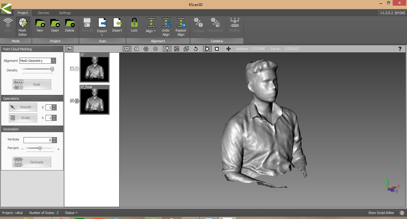
One drawback of this method id that, the top of the head will not be scanned properly, I'm experimenting with different angles and orientations to see what works.
The main problem with this is that the aligns are not always perfect, and some meshes will not align itself. You can solve this by either deleting the problem mesh and scan again with a bit more overlap or you can edit the mesh and orient it on the same plane and click align again and the software will align it for you.
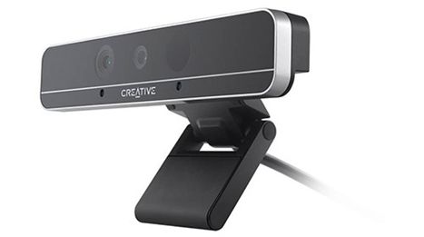
Intel realsense is a depth perception camera, that is developed for communicating with the computer via gestures, the hardware components of the kinect and realsense are similar. They both have an RGB camera, an infrared laser projector, an infrared camera and an arrays of microphones.
Realsense also need their proprietary drivers, download and install them from the Intel website. In my experience, Real sense was difficult to work with. it did not work on some laptops and the device did not load properly, even after repeated installations. Downloading drivers from the Intel website is not straight forward, you have to create an account and register your product before you can begin downloading drivers.
In the end it worked on one Desktop in our lab and we used it to test run the product. We tried to scan a person’s head and create a 3D model but what we found was that the range of the device is very small. You have to sit very close to the sensor to be able to get a good scan. We used Intel’s software itself to scan the head. The result was not that great, the 3D model generated was not accurate and even slight movement in your head will result in a ruined scan. Real sense was designed for gesture controlling your computer, It is not suitable for 3D scanning.
The main limitation in 3D scanning is the hardware you are using, if you have a portable high end scanner, you can get detailed resolution scans, but if you don't then it really limits your options in the things you can scan.
For example, in our lab we have the kinect sensor and the Intel Real sense. From my experience using them, I can say that the kinect is not suitable for small fine details, it is good for large long range objects like furniture and rooms. It has very poor resolution.
I have limited experience with Intel Real Sense, since was not able to get it working in my PC, but from my limited experience I can say that it is not suitable for long range scanning.
3D printing is also known as additive manufacturing where successive layers of a material are deposited on top of one another in a computer controlled manner to create a 3D model.
Stereolithography (SLA), Digital Light Processing(DLP), Fused deposition modeling (FDM), Selective Laser Sintering (SLS), Electronic Beam Melting (EBM)
In our lab we use the Fused deposition modelling type printers where, a small plastic filament is melted and extruded through a small nozzle to form the 3D shape of the model.
We have two 3D printers in our lab
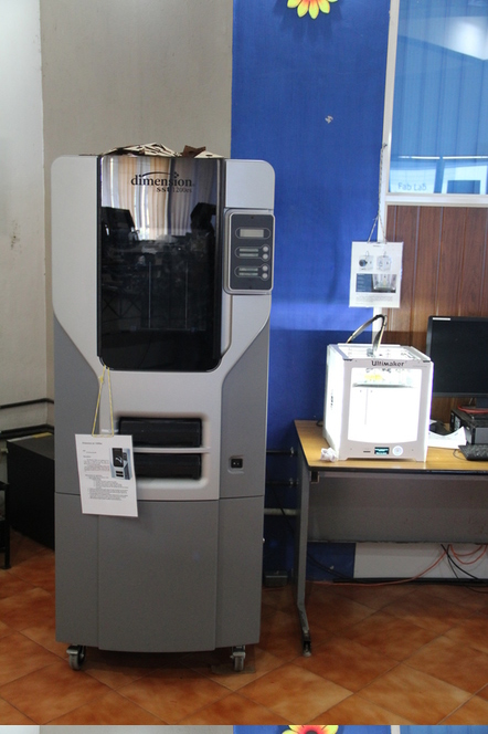
1. Dimension
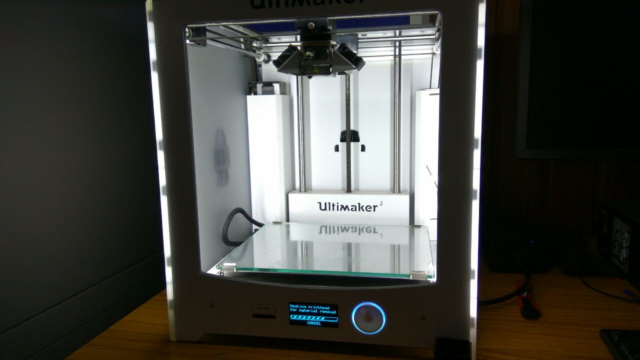
2. Ultimaker 2
Your design must be Manifold (watertight). 3D printing requires volume, hence you cannot print surfaces directly.
Add wall thickness for hollow designs
Avoid Mesh errors, Close all the Holes in your 3D file.
Combine geometry so that the model has one continuous surface.
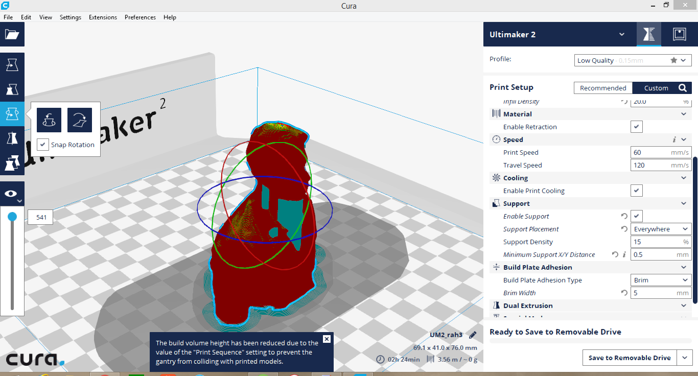
Cura is the software which we used to convert the 3D model into G code which the machine can understand. What cura does is that it slices the 3D model into a series of layers, which will be printed one at a time. We have many setting we can change like the layer height, fill density, support density and type etc.
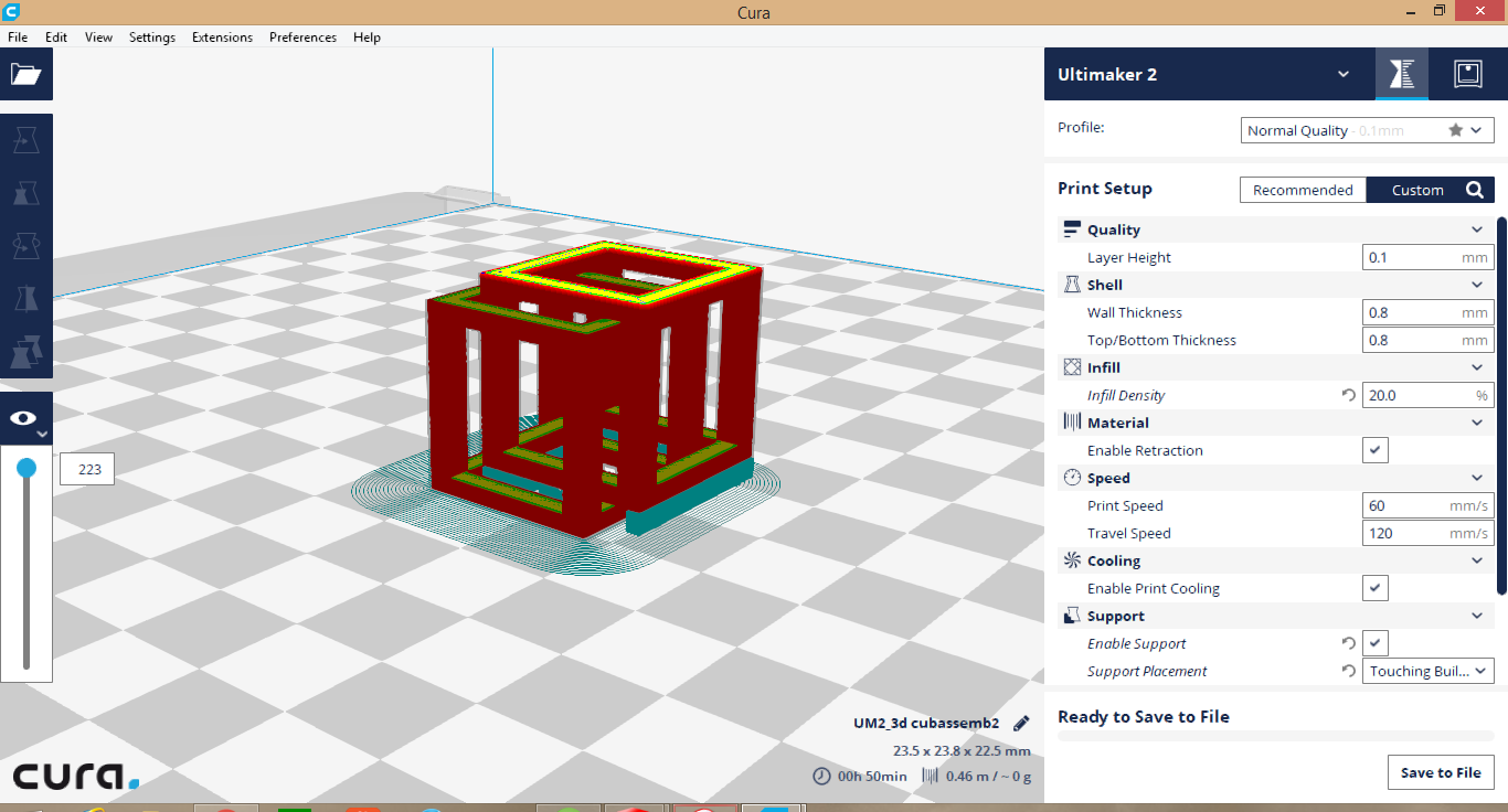
To 3D print in Cura, Open your .stl file in Cura, now you can see your model on your print bed. You can move it around and scale it up or rotate it. In the settings pannel, you can change thelayer height, the fill density, the support type and density.
Now click save to removable drive and insert the drive in the machine to start printing.
3D printers have very minimal setting up to do, the only work we have to do is changing the material.
Changing the material
On the main menu go to Change Material, The print head will heat up to enable retraction of the filament.
Once it heats up, a stepper will automatically pull the filament from the extruder and out of the tube.
Click ready to start inserting the material, it will go slow at once and once it clears the driving gear teeth, click ready again to pull it faster.
Wait until the material starts coming out of the extruder and now click ready again.
Material jamming
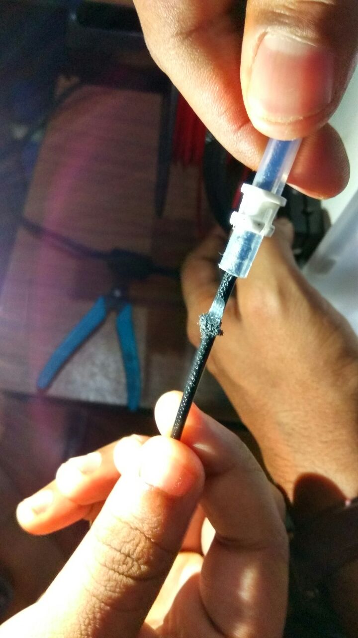
This happened to us quite a few times, while changing the filament material. This is a design flaw in the Ultimaker system. The extrusion head did not heat up properly to loosen the plastic and the drive teeth of the filament dug into the filament.
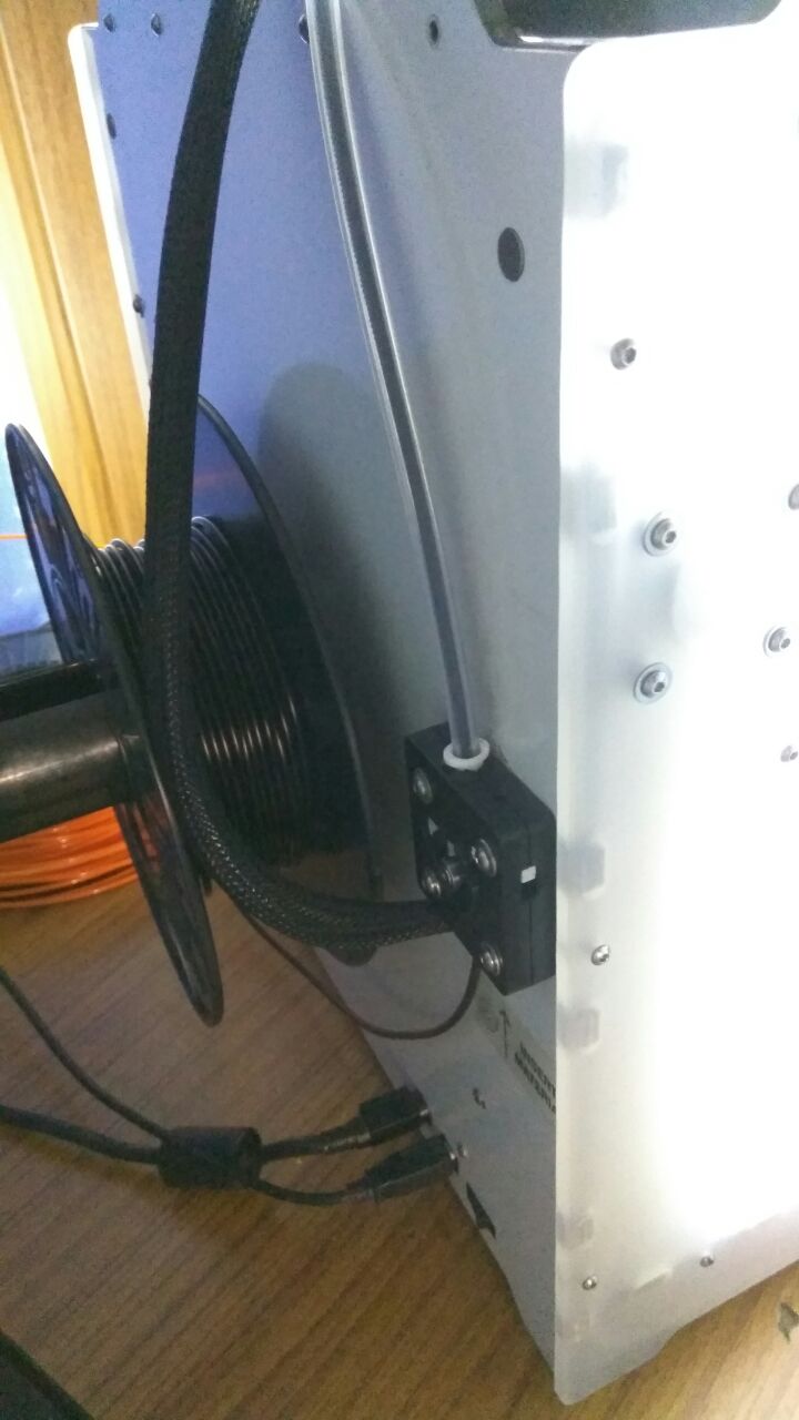
Now the only way to remove it is to open the tube, cut out the portion sticking out on the side of the extruder. Now try and reverse the material again, but this time give a slight pull to the other end of the filament after the drive gear. Hopefully it will now come out, if it doesn't then you have to open the drive gear assembly and loosen the spring and remove the material.
Understanding our 3D printer's limitation is important because this will reflect on the actual print quality of our prototype. One of the main parameters is the resolution, The resolution of a 3D printer is measured by its layer height. The lower the resolution the higher the quality of the print. We have downloaded a test print model from thingiverse and is shown below with the test parameters.
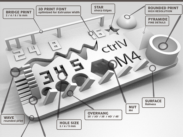
size: the object is 2x50x30mm (baseplate)
hole size: 3 holes (3/4/5mm)
Nut size: M4 Nut should fit perfectly
fine details: pyramide, cone, all numbers
rounded print: wave, half sphere
minimum distance & walls: 0.1/0.2/0.3/0.4/0.5/0.6/0.7mm
overhang: 25°/30°/35°/40°/45°
bridge print: 2/4/8/16/mm
surface: all the flat parts
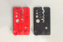
The test results are visually the model looks good, the slopes and curves are printed correctly, the lettering and the slots also look good, The printer has a good resolution. We made some approximate calculations by measuring using a vernier caliper. Since the part is so small the measurement was difficult.
A 3D printer is like any CNC machine and it runs on G code, which is generated from a 3D model by software. In our case we used Cura for slicing and converting the 3D model into G code, which the machines understand.
What happens is the that the software slices the 3d Model into a series of layers and then convert this data into a series of G code instructions that the machine can follow.
In 3D printing, we are not limited by the constrains posed in normal manufacturing techniques, hence we can cheat architecture into impossible shapes. Our assignment was to make something which cannot be made any other way.
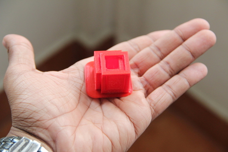
Hence I designed a cube which is locked inside an another cube. I used SolidWorks for the design, which was very simple and assembled the two cubes together. I wanted to use less material as possible, hence I put the two cubes very close to each other so that there will be less support material. After I finished designing, I exported the assembly file as an .stl so that I can 3D print them.
The reason you cannot make my model subtractively is because, it is one structure locked inside another one. This would be very difficult to make using any regular milling or casting operation, but can be done with ease in a 3D printer.
Using Cura is pretty straight forward, You have to import the .stl file into cura and select the settings you wish to print on. You have many options, the most significant investment in 3D printing is time. hence to save time and material we all decided to print small models with very less volume.
I designed a simple cubical structure in Solidworks and then assembled them to get the structure
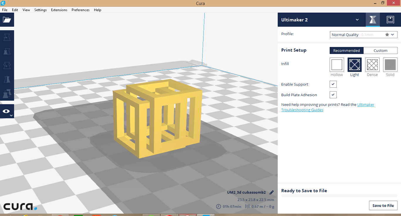
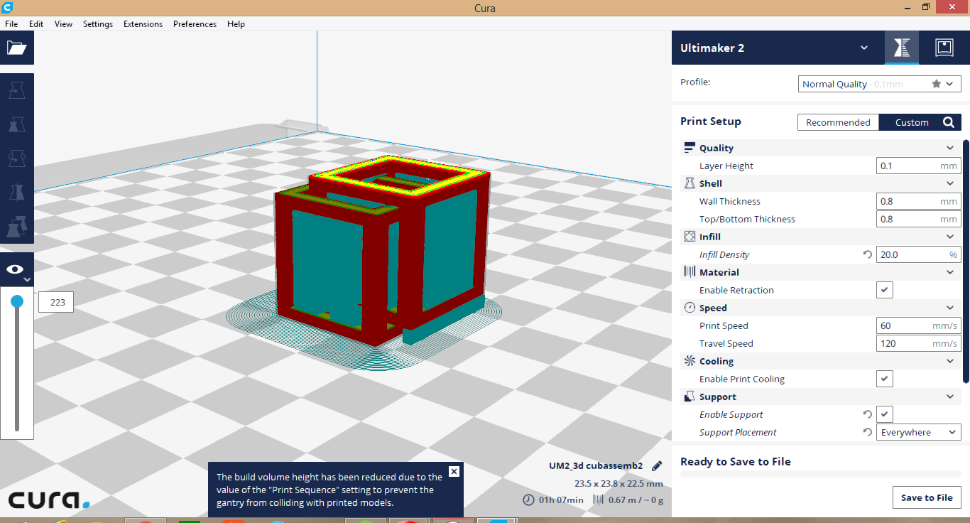
I added supports on all sides so that the printer would not print in air.
This is a time lapse of the 3D print which I tool by placing the camera on a tripod and taking a series of images at a constant interval of 10 sec.
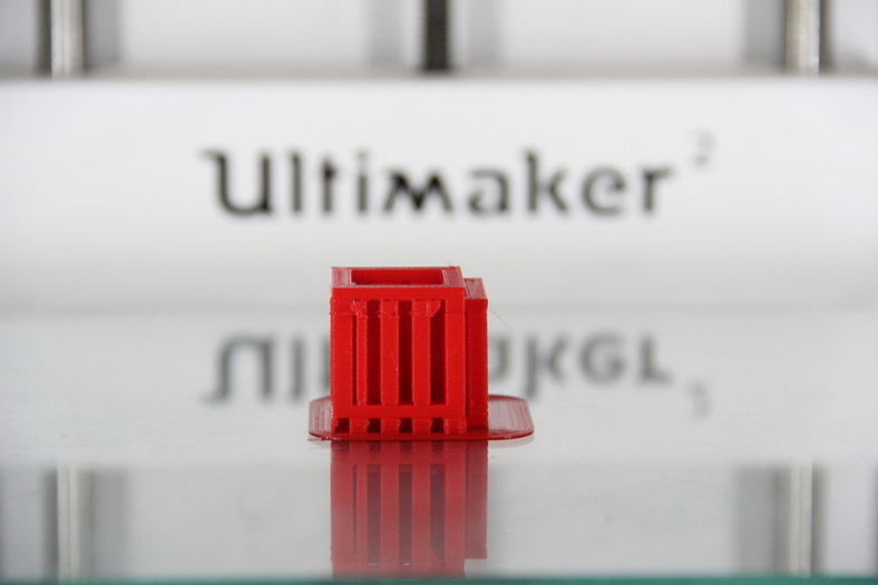
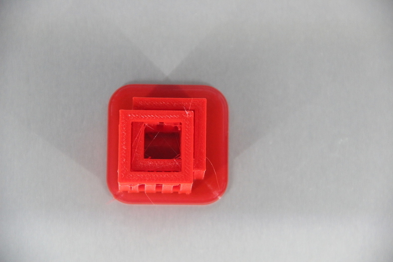
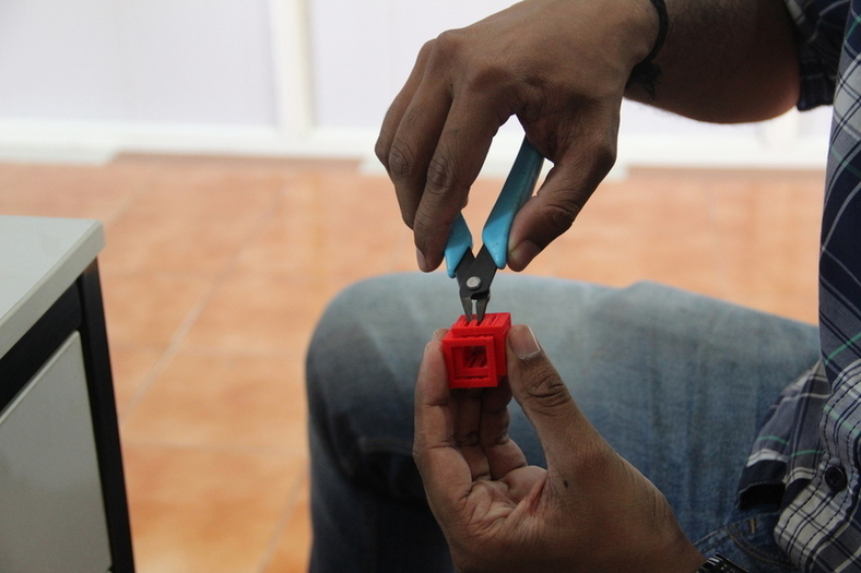
Now the next step is to remove all the supports and get the finished product. I used needle nose pliers to pry out all the support material, they are printed in folds, hence you can pull them out easily
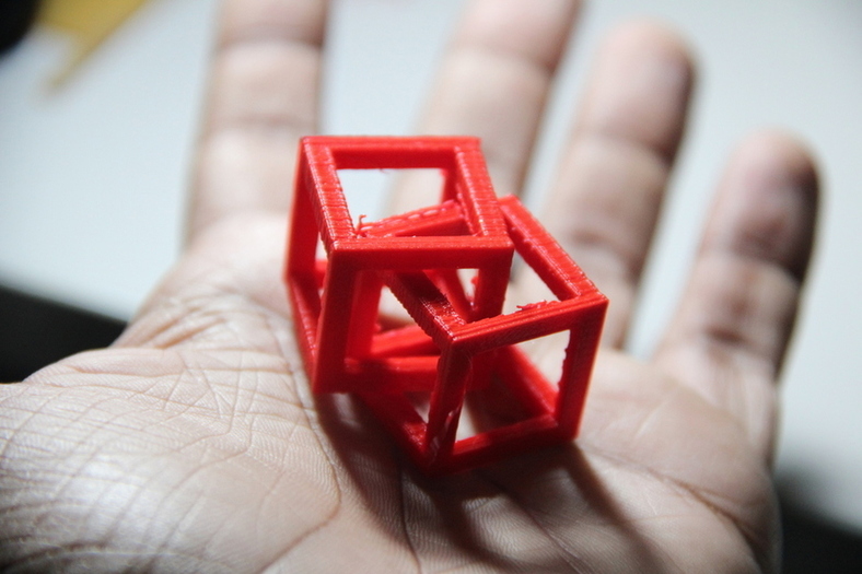
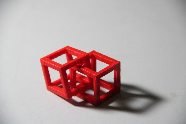
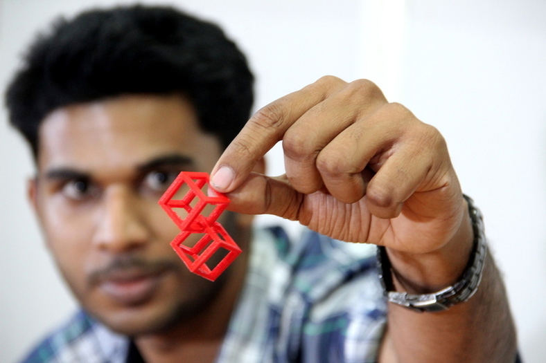
The finished product. The design was simple hence it was easy to remove the supports and the material is really strong. I learned a lot about tolerances and strength of the print material from this print and all the other prints done by my colleagues.
3D printers don't suffer from the usual limitations suffered by conventional subtractive manufacturing methods. We can add any sort of complicated feature to the part without changing much in the manufacturing part. This is the biggest advantage of 3D printing.
The main limitation I feel about 3D printing is the amount of time involved. With our current technology, we can only print so fast. I believe in the future we can see better technologies rise up.
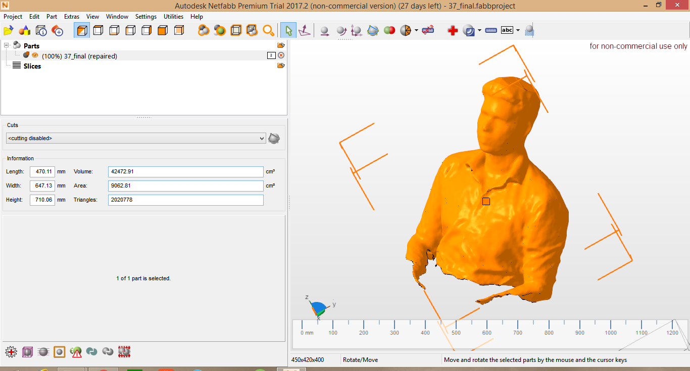
I wanted to make a 3D print of myself hence, I repaired the 3D scanned model of me in NetFabb but there was some problems as the top of my head was not scanned properly, after the repair the top of my head was flat. Even after multiple attempts at scanning, the same thing happened, the software must have some trouble with scanning the black colour of my hair.
I decided to sculpt the flat surface of my head to match with the rest of it. I loaded the .stl file into Mesh mixer and used the sculpt tools to sculpt the top of my head. I was happy with the result and I went ahead to print it.
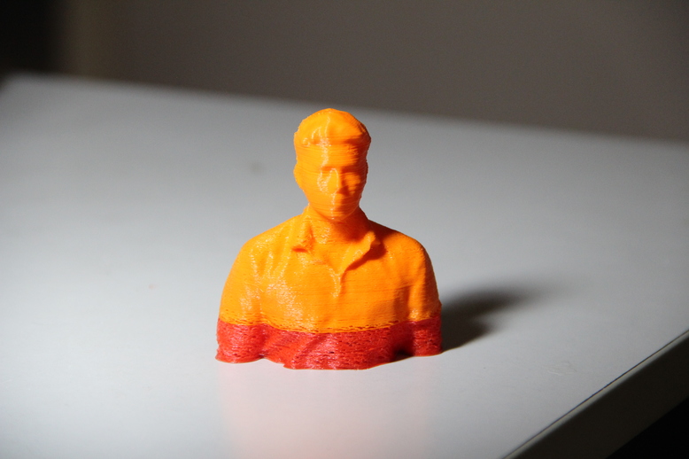
This was a lot of fun, I really like the freedom 3D printing gives you. Its unlike any other manufacturing technology. If you can design it, then you can make it. What a wonderful technology that is.
rahulsrajan.com
rahulsrajan01@gmail.com
Trivandrum, Kerala ,
India.

Technopark, Kerala, India