The vinyl cutter is a versatile machine that can cut thin sheets of vinyl, paper, or even copper sheets. It can be used to make anything from decals for laptops and cars to printed circuit boards for soft electronics.
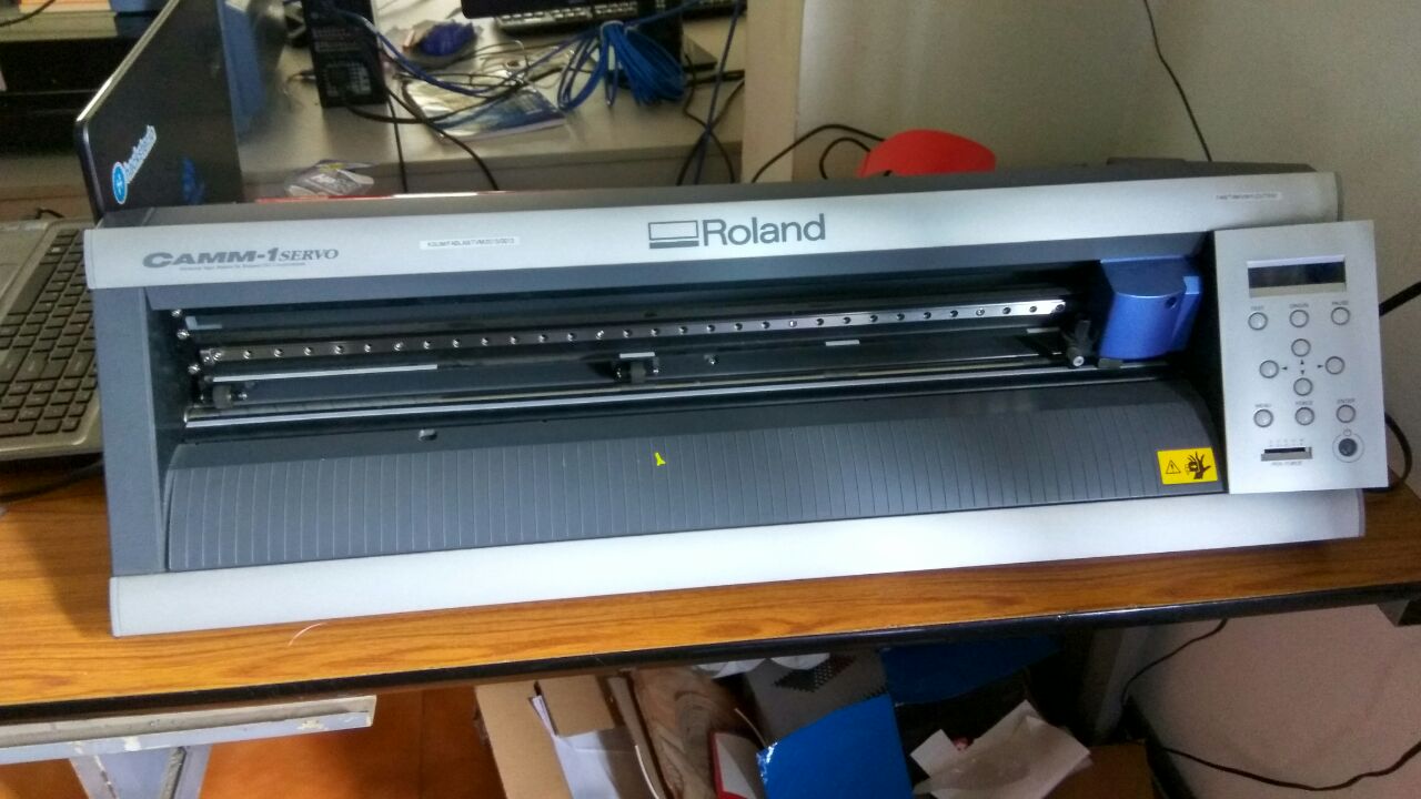
In our lab,we have the Roland desktop vinyl cutter. It has a knife which is mounted on a CNC arrangement for linear motion. The knife can rotate on its axis and the bed has rollers for moving the sheet back and forth. The sheet is cut by moving knife over it. We can set the cutting velocity and cutting force depending on the material of the sheet we are cutting.
First release the pressure plate by pressing the handle on the left side.
Load the sheet from the back.
Slide the pressure rollers to where the sheet is placed, making sure that the rollers stay inside the white lines.
Pull up the pressure plate handle to lock the sheet in place.
Turn on the machine, the tool head will move to the home position.
Select the type of sheet (Roll or Slice), click enter
The machine will automatically move the tool head to the left position of the roller, and give you the width and height of the sheet that is loaded.
Move the tool to the desired location using the arrow keys.
Press and hold the Origin button to set the origin where you want
First you need a .png image file. You can create a file in any vector softwares like Inkscape or even cut a raster image by bit-mapping it. But it should be black and white. Grey scale will not work.
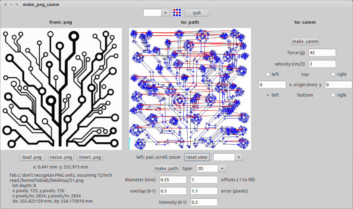
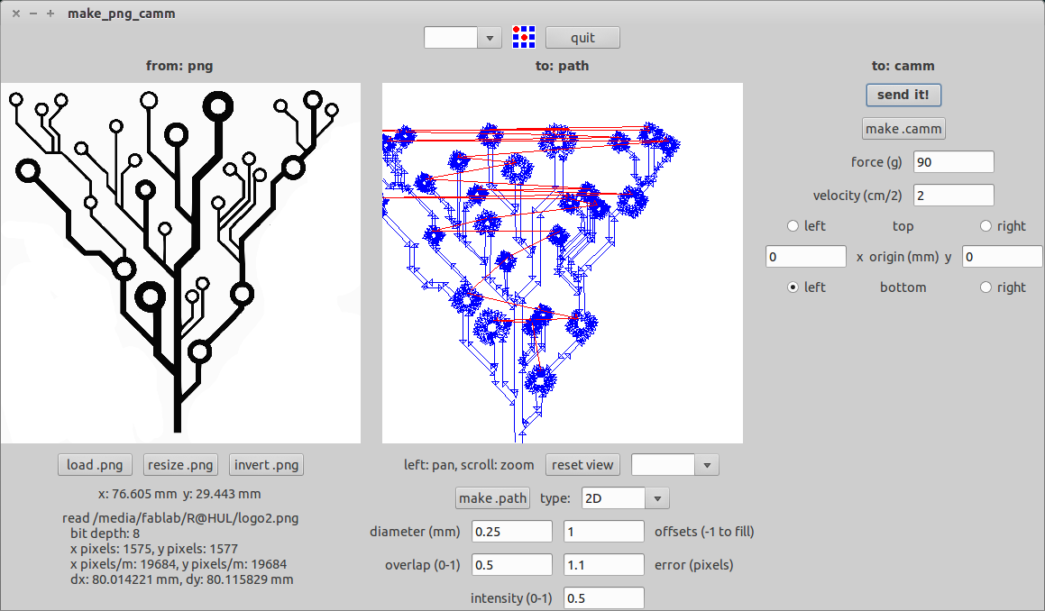
We use the fab module to convert the .png image into the tool path. Go to the fab module and select the input format and the output process and click make_png_camm. A new window will pop up. Now click the load png button and select your image. Now your image will be displayed. You can resize the image to the size you want and click make path. Now you can see the cutting path of the tool.
You can leave the rest of the settings as default or edit them depending on the material. For cutting vinyl, I changed the force to 90g and left the rest to defaults. You can also change the cutting velocity depending on the size and intricacy of your design.
Click make .camm button and click send it, now the machine starts cutting.
I wanted to make a custom decal for my laptop. I loved the idea of a circuit board like pattern, as an extension of the Intel and Nvidia logo, already on my laptop. I searched online for good circuit board graphics and found an image I liked.
![]()
I edited the image on Gimp, since I was familiar with it from the previous week. I cropped the image to fit the size of my laptop. I wanted to measure and include the openings for the two logos directly on my decal, hence I can cut them accurately using the machine. But that turned out to be very difficult. Hence I switched to an simpler plan.
I used Inkscape to convert the image into a bit map, by going to the path>trace bit map option. This gave me a vector file of the image.
When I tried to use the fabmodule with the original png image, the path was not correct, It seems there was some grey areas in the picture, hence I converted the image by bit-mapping it(uncheck smooth option) in Inkscape. Now the grey areas were gone, and the path showed up correctly on the fab module.
I’ve cut out the full image on the vinyl cutter using the fabmodule to convert the .png image to the .camm format. This was really a trial cut to learn how to properly cut and apply vinyl graphics. And like many things, you learn from failure. You have to pay attention to the values you input to the machine and double check your dimensions.
I measured the space on my laptop and fixed on a size of 8x8cm. Since this was a test cut, I cut the full image on a single sheet of red vinyl.
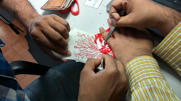
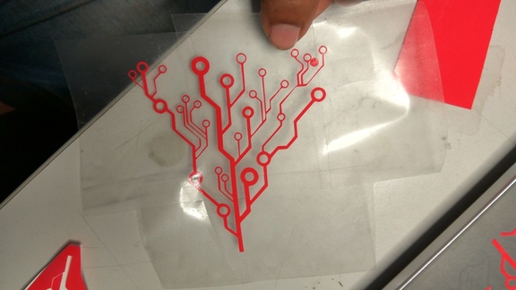
Even though the cut went smoothly, removing the graphics from the paper was harder than I thought. It takes patience to meticulously remove each strand of vinyl from the rest.
When I tried sticking it on to my laptop, it did not work, the tape was too strong and the vinyl peeled off my laptop. This is the result.
I learned a lot form this cut, about what not to do.
Mistake#1 Using Masking Tape directly.
The glue in the masking tape is very strong, even after I dusted it with some talc, and this is what ruined the application of the vinyl. Ideally you want the glue strength to be less than that of the vinyl and the backing paper, so that it is strong enough to lift the cut portion, but weak enough to let go of it, after you stick it on a surface.
In my first attempt, removing the vinyl was so hard that I got my friend Syed to help me with it, but In the end the masking tape won.
What worked for me was cello tape, along with talc to remove some of the glue.
Mistake#2 Intricate design.
The cuts were so close to each other that separating them from each other took a lot of time. If you are planning to go intricate, scale it up a bit.
Mistake#3 Not cleaning the surface of laptop properly
Even if you wipe the surface, it may have oils from your skin. In my initial attempt the vinyl did not stick to the surface properly. The next time, I used a cello tape to remove the dust and oil.
![]()
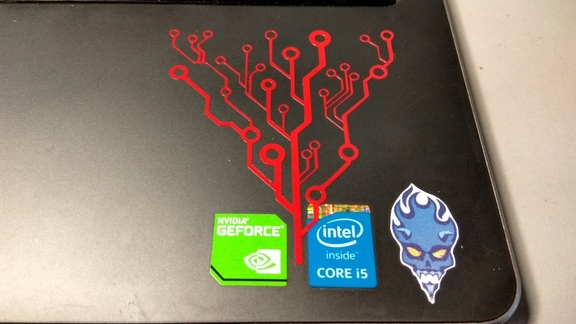
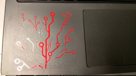
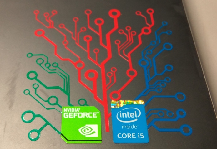
This time I split up the design into 3 parts so that I can quickly cut and try different variation of them if necessary. I got better luck with cello tape, I was able to transfer my design to my laptop successfully. I cut the three parts in 3 colours so as to match the existing decals on my laptop, and meticulously removed the vinyl and transferred it to the surface.
Note: when sticking together different parts of the design, be sure to not let the tape touch the vinyl already stuck on the laptop, trim the edges properly.
After hours of cutting and careful peeling and sticking, this time I was successful.
I’m really amazed by what this machine can do. It allows you to cut intricate parts for machines, like gears, press fit assembly, pulleys, etc and can do it in a very short time. It is also very dangerous and should be treated with care.
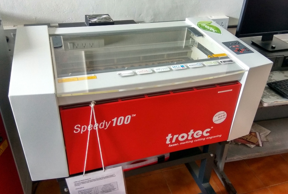
The laser cutter works by focusing a high energy beam of light in a small area to vaporize the material there. In our lab, we use the Trotec speedy 100, it uses a Carbon dioxide(CO2 ) laser for generating the high energy beam. The laser beam is generated at the back of the machine, which is then diverted by a system of prisms. The beam is then focused and moved using a CNC arrangement that allows for rapid 2D motion.
When you start the machine, the bed moves to the bottom and the cutting head moved to the home position.
Load the sheet on the bed.
Bring the bed up close to the cutter head.
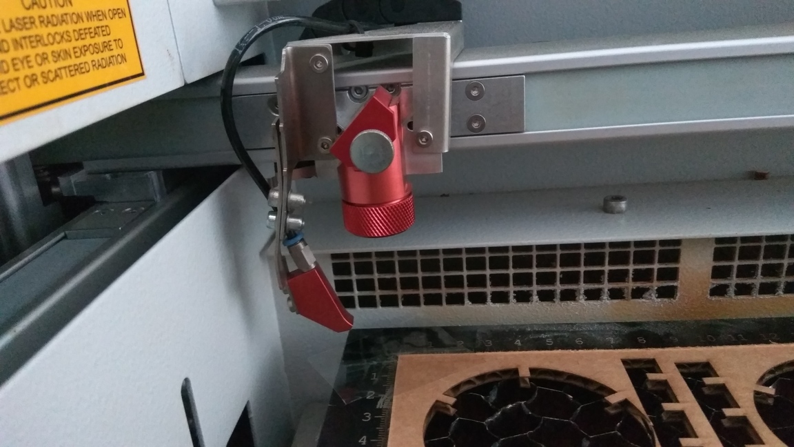
Manually focus the laser by using the spacer provided, hang the spacer on the notch in the cutting head and slowly raise the bed, until the spacer falls off.
Set your origin and start cutting.
The laser cutter needs vector paths to tell the cutter where to go. It can also etch raster images. You need a vector graphic software like Inkscape to draw the path. The laser cutter works on the basis of colour. Red(R255) means cut and Black means engrave. You can set different colours and give different values of power and speed to get different depths for etching and cutting.
In Inkscape, if you want to engrave an image, then go to Path> Trace bitmap. There are three modes Brightness Cutoff, Edge detection, Colour quantization. Ideally you should try all three modes and see which fits the image.
Once you have the desired vector image, right click and select fill and stroke, and give the colour red to the paths you want to cut and leave the parts you want to be etched as black.
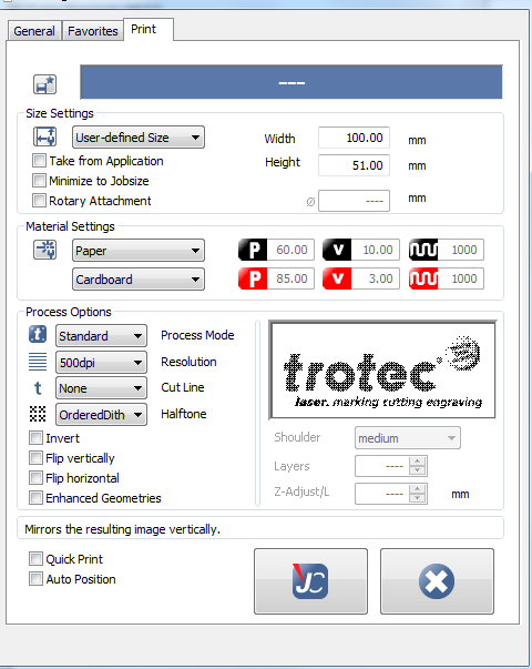
Set the width and height of the image, and set the document properties to close to that of the image you want to engrave. Now click print.
Under preferences, select the type of material and set the width and size of the print document. Done, now click print. The job will be transferred to the job handling driver of the laser cutter. Once you focus the laser and set the origin, click ready to connect with the engraver. Start the air filter and click print.
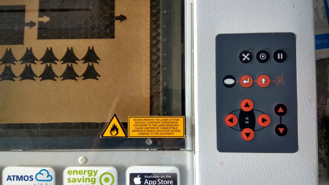
IMPORTANT: Never ever leave the laser cutter unattended, in any situation.
Never start cutting without first turning on the Air filter. Cutting releases harmful fumes which are hazardous to your health. After cutting only open the door after 10 to 15 seconds so that the fumes are properly ventilated. Never cut PVC and any other material you don't know the composition of.Our assignment was to find the different values of kerf and the power settings for various materials. We did our experiments on wood and acrylic.
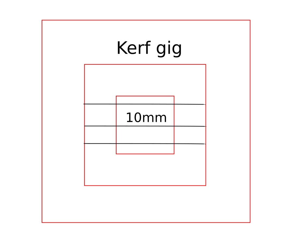
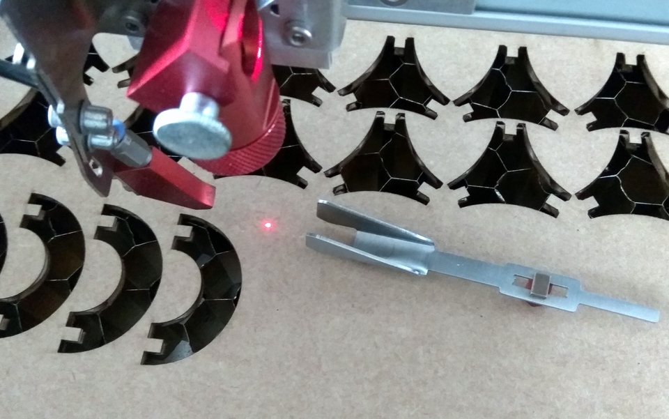
We started by find the kerf of the material. For finding kerf we drew a couple of squares and cut them out. We then measured the inside and the outside dimensions and divide them by two to arrive at the kerf. We cut out multiple squares and took a couple of reading on each one and averaged out the result.
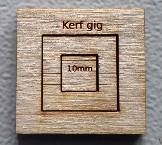
Three reference lines are etched on the surface to ensure accuracy while measuring.
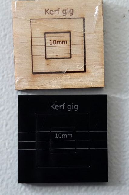
Our values for cutting Acrylic are
Power=100 Speed=0.8 frequency=1000Hz The values for Etching are Power=80, speed=10 frequency=1000Hz.

What we found out is that, for wood the kerf value wood is 0.325mm and in acrylic is 0 .244mm
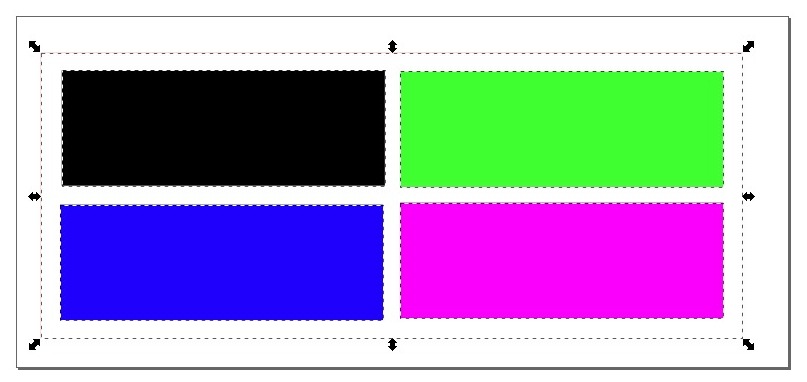
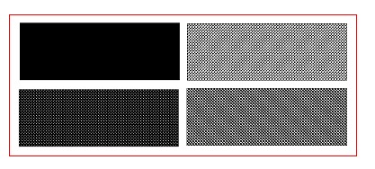
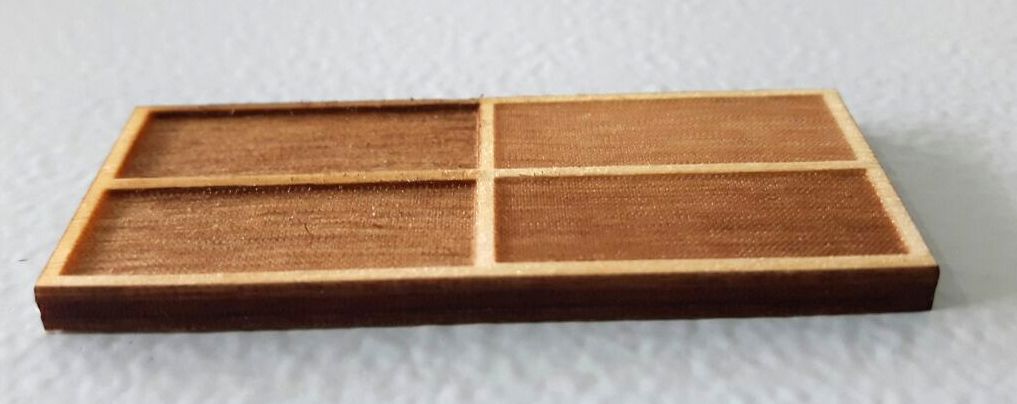
In our next experiment we tried varying the laser power for etching to get different depth. In our laser cutter Red(R255) is set to cut and Black(0) is set to engrave. The power and speed are set after many experiments on various materials.
Our values for cutting craft wood are
Power=90 Speed=1.50 frequency=1000Hz The values for Etching are Power=60, speed=10 frequency=1000Hz.
For different colours we set the values for etching as 80, 60, 40, 20 etc and kept the speed as same. We got different depths based on the power.
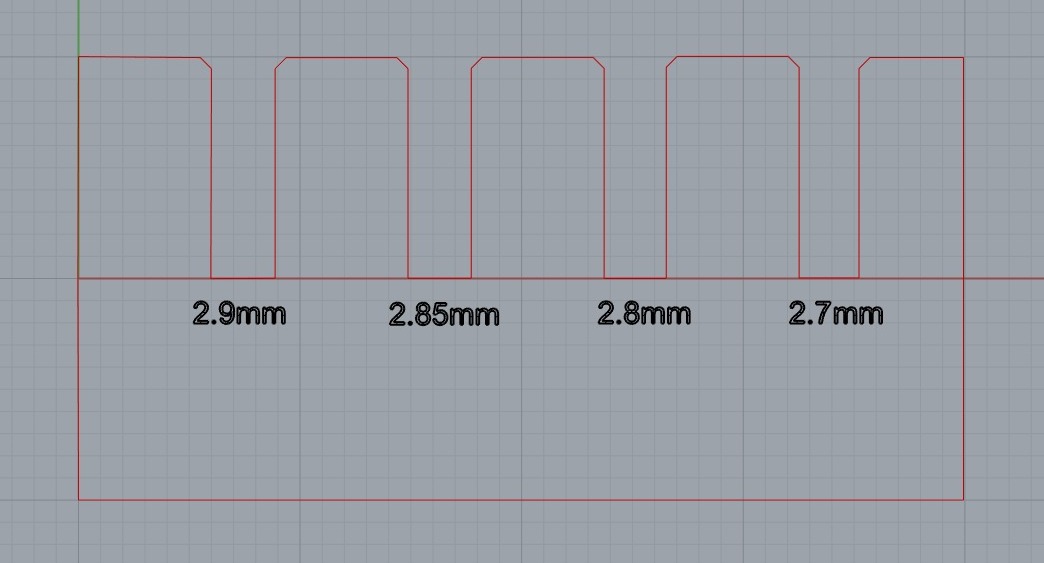
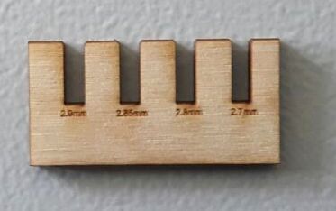
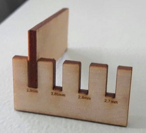
We made a craft wood comb to check whether the kerf we got was correct or not. For 3.1mm craft wood, we made slots, from compensating for the kerf value (2.9mm) and downwards in steps of 0.05mm

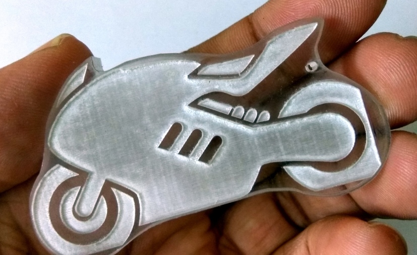
I wanted to make a key chain out of acrylic for my bike. This would be my first experiment on the laser cutter. I looked online for a design and found an image of a racing bike. The design was simple and I imported it to Inkscape to edit it.
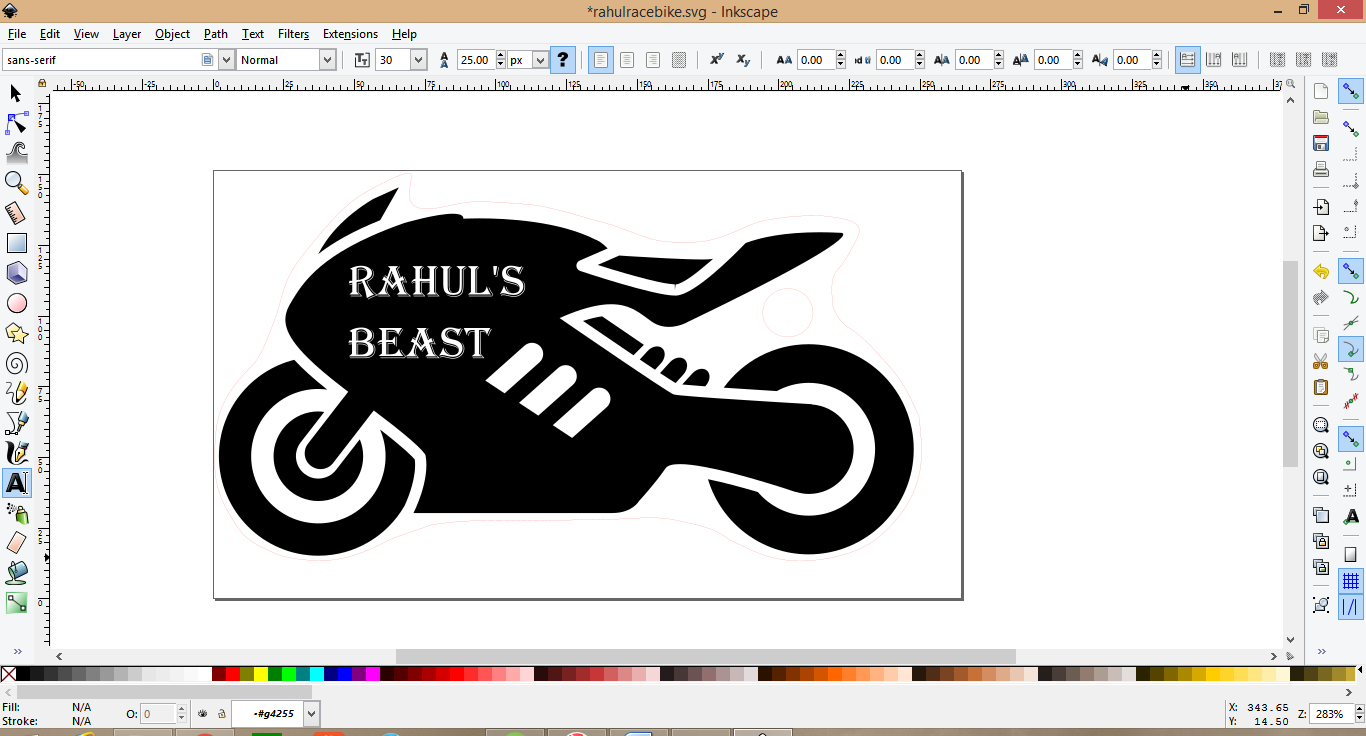
I used the Bezier curve tool to draw a cutting path around it as neatly as I could. I changed the stroke of the cutting path to red and the line width to 0.01mm. Now I set the width and height of the image and clicked print. In preferences I set the material and size and set the document width and height. After clicking print, the job was transfered to trotec job handling software.
I turned on the machine, put the acrylic sheet, focused and set the origin. Then I clicked ready to connect with the machine, started the Air filter and click print to start cutting.
In my first attempt, I did not set the document properties correctly, hence my etching was clipped at the edges, for some reason the cut happened correctly.
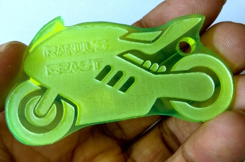
In my second attempt, I double checked the sizes and added my name to the etching. This is the finished result
I was amazed by the various designs for press fit kits. You can build anything you can imagine. I was lost for a while thinking about what to make, I loved the idea of bending wood. Then I decided I would start simple and progress to more complicated ones.
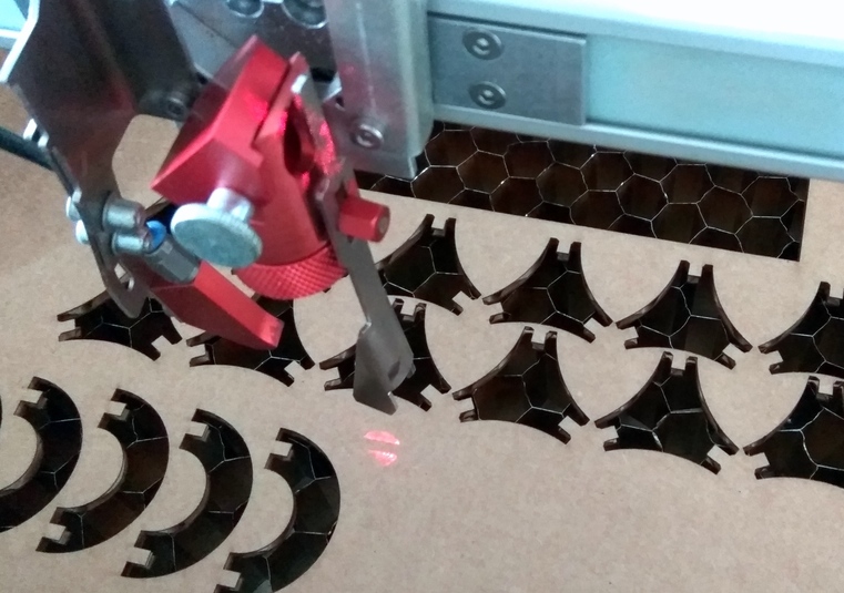
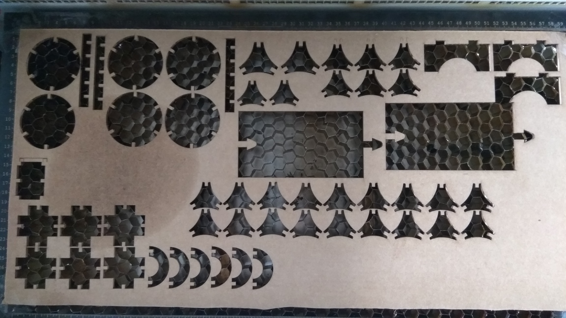
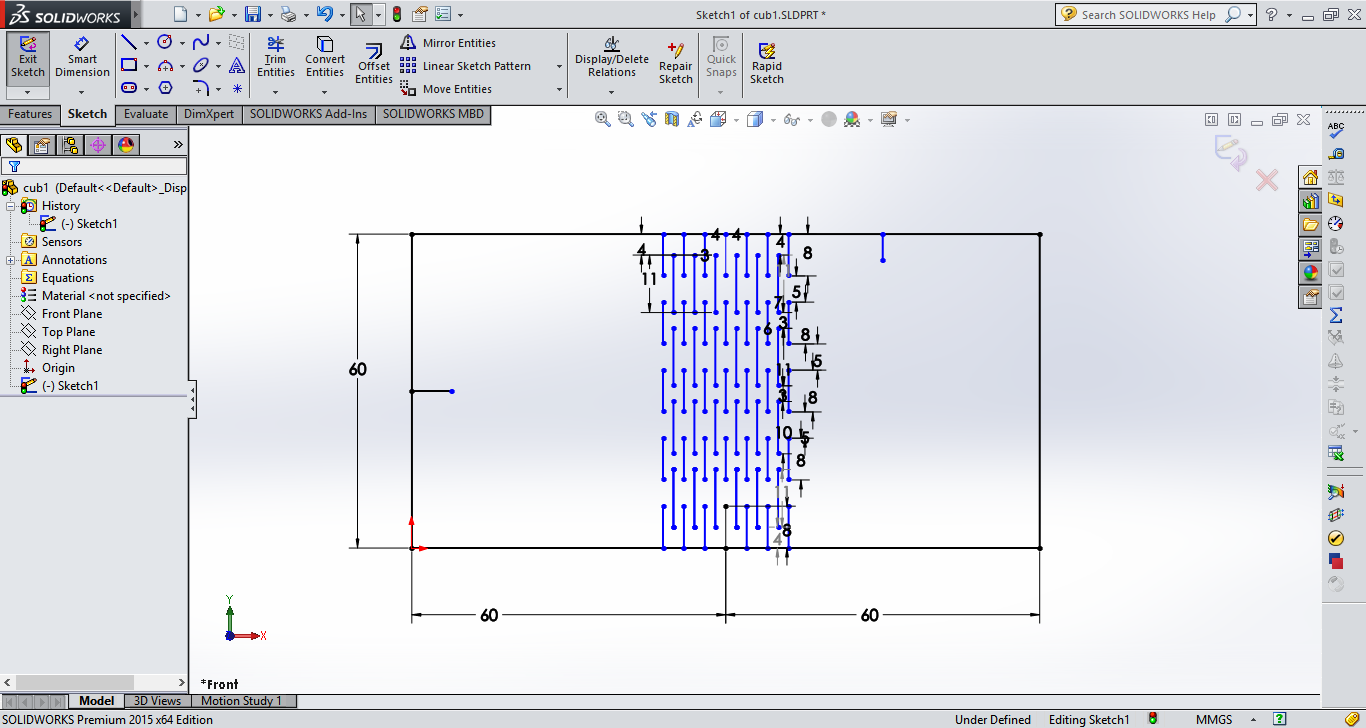
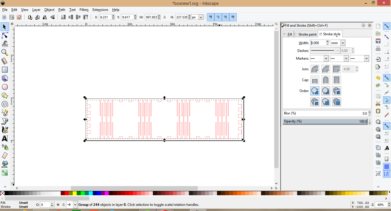
I decided to make a simple triangular modular element, which can be replicated many time, and combined to make unique designs. I used SolidWorks to draw the sketch and extruded it. The design is parametric and all the dimensions can be changed later to fit various materials of different thickness. I then exported the file as a .dxf file and opened it in Inkscape, I aligned the design and changed the colour to match the cut line(R255) and cut out two test pieces.
They fit perfectly. In the next try I nested multiple copies so that I could batch print them.
I assembled them into a 3D shape.
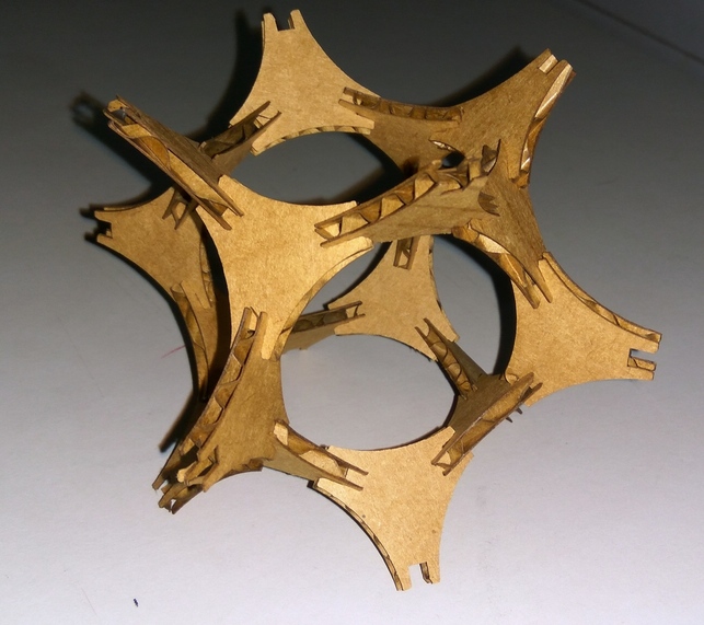
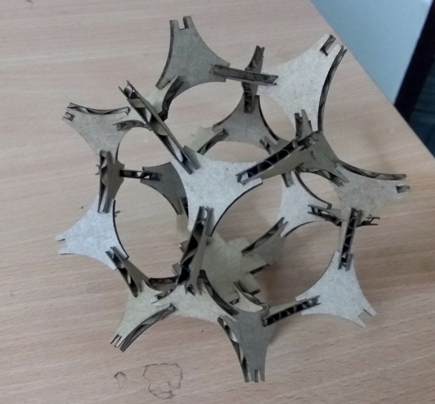
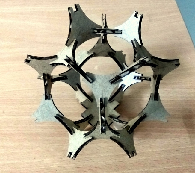
Note: The cardboard I was cutting on averaged a thickness of 3.8mm. Hence accounting for the kerf I put the hole width as 3.5mm. This gave a good fit.
Kerf bending is the technique by which you cut slots into the wood to create beams, which allow the wood to bend easily. What happens is that these cuts turn the solid piece of wood into a series of interconnected beams, and these beams bend by torsion. I read online many details on how to build them, there are many patterns to choose from, I started with a simple one.
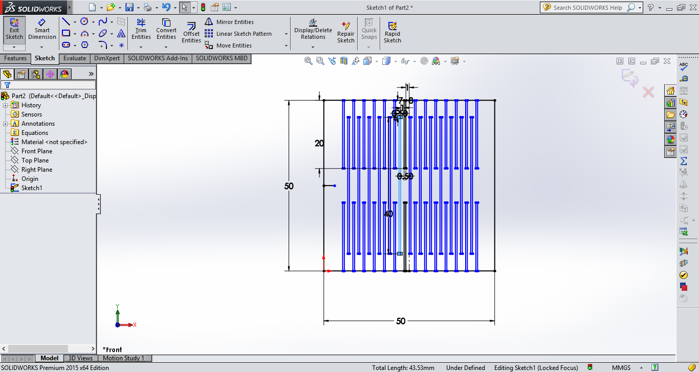
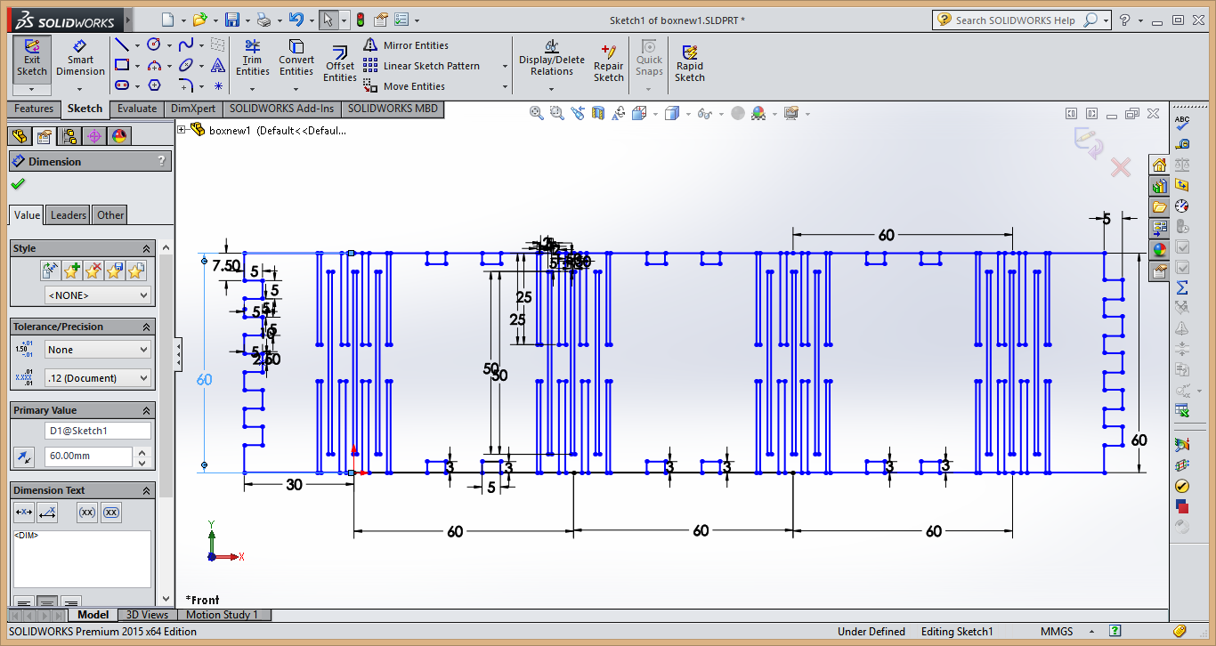
I didn’t want to just copy the pattern from the internet, I wanted to know how they worked, so I began drawing my own in SolidWorks. I wanted to know which parameters influenced the bendability and the structural strength of the bends.
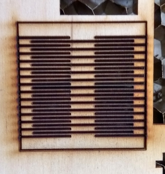
Looking at the images from the internet, I had a basic idea about where the hinges should go, I tried my best to understand the shape and draw it in Solidworks. This is the result.
There are several problems with this design, The cuts are not long enough to allow for good bending radius. The bend is very stiff, I could probably bend it about 60 degrees without any problems, but after that the wood started cracking. It is good when you need only a slight bend and want to preserve much of the strength of the wood.
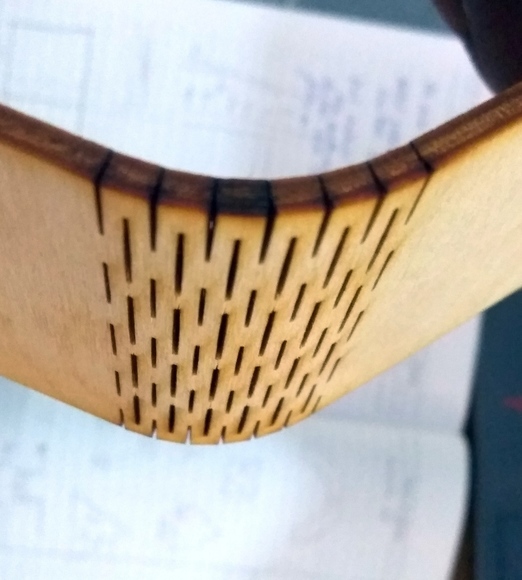
I learned a lot from my last cut and this time I increased the lengths and widths of the cuts for added bendability.
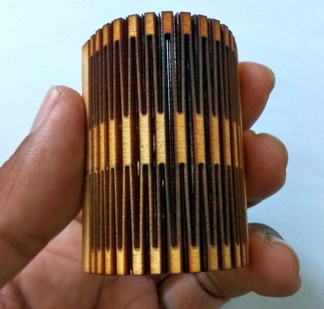
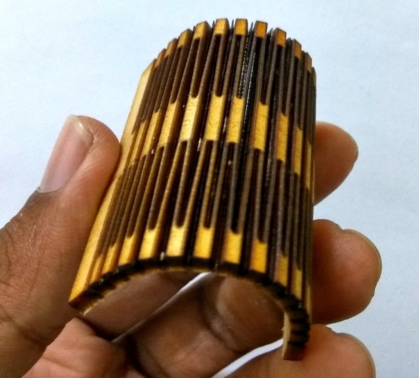
The cut is not perfect but the hinge works. Bendability is very good, but the joint is very fragile because all the cuts are very close together. It is good with torsion, but week in longitudinal stress. I’m really satisfied with this hinge. I will try some variation and different patterns of this in the future.
Yesterday I had some success with kerf bending, so today I wanted to take it further by designing and building my own press fit wooden box. I wanted it to have curved edges and a removable top and bottom. All of which will be held together by finger joints.
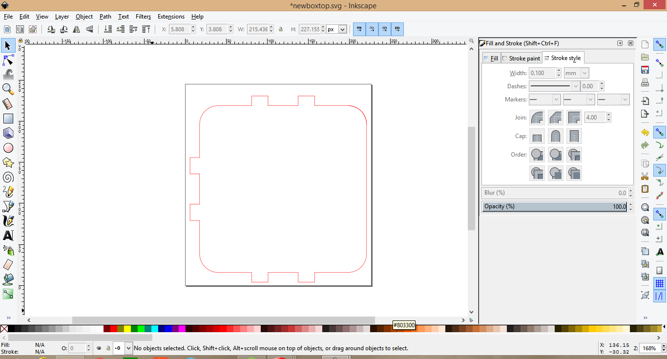
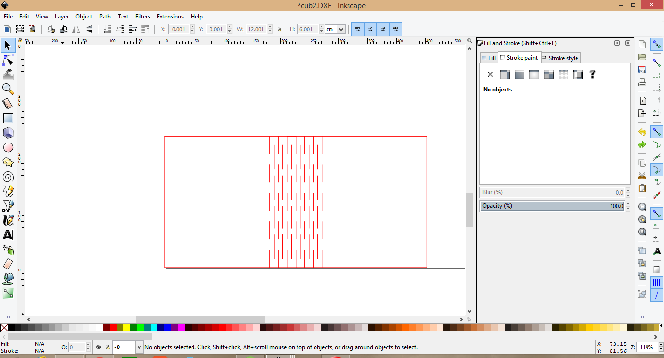
I started working on my design in SolidWorks and quickly realized the challenges I had to face. I need to draw from scratch a kerf bending pattern, that would fit well with this shape and size. I set about to enlarge the previous pattern I had created yesterday. One thing that constantly bugged me was that the pattern I was drawing was not really symmetric in the x-axis. It would be slightly longer on one side. I drew one pattern and mirrored it to the other sides.
Designing the top plate of the box was carried out simultaneously, I had to draw one part in one file and then create the corresponding path on my side sections. Drawing like this is hard, there are a lot of things you have to keep in your head to simultaneously switch between drawing one part and the other.
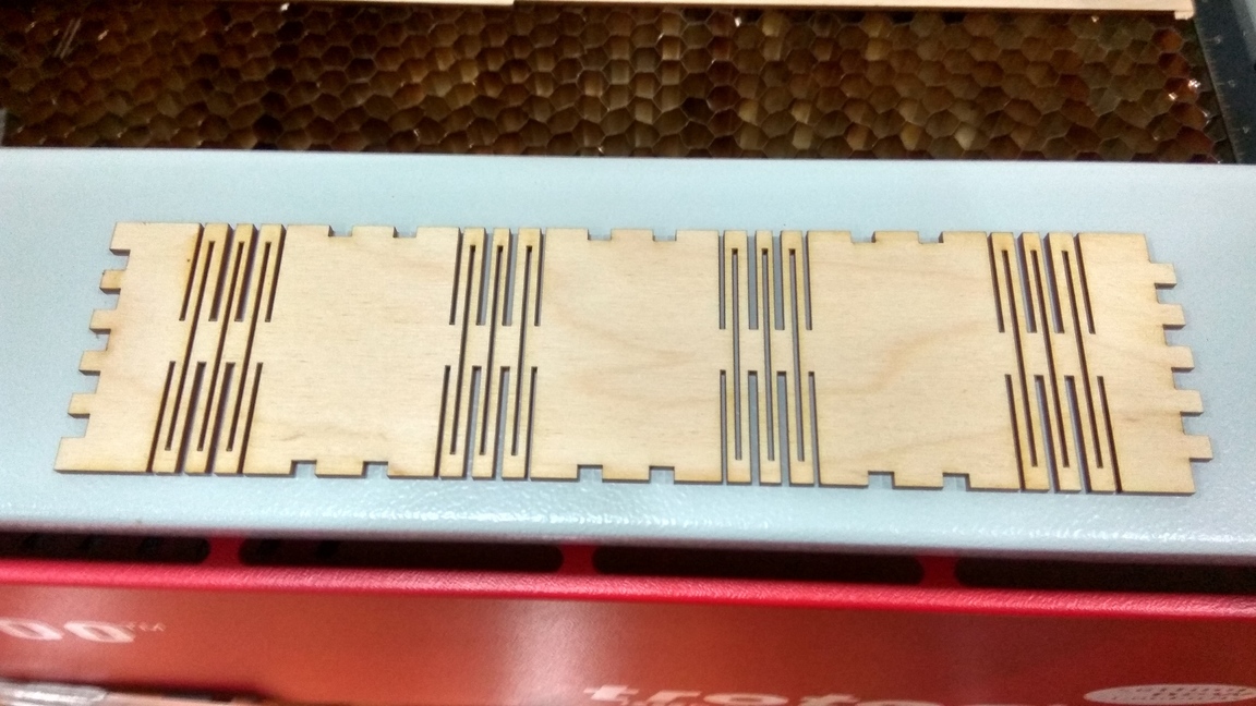
In the end I created what I thought to be the right design and correct dimension. So I cut out a test piece in cardboard.
The hinge looked good and I tried assembling the pieces together, I thought it fit good enough in cardboard, Hence I made a piece wood.
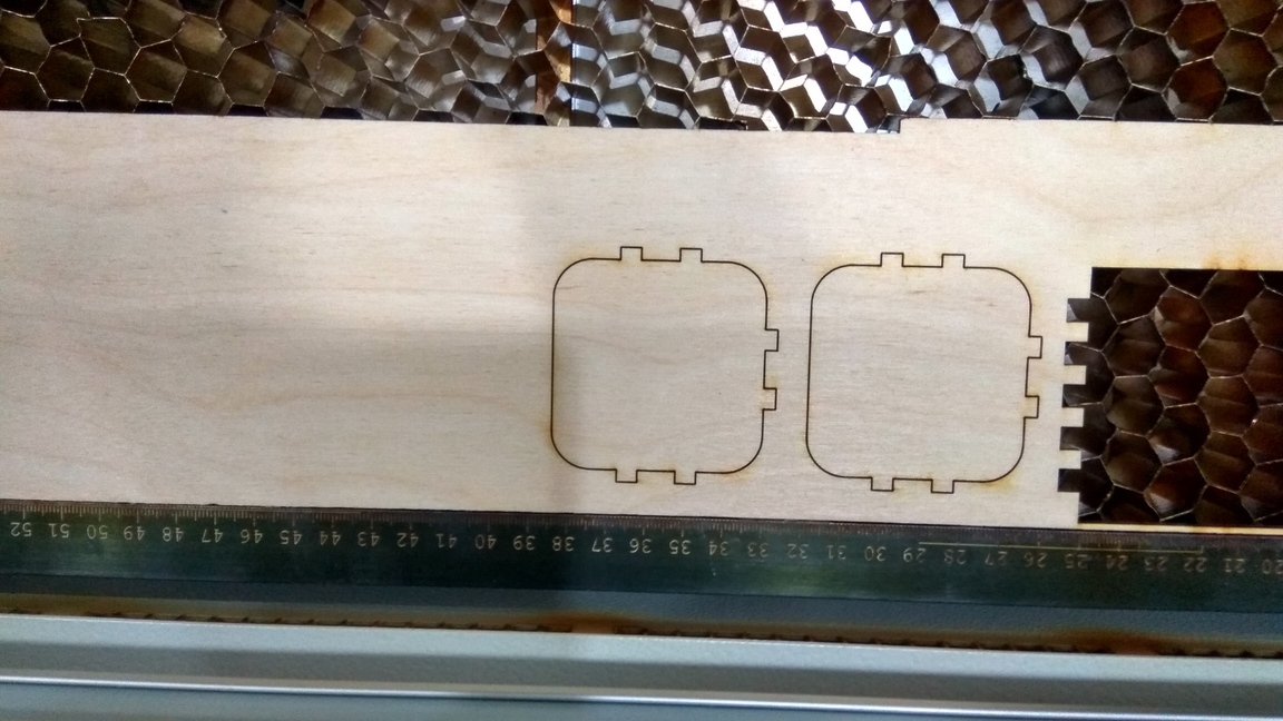
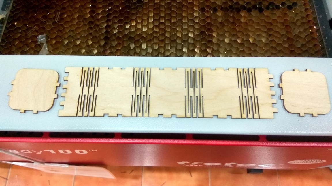
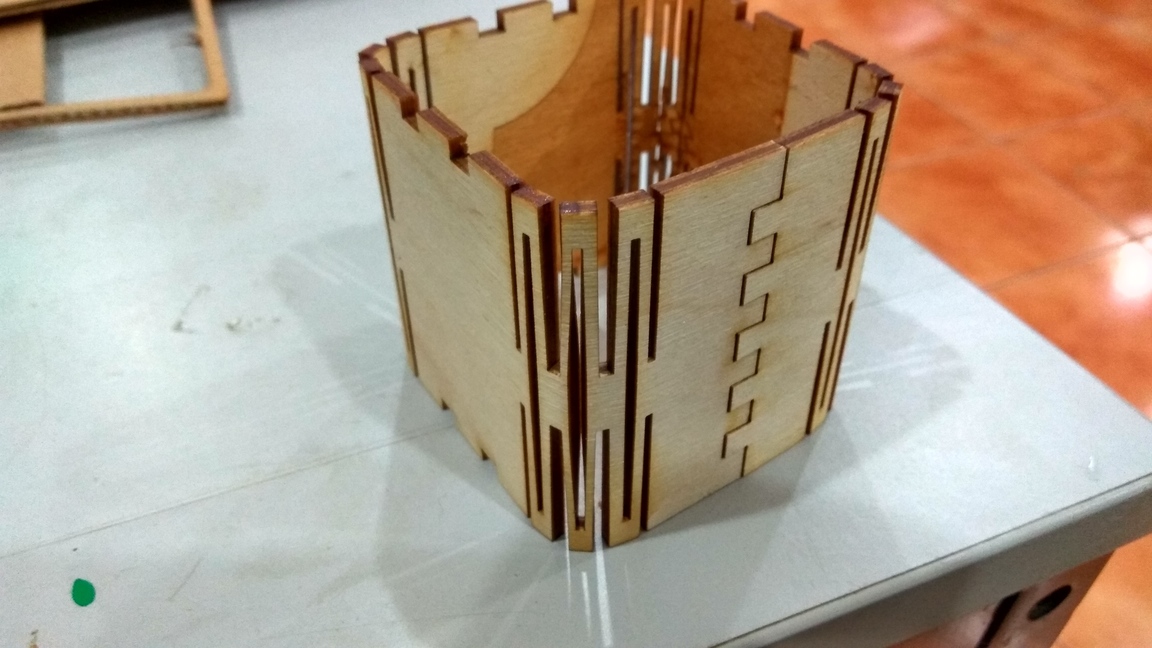
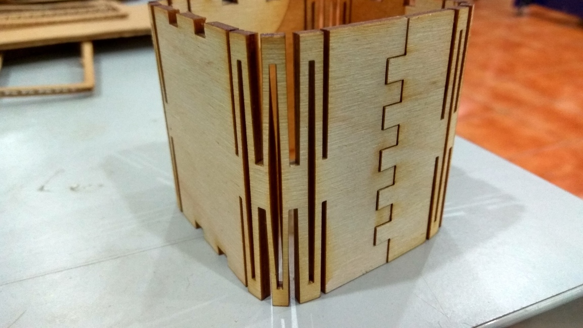
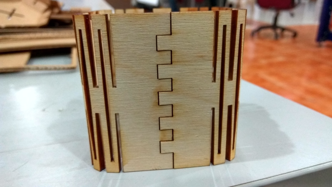
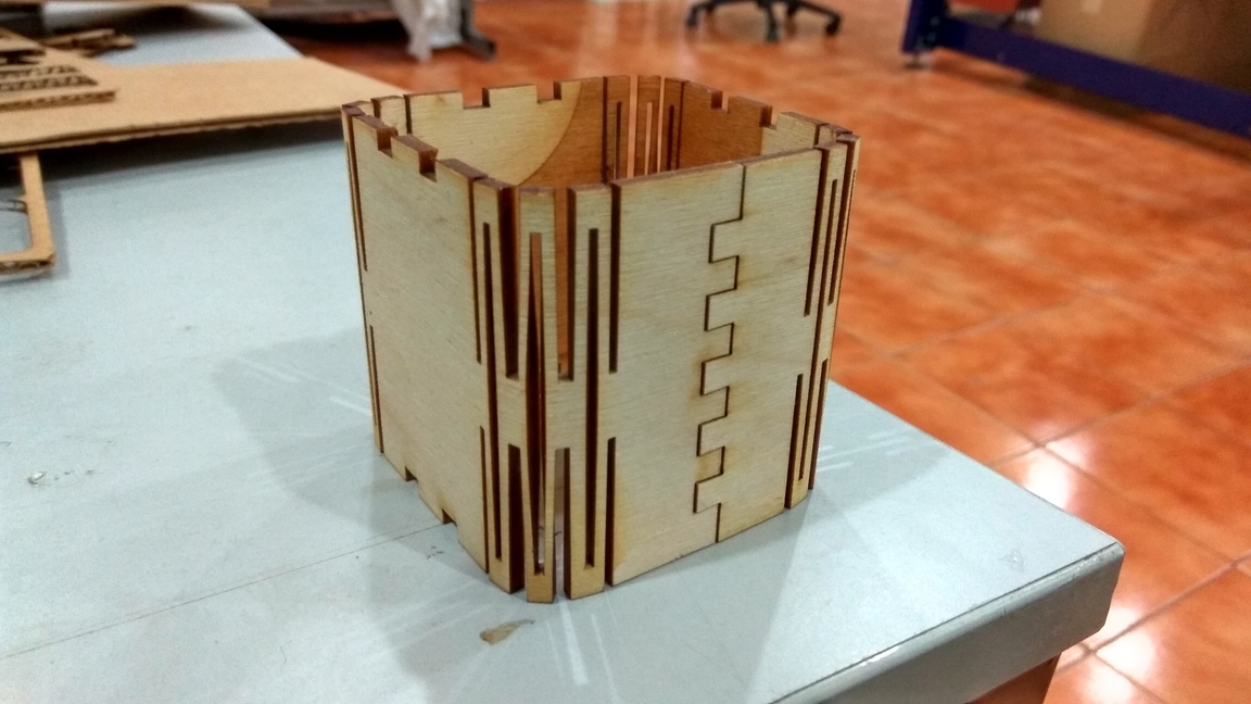
I have made some dimensional mistakes in the desgin of the top and bottom plates, they were not apparent to me in the cardboard model but in wood, I realized the mistakes I made. There are many problems with this design, a few of them being, The dimensions were not accurate. The kerf bending pattern is not optimal as it puts a lot of strain in the middle member.The design of the top and bottom plates need to be improved.
I learned a lot by designing boxes myself. I struggled when drawing the sketch of the curved box from scratch, This was the first time I was designing foldable geometric structures. But it was fun figuring out what goes where and why, and I loved every moment of it.
What I would have done differently Change the kerf bending pattern. Made sure the holes aligned with the top plates.When adding tolerances, make sure that you have added them bidirectionally, you don't want the tolerances compounding together and shifting the sketch to one side.
rahulsrajan.com
rahulsrajan01@gmail.com
Trivandrum, Kerala ,
India.

Technopark, Kerala, India