In this week, we are trying out the versatile art of molding and casting. Even though 3D printing can be used to create molds and cast material from them, the traditional method of creating a mold and casting replicas of your product still remain relevant.
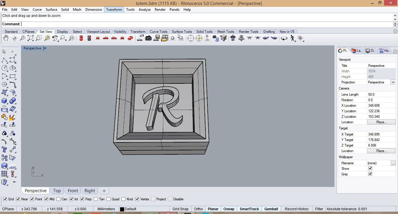
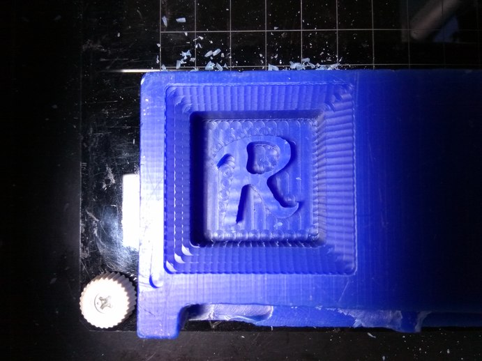
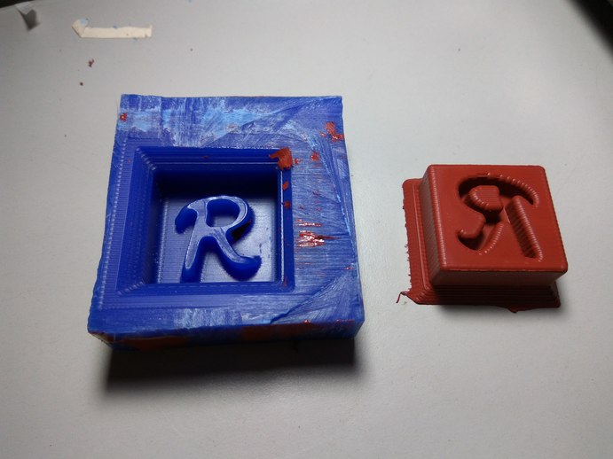
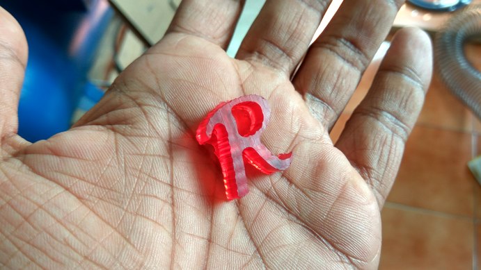
Since this is the first time I have tried to cut a 3D profile, I wanted to learn more about the software and how the machine will behave when cutting a 3D profile. So I created a simple raised letter 'R' mold in Rhino. I then proceeded to create the side walls on it so that we can mill it out in wax.
I realized one thing when I proceeded to machine is that I had forgotten to loft the edges of the corners of the rectangular box. The reason this is important is that you have to take into account the depth to which your end mill can safely cut without the spindle hitting the wax mold of it. This is really important as i will realize soon enough.
I then took some measurements like the cutting depth of the end mill and the depth of cut of my mold and found that it would be okay to cut with it.
There are two types of milling operations happening when cutting a 3D file. One is the Roughing cut where the majority of the material is removed. in this operation the objective is to remove as much material as possible in the shortest amount of time. Hence The tool follows a raster patterns, gradually chipping away large volumes of material, while leaving most portions of the pattern intact so that it can be milled later.
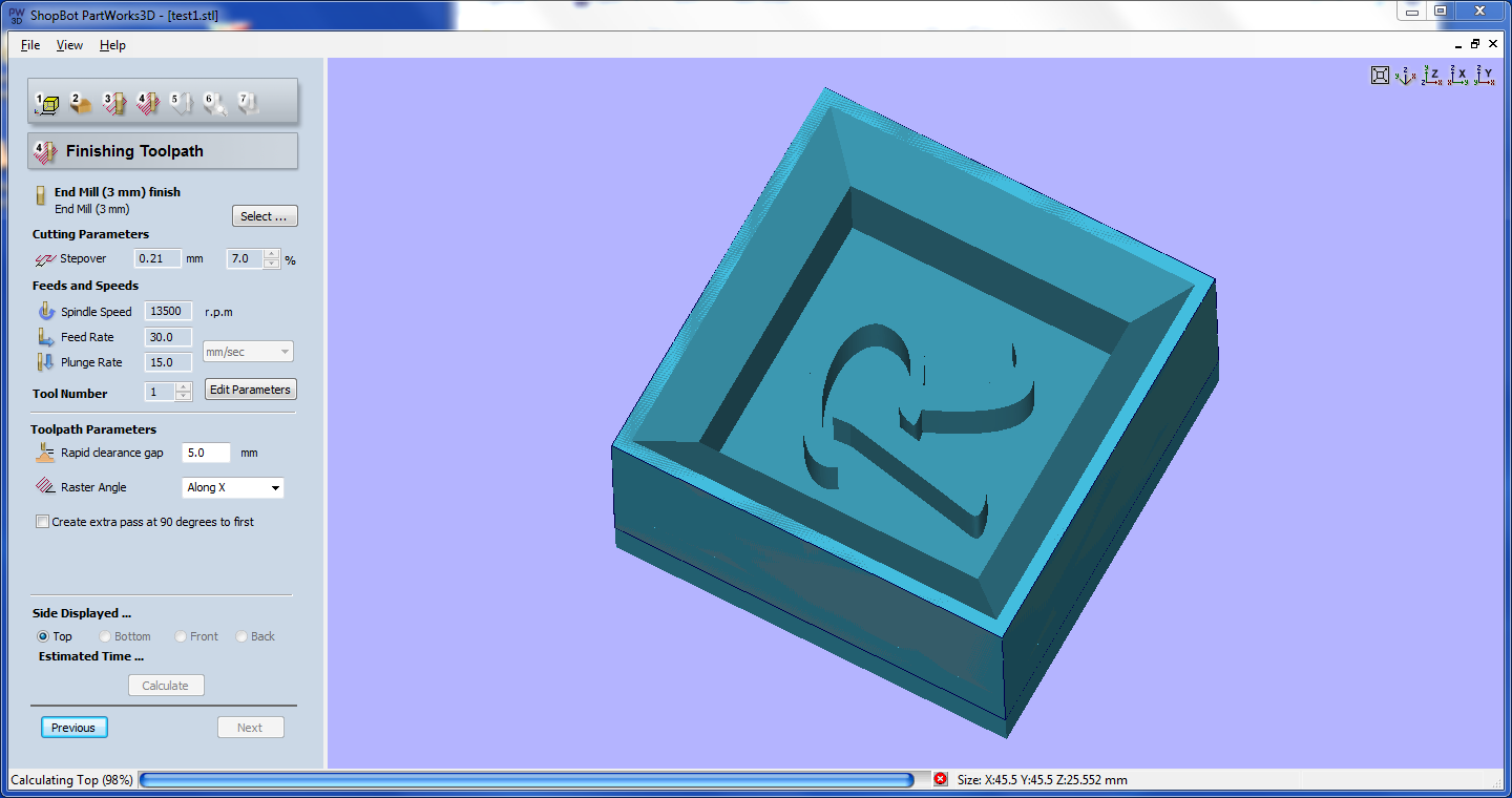
The next type of operation is the Finish cut. in this operation the objective is to get a smooth surface finish. Since the roughing operation has removed the majority of material, here we will slower the feedrate and decrease the stepover distance.
The stepover distance is the distance which corresponding cut lines overlap. That means a stepover of 100% (or the size of the tool diameter) will mean that the next cut will happen at an offset of the diameter of the tool. A step over of close to 10% (ideally 7%) is required for good surface finish of the pattern. I cut mine with a stepover of 15%.
I used the fab mods to generate the G-code to run Modella. Here the input file is an STL generated by and CAD software and the output is an .rml file which is sent to the modella.
The procedure is same as in PCB milling but here you are working with a 3D file. The software generates a .png file from the .stl file, where the depth of the cut is measures by the degree of lightness of the .png file. The next step is to select the type of operation, for Eg- mm 1/8 rough cut. Then set the tool parameters, and click 'make .rml' button. This will create the tool path. Now position the tool head and start milling.
The machinable wax was stuck on the bed of Modella using double sided tape. I put in the 1/8 end mill for milling the wax. And once the origin was set and the Z-axis zeroed. I began milling.
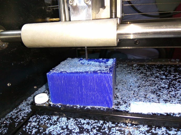
The program showed a time of 10mins for the Rough cut. A peculiar thing that happened to me was that the machine started cutting at a different point than which I had set the origin. I don't understand what had happened. The cut was going good hence I did not stop it, I though that it might be something wrong with the model I created in Rhino and I might have misplaced the origin.
The rough cut was proceeding at the far end of the block. I knew a portion of the top edge would break but since its a test and I have yet to see how finish milling works, I proceeded with the milling operation.
The rough cut finished with agreeable results, Then I proceeded to do the finish cut, I cut the finish cut with the same bit since there are not many smooth curves in my model and I did not want to waste time changing the bit. Everything went smoothly in the Fab modules until I generated the .rml and began milling.
For some mysterious reason it began cutting from the origin which I had originally set. I don't understand why this happened as I have changes nothing in the software and the input is the same .stl file. The machine tried to do the finish cut from the correct origin, thankfully I had a strong 1/8 inch bit so it held up against the excess feed rate. I quickly stopped the machine and checked out what I did wrong.
There was no change in the input file, both the cuts started from the same origin,and no settings were changed. Well there have always been ghosts in machines. So I'll leave it at that.
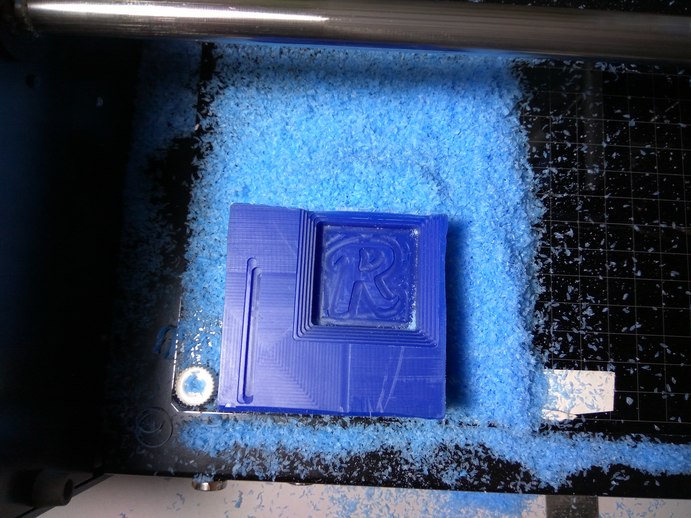
The next time I tried with a similar setting and the only change I made was put a new block of wax on the Modella. I gave the same settings and this time the modella responded well and the cut started from the origin. The rough cut came out beautifully. I liked the finish of it.
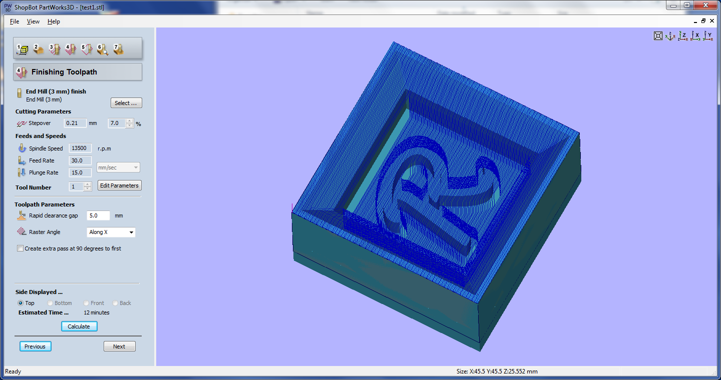
Next I proceeded to do the finish cut of the material and I changed the setting from rough to finish and then started milling. This I understood the algorithm for the finish cut. The machine is trying to smooth the surface by rastering the bit in both X and Y axis. A ball end is recommended as it produces best finish on ball end
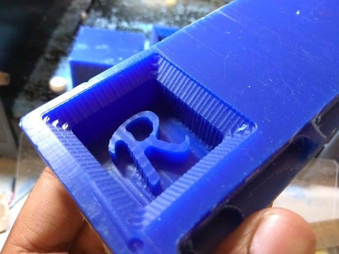
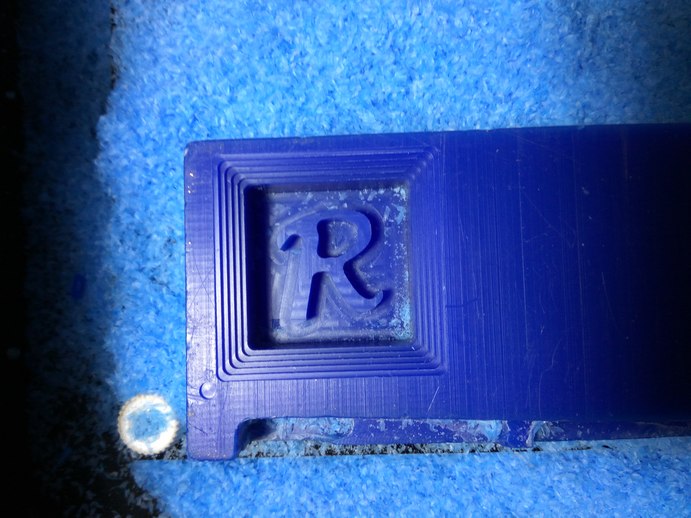
It took about 10 min to the rough cut and an another 12 mins to do the finish cut. the results came out good and if I had used the ball end the edges would have smoothed up a bit more. I will try it next.
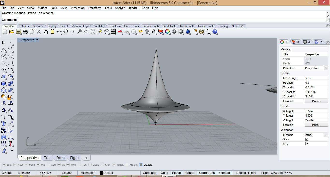
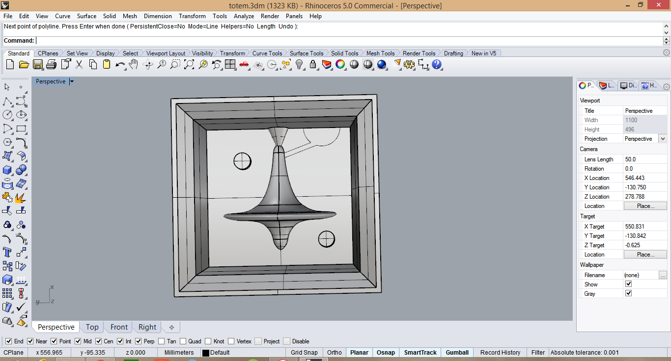
My original plan was to make a totem from the movie inception, since it has curved sides I would need to make a double sided mold. I started designing in Rhino. The CAD design is simple, all it takes is a curve rotated about an axis to generate the solid.
I had changed the design a bit before i started cutting, but I forgot to take the screen shot of it. I proceeded to cut on modella using fab modules.
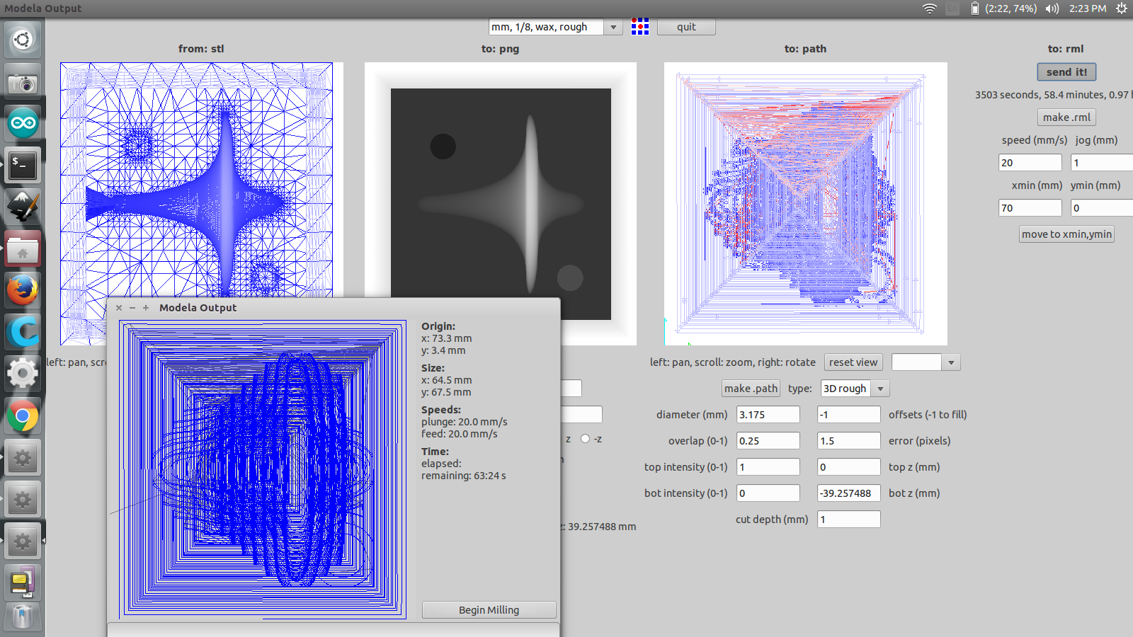
I selected the .stl as inout and the output as our modella MDX 20. The time for the rough cut was around 1.15 hours. I used the 1/16 end mill for the rough cut.
I started the cut and waited for it to finish, but the cut was not successful.
Halfway the machine started behaving erratically and it stopped. I did not understand what had happened. I checked the PC and there was still a lot that needed to be cut. I turned off the machine and tried to resume the cut from the fabmodules. Then the spindle went to the origin and started moving to the X,Y positon I set, but this time, the Z axis started lowering as it was nearing the X,Y positon. The bit plunged into the wax and cut out the side of my mold. It resumed from the previous cut, but the Z value was wrong. Hence I stopped the cut.
The reason I presume the modella might have stopped might be due to the fact that the wax had melted and deposited as a thick layer on the bit. So the machine might have stopped beacuse of overloading.
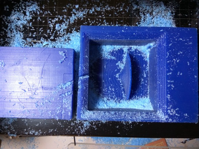
With my recent failure with modella, I took some time to redesign my mold. I was planning on casting it in metal and I realized I had not added any runner or riser to the mold to help with the casting process. Hence I added a gate, a runner, and a riser. What you can see on the image is the previous mold I cut out in wax.
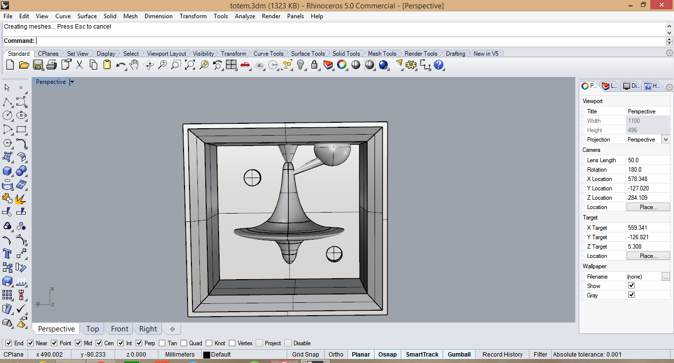
I drew a curve and used the revolve option to create a surface. The big sphere will create the space where I will pour metal.
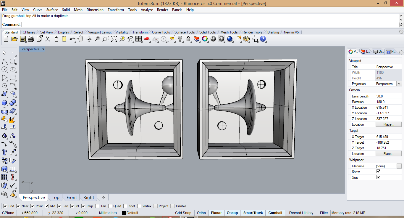
I then mirrored my design on the other part of the mold. to get two halves of the part.
This time I was not going to use modella for cutting the wax. It was misbehaving recently and it is taking a lot of time. Hence considering that other people have to cut out their design, and that I wanted to learn how to use shopbot for 3D cutting. I proceeded to cut my design on Shopbot.
This was the first time I was cutting a 3D file in shopbot and all the settings were new to me. Hence I decided to cut my test part again so that I can learn to use partworks.
The cutting logic is similar to that of fabmodules, The roughing cut will raster cut in the X direction and then the finishing cut will raster in the opposite direction, thereby leaving a good surface finish.
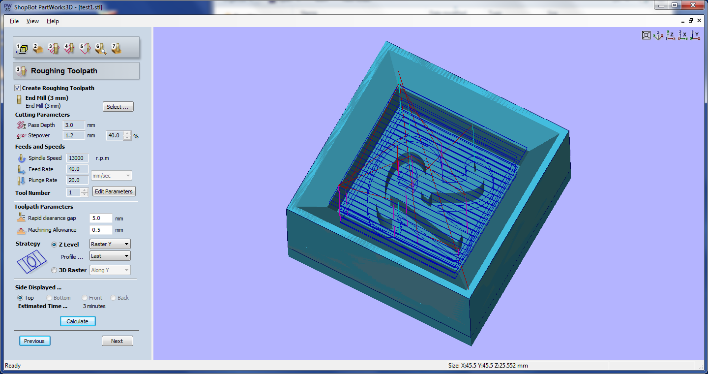
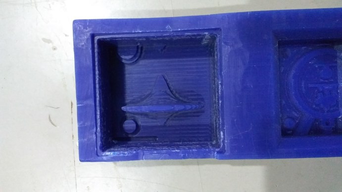
Rough cut takes only 3 mins compareed to 10min with modella. Ofcourse I was cutting at twice the feedrate as in modella. I didn't know how the wax would respond to cutting. I created a new tool for it partworks settings so that I could experiment with the feed, speed and depth of cut.
The finishing cut was done with the same bit as this was a test cut, and I wanted to compare the surface finish with the one cut on modella.
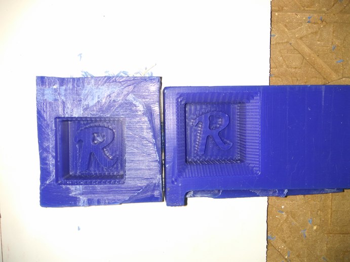
The cuts came out beauifully, since i'm using a 3mm bit for both mdella and shopbot, the results are very similar. But the time taken less than half that of modella's. I'm happy with the result and decided to cut my original design on it.
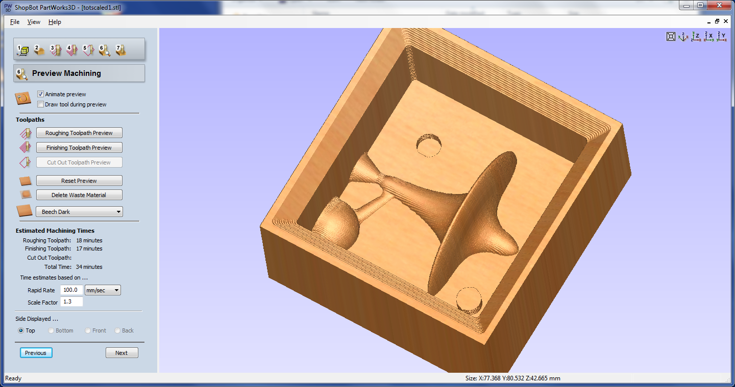
Using the same setting as my test cut, I set up the tool path for my totem in partworks.
During the cut I realized one crucial point, I forgot to check if there was enough depth in the tool to cut the full depth of the model. I paused the machine and checked how far the bit will reach from the spindle, sadly it was not enough.
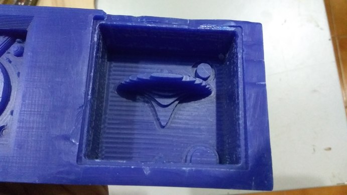
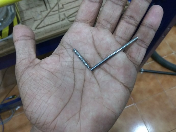
I had realized it too late and my material was wasted. The bit I was using did not have the length to cut 42mm into the material. Hence I went to the inventory and got a longer bit. This bit was specially ordered by some of the students in last years academy. It was the same 3mm bit, but longer. The shank extends to 72mm in length. I thought this would fix my problem.
This is where things went south. I kept thee bit at 45mm from the chuck so that it would give me enough clearance to cut the full depth of the mold. In Neil's lecture and some places I looked online, everyone mentioned that wax is pretty easy to cut through, well I found out that this is not entirely true. The wax was dense but, I knew it was not as dense as plywood, hence I used the same feed rate as when I'm cutting plywood 40mm/s. Only this time one thing had changed. The bit length.
This was the first time I was cutting with a longer bit. I didn't take into consideration the physics of using a longer bit. Basically the farther away you put the bit from the spindle, the more bending torque its going to experience. This tiny detail skipped my mind.
I turned on the spindle and started to cut the wax. In the second pass itself the bit broke. And that too right at the edge of the flute, rendering it completely useless. This was a sad moment. It was a new bit and I didn't even have the time to test it.
This was a major setback. I did not have time to machine in modella, and the normal 3mm bit I was using did not have the length required to cut the model. Hence I decided not to cut it again. The design was too fragile and takes a lot of time to make. I'll use the test pieces I have cut for molding and casting, and when I get time I'll come back and do my original design.
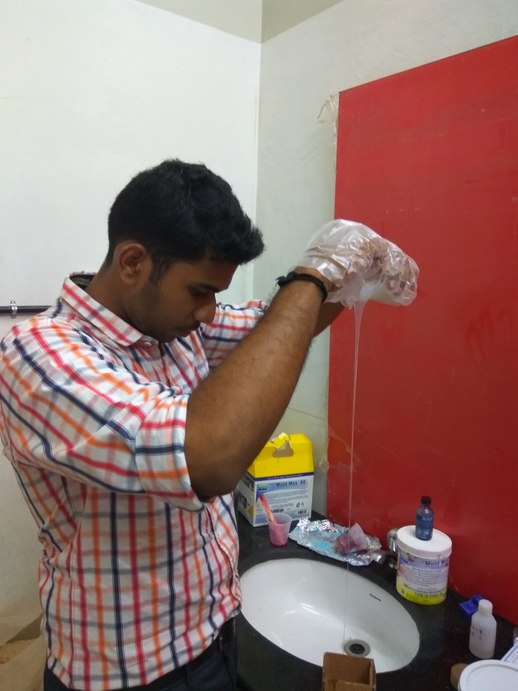
I noticed that there was a lot of wasted wax while cutting and I wanted to try and recast that wax back into machinable format. Hence me and my friend Syed made a square mold from an old box and used mold max 60 as the material for the mold. My instructor told me this was the one which can withstand the heat from the furnace.
i read the datasheet and found that this is not as safe as silicon, It needs a well ventilated place when being mixed and cast.
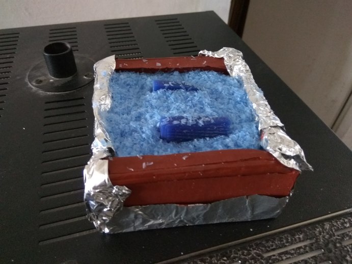
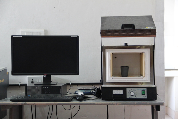
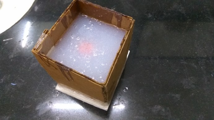
We made the mold and put the left over wax from machining into it along with some broken wax pieces to test if they will melt evenly. I set the furnce to around 250 degrees, the melting point of the wax was around 200 degrees.
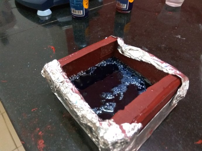
I periodically checked in the furnace the condition of the wax and after a couple of hours it was fully melted.
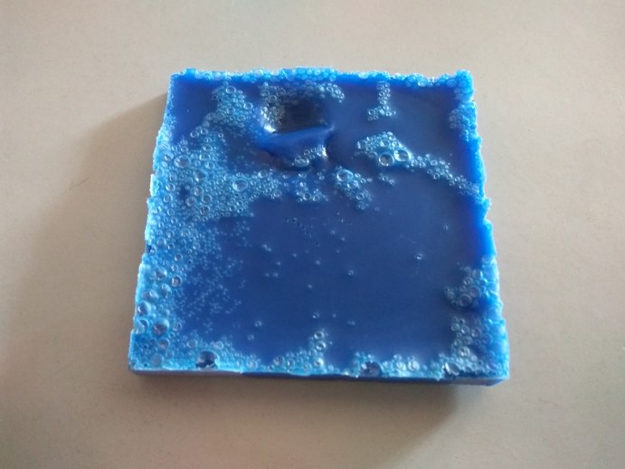
The recast wax was not perfect, it had a lot of air bubbles in it, maybe if I leave it in the furnace for a few more hours the bubble will all rise to the surface. We we could provide vacuum, I guess we will get better results.
For some unknown reason the wax became harder than normal wax. I don't yet understand what happened to it but it was noticeable harder than the uncut wax. More tests need to done to find out the reason for it.
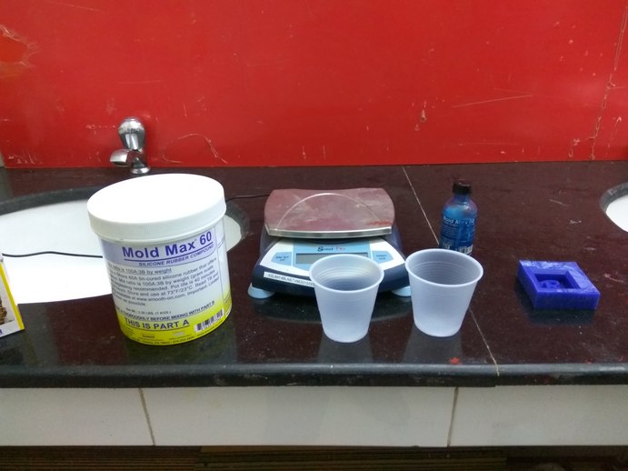
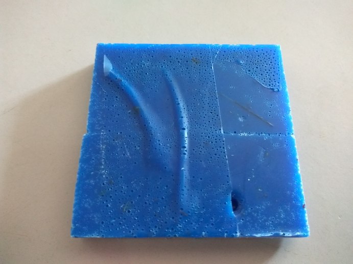
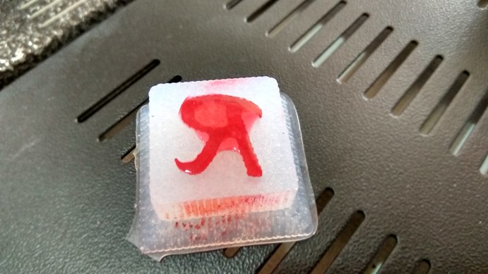
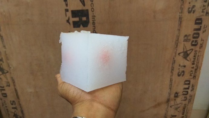
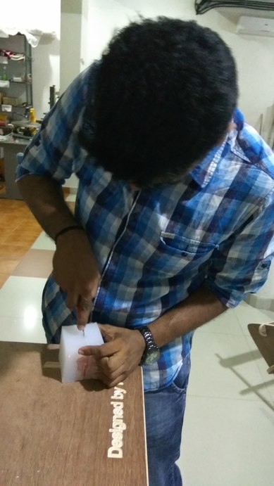
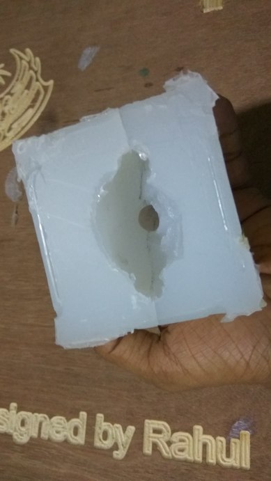
As I was using Mold Max 60 for making the square mold for recasting the wax I also decided to put some of them in one of the test pieces I cut. The material was mixed in the ratio 100:10 and cast into the mold. This wax is very thick.
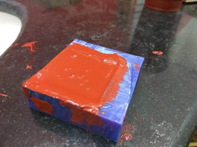
After 24 hours the mold came out well, There was not air bubbles trapped anywhere near the surface of it, the surface finish was good.
I had previously used the heat gun on the wax in hopes of smoothening the surface a bit. Good technique but requires skill to pull it off. That is why you can see the rounded edges on the bottom of the part.
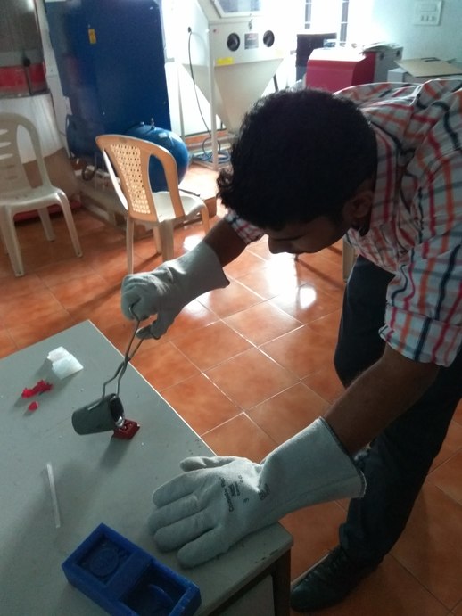
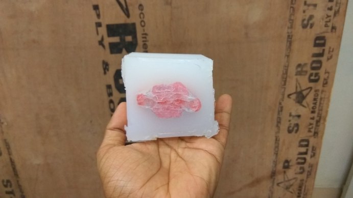
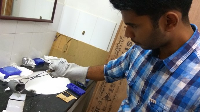
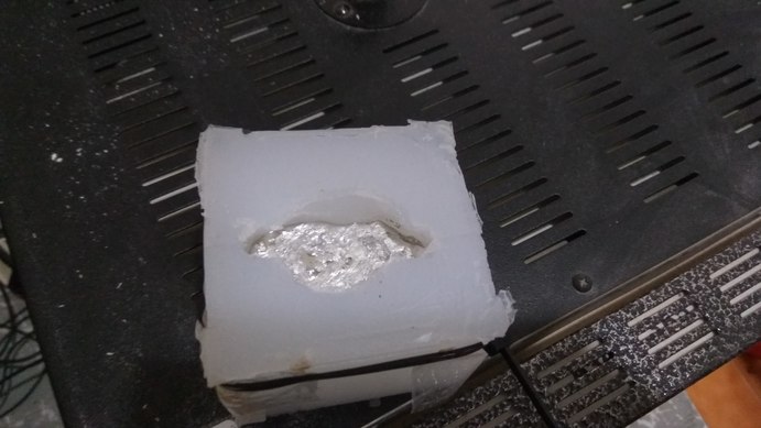
I then proceeded to melt the Babbitt metal in the furnace and pour it in the mold. The metal melts around 300 degrees Celsius, I heard in the lecture Neil mention the temperature of 400 degress will give better fluidity to the metal. Hence I set the temperature to 400 and proceeded to cast the metal in the mold.
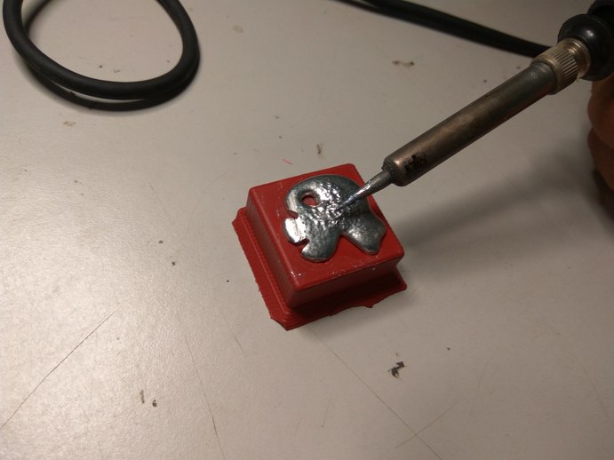
Since this was my first pour I was not that accurate, I poured excess material but I though of a neat way to do post processing of the cast part. Since the metal melts at low temperature I can using a soldering iron to melt the metal and reshape it. I set the iron to around 700 degree Fahrenheit and melt the excess material away.
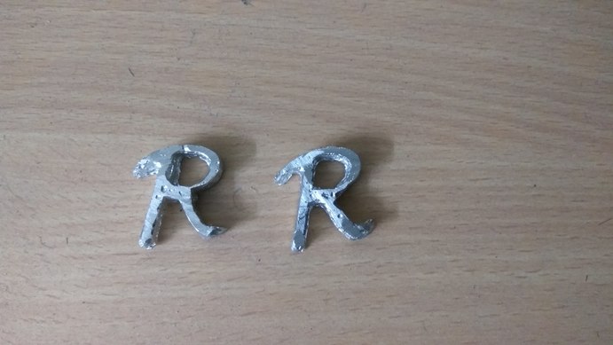
This was the finished cast part after post processing, It came out good and I liked the finish of it, There are still some air holes left on the surface but it needs proper pouring technique to get rid of them.
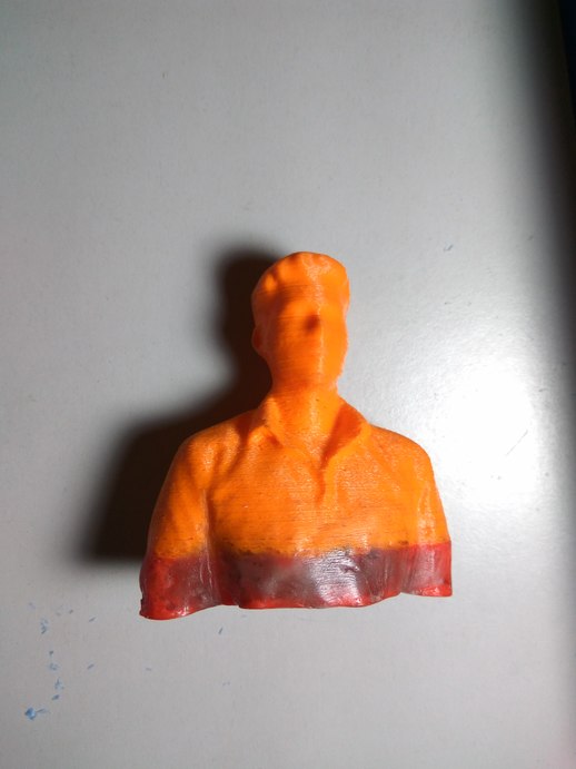
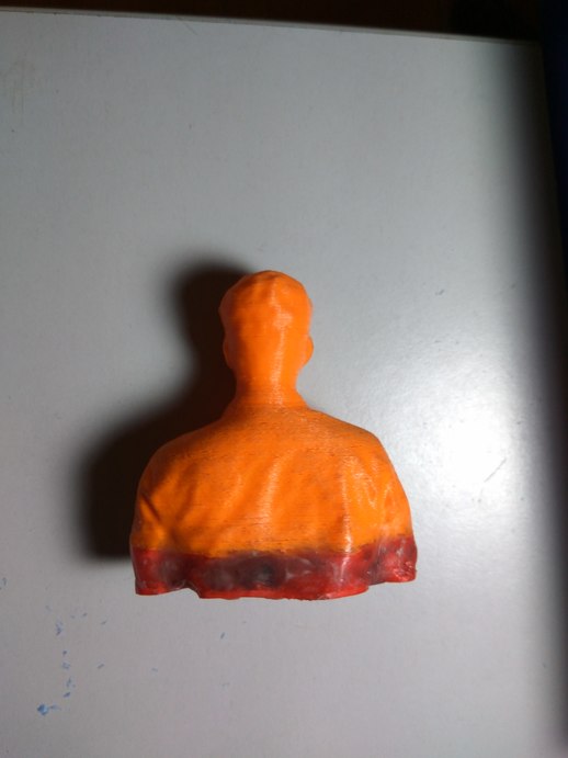
Next I wanted to try and make a mold of myself. I had a 3D printed version of myself I made in the 3D scanning and printing week. There was a slight problem at the bottom of the mold, the print material was not good and the settings were not proper when I printed them, hence midway I switched out the material, thats why the mold is in two colors.
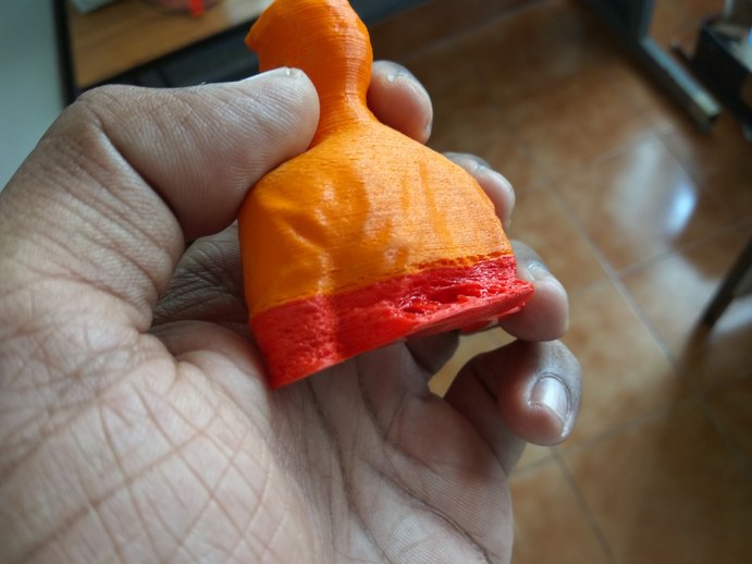
The 3D printed surface is not the best surface for making a mold out of, there are lines which run across the width of the material. Some one told me you can use a heat gun to smoothen the surface of the mold, i was skeptical about it I also wanted to try it, Hence I used a heat gun on the bottom portion of my mold in hopes that I could get a better surface finish. I was wrong, It was a bad idea. Kids, when someone says you can use a heat gun on a 3D printed model, just smile and wave.
The model had warped, shrunk inside and it also tore a hole in the back of it. I made an existing condition worse. There was a small tear in the beginning but now it has become a casam.
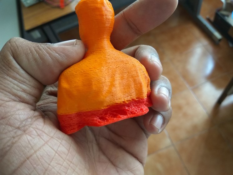
Thankfully I tried it only on the bottom portion. Now I was left with a model that was shrunk at the bottom, this would not make a good mold for casting, Hence I began thinking of ways to fix the problem I had created.
Well as they say, Desperate times calls for desperate measures, I had found an unconventional solution. I will remake the damaged parts of the mold with my hand and some wax.
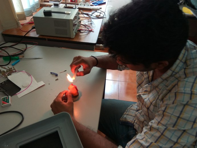
I got some wax candles and started pouring the melted wax into the cavity. This was tricky and It took some time to completely fill the cavity and the bottom portion of the mold.
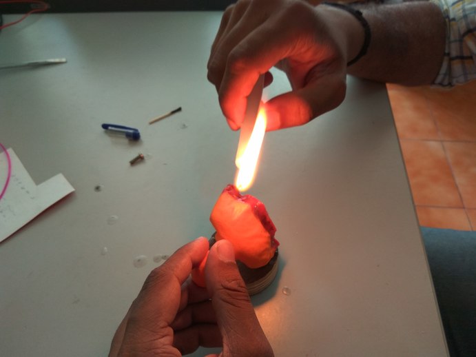
Now comes the hand work. With a small semi-rounded file, I began scrapping away the excess wax. This takes some patience and skill to complete.
Finally I had sort of fixed the problem I created, I restored the original surface of the model. The work of an artisan in the making. I know it doesn't look good visually but the surface is restored and i can make the mold with it.
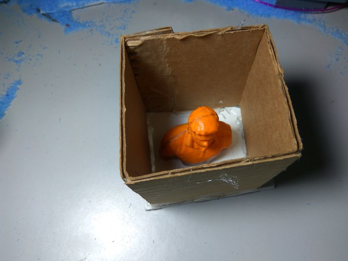
I then had the bright idea of covering most of the surface of the model with wax so that the wax would smoothen some of the wax in the 3D print surface.
I made the mold box from cardboard, which I measured,cut and stuck to the board with hot glue.
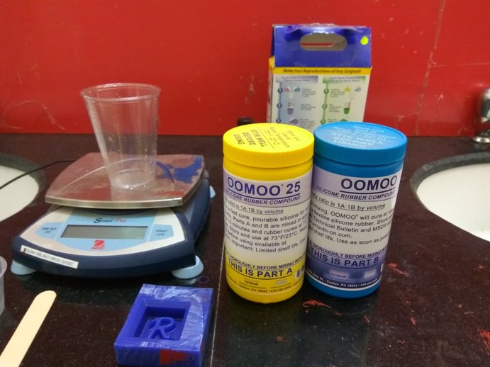
There was lot of oomoo 25 in our labs inventory, our instructors told us to check them out, as they may have expired. We began to test the material.
The silicon rubber is a two part compound which are mixed in equal proportions.
I opened the package and gave it a good stir and took out a dollop of the compound. It had lost its fluidity. The material had expired. I mixed the two parts together and kept it in the cup to see if they will set overnight, but they did not.
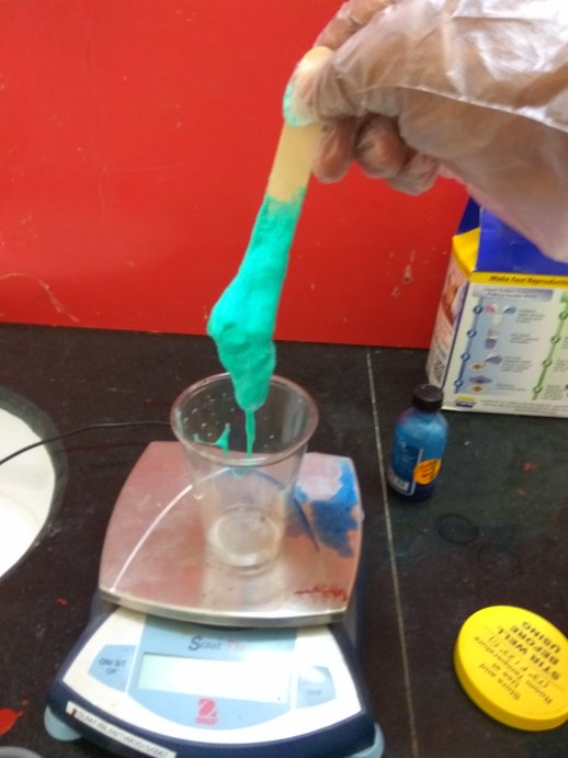
Our next option was a local product, which our lab procured some months back. This is also a two part rubber compound mixed in the ratio 100:10. I measured and mixed the compound so that it will be homogeneous.
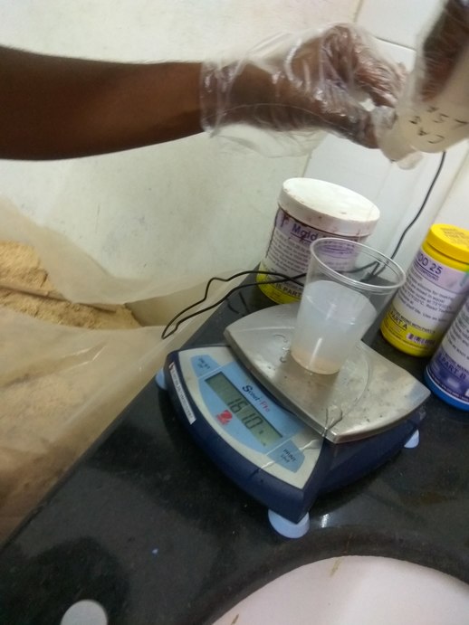
I took a class on molding and casting online from Instructables.com There I learned how to mix the solution and how to not get air into the mold. One technique is to mix the compound gently so that you will not introduce air into the solution and another is when pouring the mold.
In pouring the mold you have to pour from a height of atleast 10 inches on to the lowest part of the mold and let the material rise itself up and fill all the nook and cranny of the part.
What this does is that it will stretch out the material and remove some of the air trapped in the solution. pouring from the bottom up is the best method if your mold has overhangs and undercuts.
The filled mold cavity with the silicon rubber, I set it to cure for 24 hours.
The mold was fully cured the next day. It was very tough.
So my next task is to free the 3D printed part from my mold. I used a blade to cut away the bottom layer covering the part and then cut a slit on one of the side.
The silicon rubber is very tough, Its difficult to cut into, I cut a slit on one side running the height of the model. This way I can free my 3D printed part without fully opening the mold.
Removing the 3D printed part was harder than I imagined, there were some big undercuts.
Now my mold was ready for pouring, I cleaned the inside surface of it ot make sure that there were no debris left inside. I used a Ziptie to securely hold the two halves of the mold, so that they don't open up when I pour the molten metal in them.
I melted a few pieces of the metal in the furnace with the same settings as earlier. Tip: give a temperature slightly higher than the melting point of the metal so that the metal still retains its fluidity when you pour it.
Since this is a big cast, there is a lot of metal inside the mold and it can take some time to cool down. I left it to set for about 15mins and then poured water over to further cool it down to room temperature.
Now its time to open the mold and see how the part came. I felt like a boy opening his Christmas present, I removed the ziptie and pulled open the mold. And there it was, a perfect mini-me.
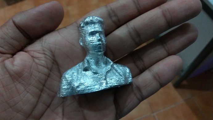
The part looks awesome. All that work paid off. you can see the lines left behind by the 3D mold. But the wax method works, I can see some portions of the cast part has really good surface finish.
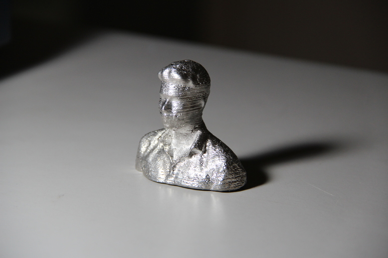
I'm calling him Mini-me, not my evil twin though, but close.
This week has been awesome, As a Mechanical Engineer I have learned a lot about making molds and casting parts, but actually doing it is an unparalleled experience. I look forward to making more molds and casting many parts.
rahulsrajan.com
rahulsrajan01@gmail.com
Trivandrum, Kerala ,
India.

Technopark, Kerala, India