Vinyl Cutting
Vinyl Cutter
I am Over excited to start working off the computers to work with the real world machines ,and also over ambitious to make big things and my creative brain started to pressure up and hanged ,no ideas came so i slowly i started reading the alumini students documentation to understand what is parametric design,then started with the vinyl cutting as it's little easy
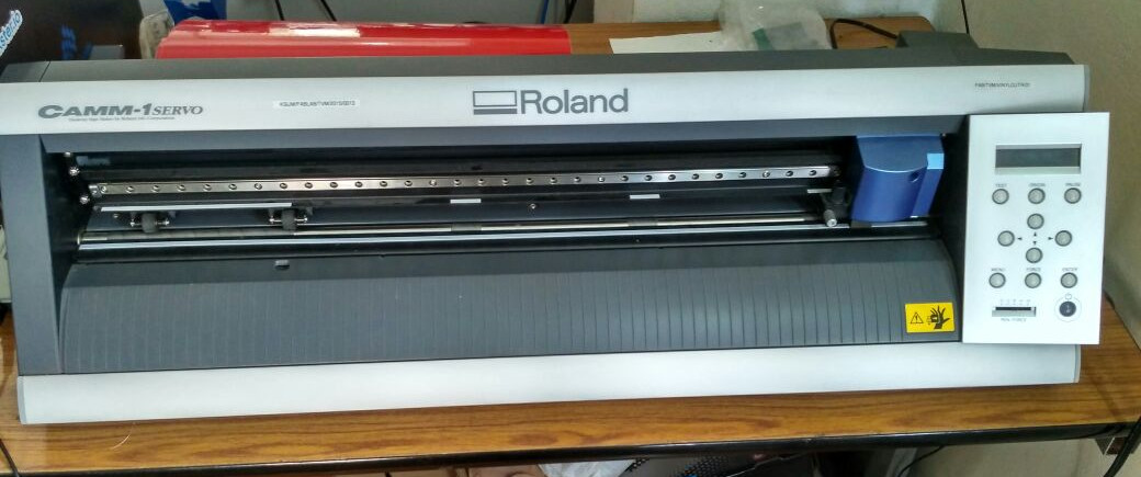
In our lab,we have the Roland desktop vinyl cutter. The knife can rotate on its axis and the bed has rollers for moving the sheet back and forth. The sheet is cut by moving knife over it. We can set the cutting velocity and cutting force depending on the material of the sheet we are cutting.
Setting the Machine
-
First release the pressure plate by pressing the handle on the left side.
-
Load the sheet from the back.
-
Slide the pressure rollers to where the sheet is placed, making sure that the rollers stay inside the white lines.
-
Pull up the pressure plate handle to lock the sheet in place.
-
Turn on the machine, the tool head will move to the home position.
-
Select the type of sheet (Roll or Slice), click enter
-
The machine will automatically move the tool head to the left position of the roller, and give you the width and height of the sheet that is loaded.
-
Move the tool to the desired location using the arrow keys.
-
Press and hold the Origin button to set the origin where you want
process of Cutting on Vinyl Cutter
First you need a .png image file. You can create a file in any vector softwares like Inkscape or even cut a raster image by bit-mapping it. But it should be black and white. Grey scale will not work.
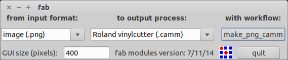
We use the fab module to convert the .png image into the tool path. Go to the fab module and select the input format and the output process and click make_png_camm. A new window will pop up. Now click the load png button and select your image. Now your image will be displayed. You can resize the image to the size you want and click make path. Now you can see the cutting path of the tool.
Default Settings
Diameter(mm) = 0.25 Overlap = 0.5 Offsets = 1 Error(pixels) = 1.5 Intensity = 0.5 Force = 60 Velocity = 5
My Settings
Diameter(mm) = 0.25 Overlap = 0.5 Offsets = 1 Error(pixels) = 1.5 Intensity = 0.5 Force = 90 Velocity = 5
You can leave the rest of the settings as default or edit them depending on the material. For cutting vinyl, I changed the force to 90g and left the rest to defaults. You can also change the cutting velocity depending on the size and intricacy of your design.
Click make .camm button and click send it, now the machine starts cutting.

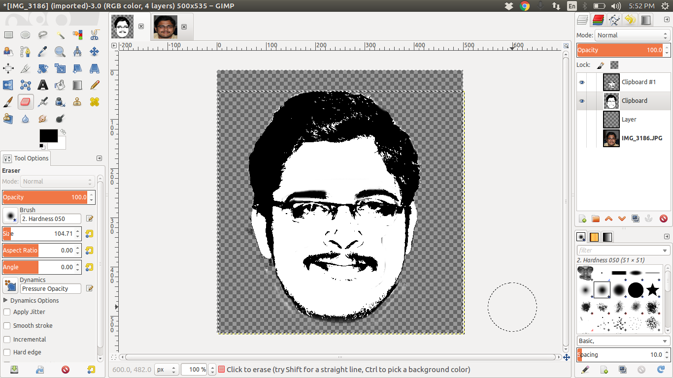
This is my original picture This is my picture after editing to grayscale

i have designed my picture using the GIMP
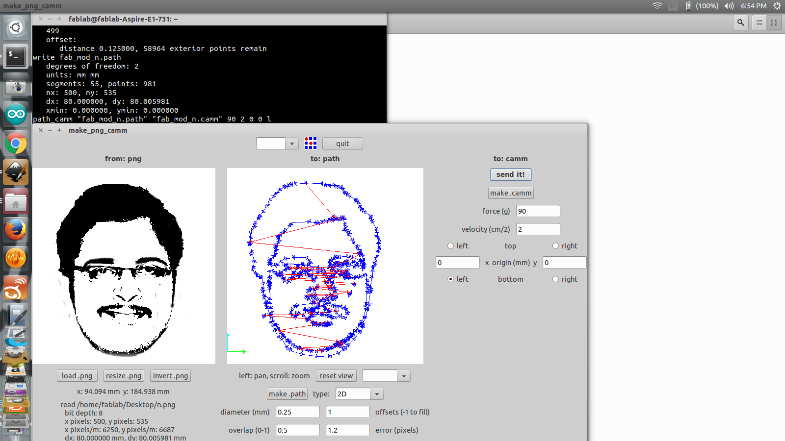
Using fab module for the cutting of the sticker
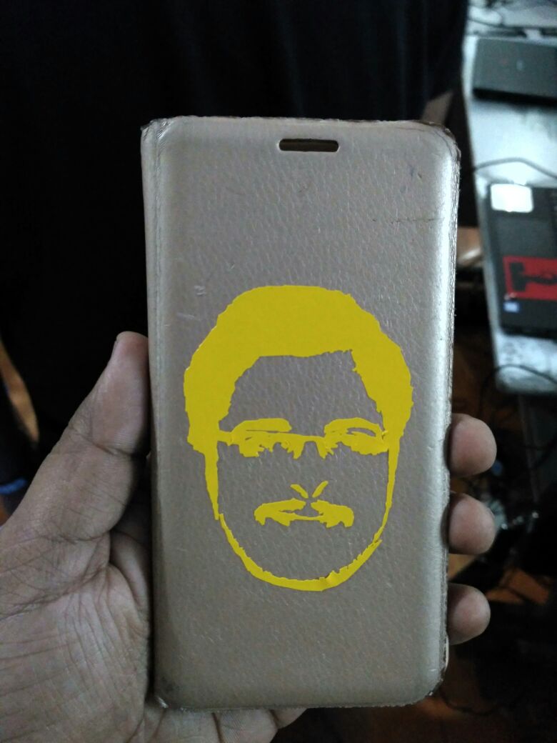
final output of the job
LASER Cutting
LASER Cutter and Engraver
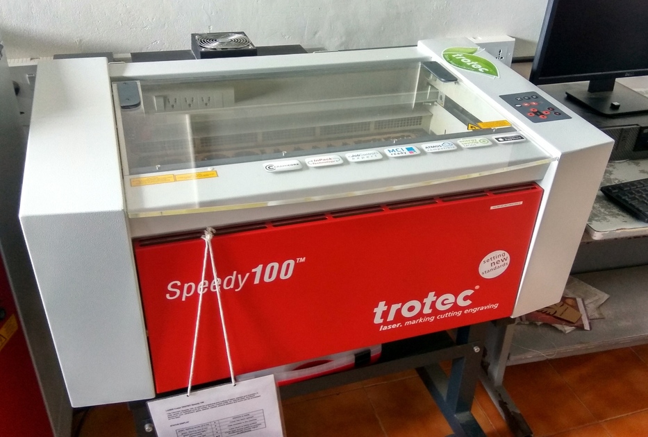
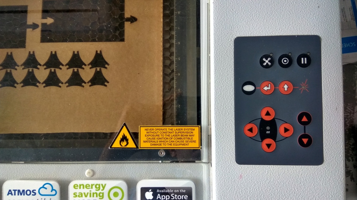
The laser cutter works by focusing a high energy beam of light in a small area to vaporize the material there. In our lab, we use the Trotec speedy 100, it uses a Carbon dioxide(CO2 ) laser for generating the high energy beam. The laser beam is generated at the back of the machine, which is then diverted by a system of prisms. The beam is then focused and moved using a CNC arrangement that allows for rapid 2D motion.
Setting up the machines
-
When you start the machine, the bed moves to the bottom and the cutting head moved to the home position.
-
Load the sheet on the bed.
-
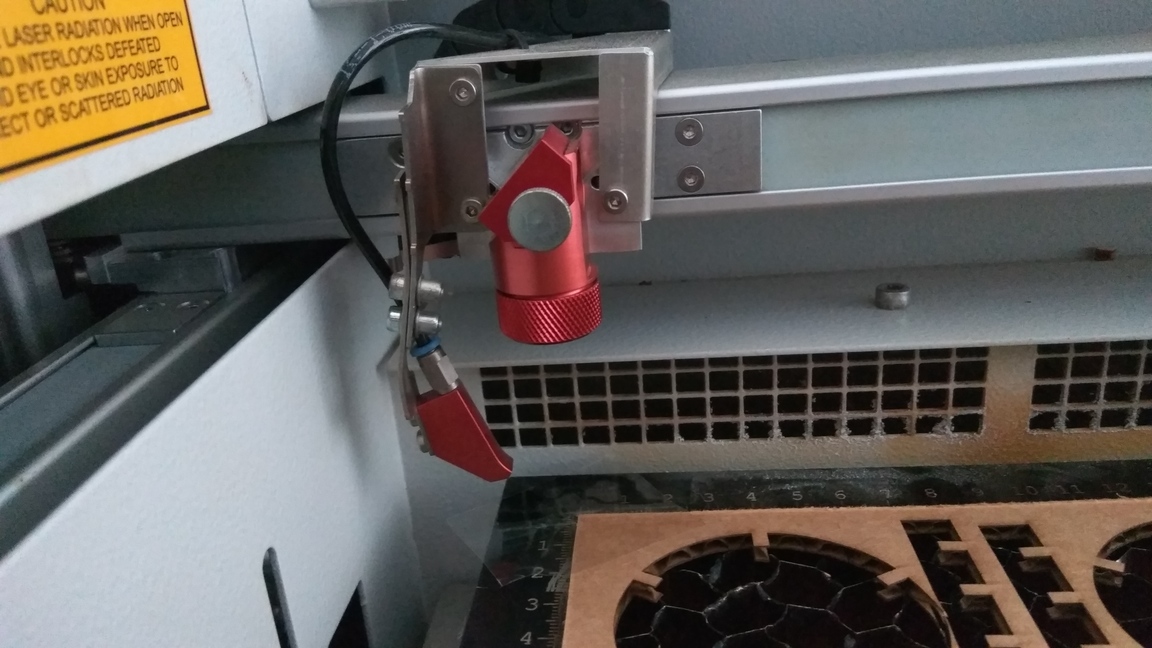
Bring the bed up close to the cutter head.
-
Manually focus the laser by using the spacer provided, hang the spacer on the notch in the cutting head and slowly raise the bed, until the spacer falls off.
-
Set your origin and start cutting.
Cutting logic: How to cut with a laser cutter
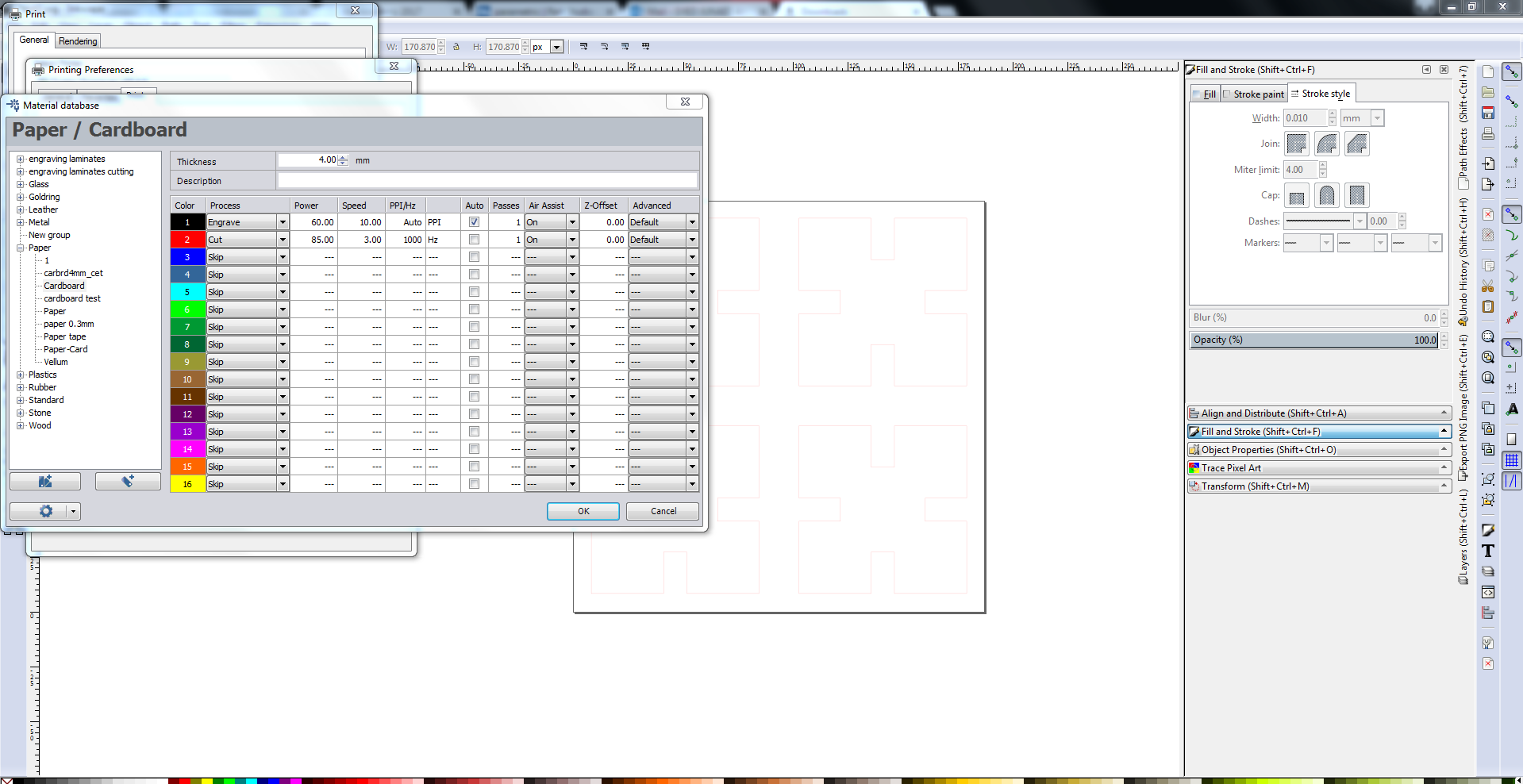
The laser cutter needs vector paths to tell the cutter where to go. It can also etch raster images. You need a vector graphic software like Inkscape to draw the path. The laser cutter works on the basis of colour. Red(R255) means cut and Black means engrave. You can set different colours and give different values of power and speed to get different depths for etching and cutting.
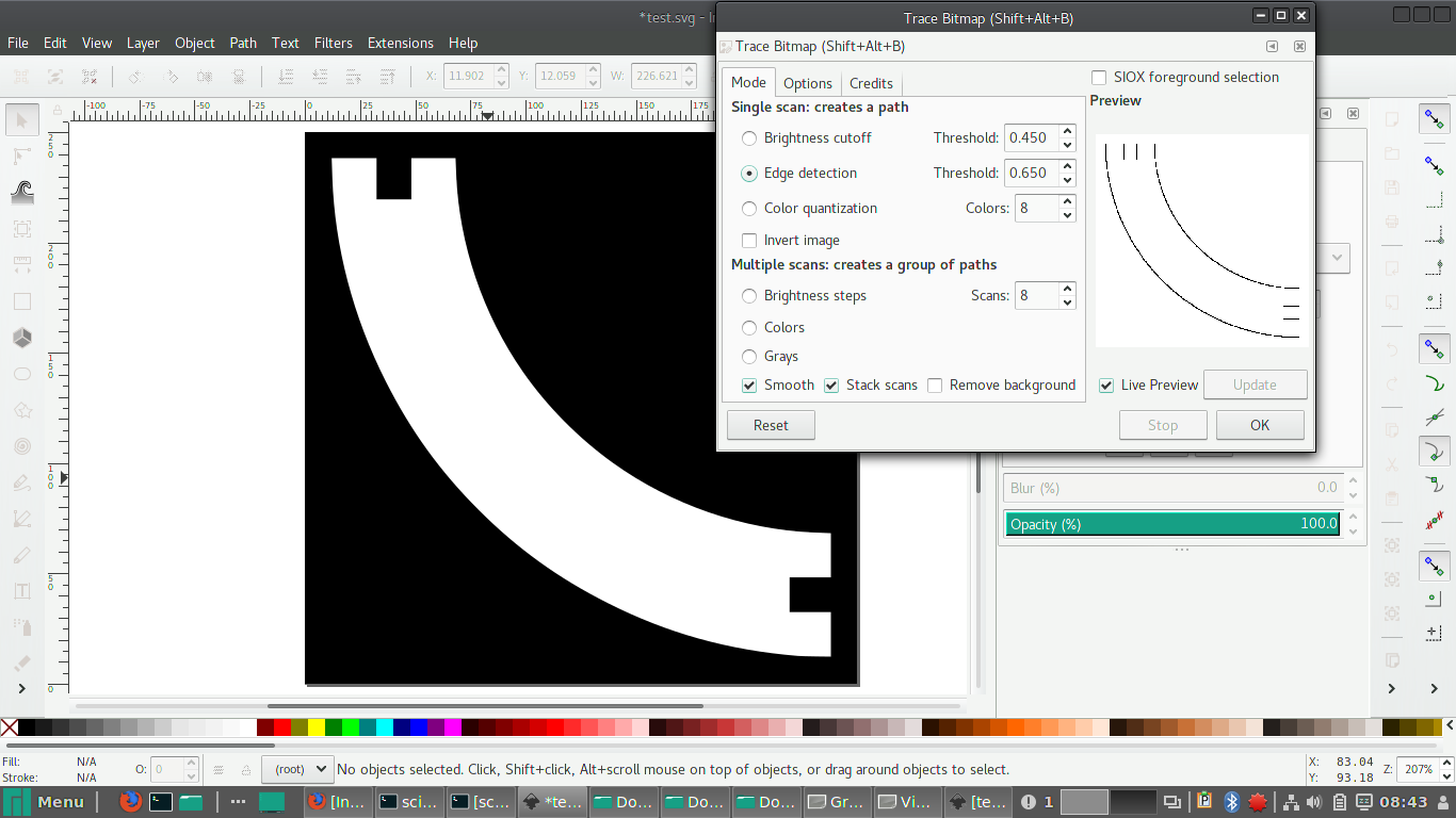
In Inkscape, if you want to engrave an image, then go to Path> Trace bitmap. There are three modes Brightness Cutoff, Edge detection, Colour quantization. Ideally you should try all three modes and see which fits the image.
Once you have the desired vector image, right click and select fill and stroke, and give the colour red to the paths you want to cut and leave the parts you want to be etched as black.
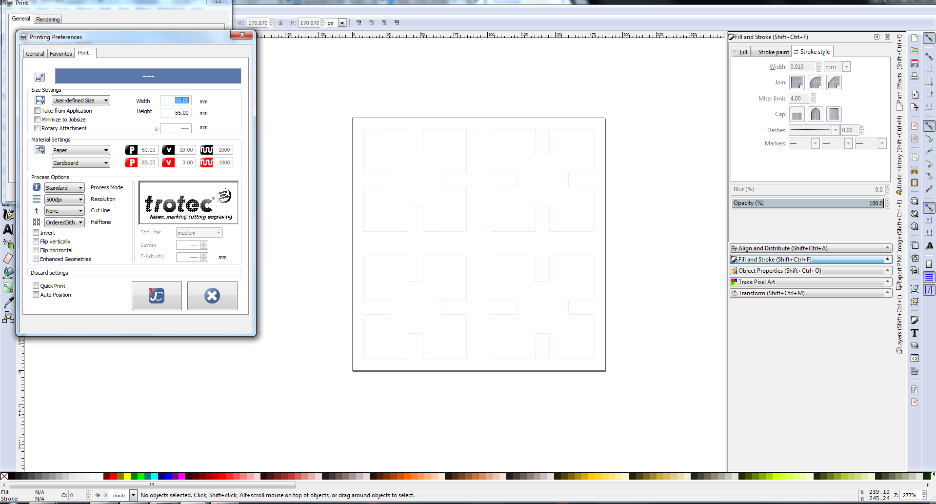
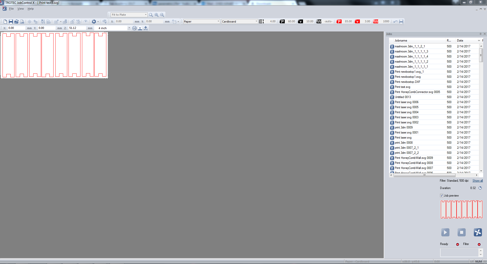
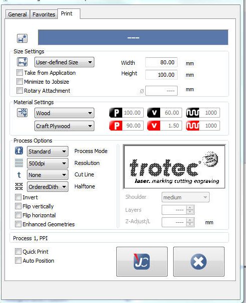
Set the width and height of the image, and set the document properties to close to that of the image you want to engrave. Now click print.
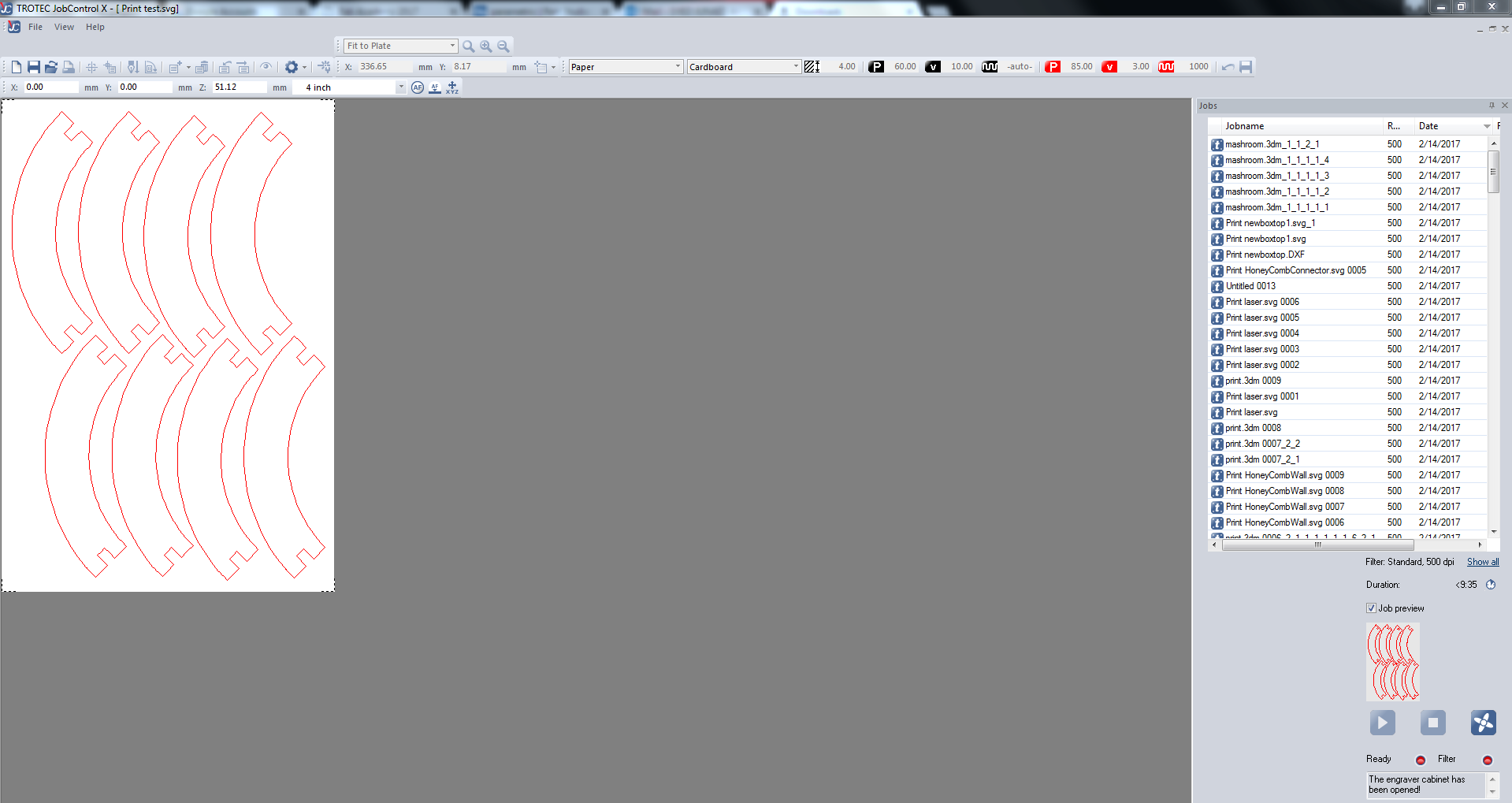
Under preferences, select the type of material and set the width and size of the print document. Done, now click print. The job will be transferred to the job handling driver of the laser cutter. Once you focus the laser and set the origin, click ready to connect with the engraver. Start the air filter and click print.
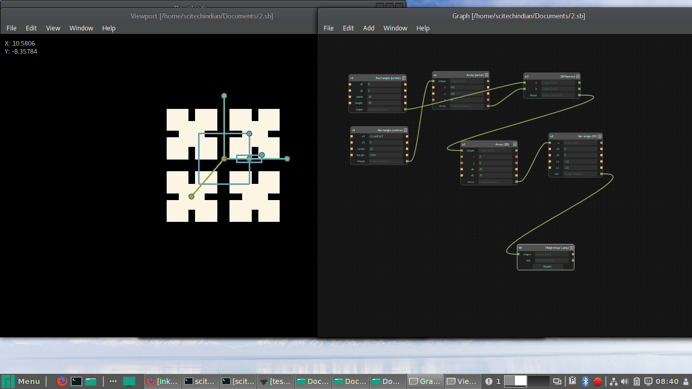
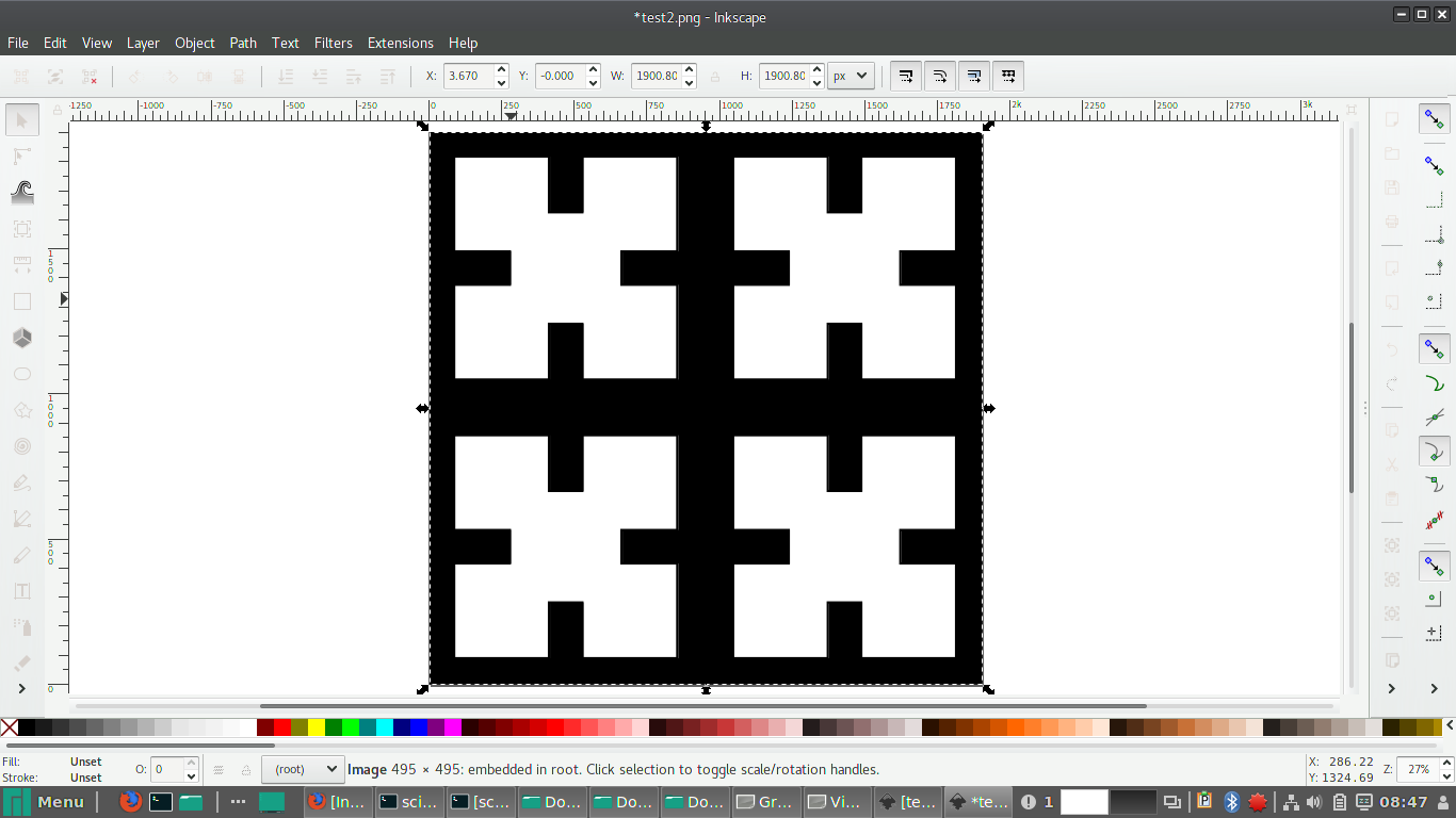
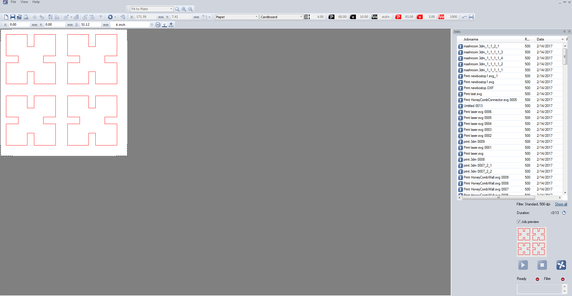
Designing using Antimony and Inkscape
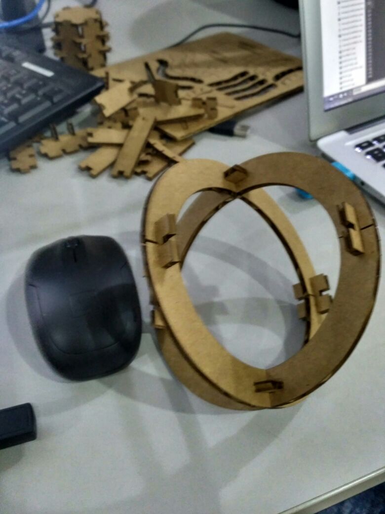
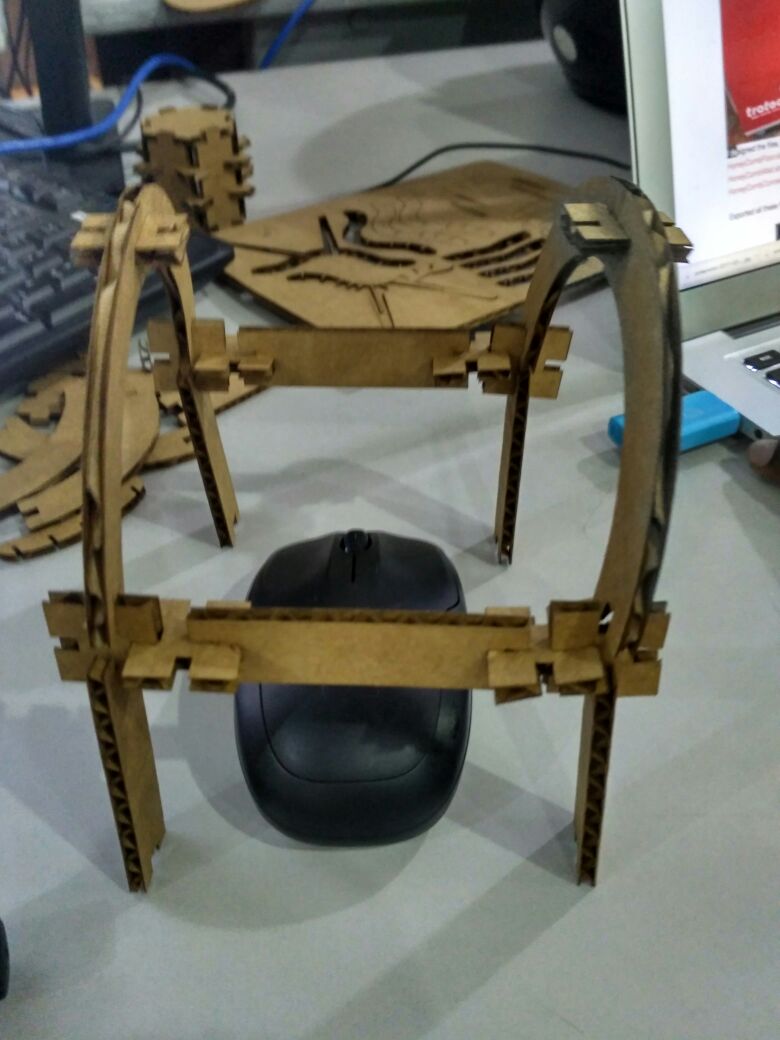
It was great learning time with antimony after long trails of installation and i started peer learning my friend Ganadev helped me to understand the parametric design and i have worked with the multiple nodes like rectangles and circles to build my parametric design of the press-fit kit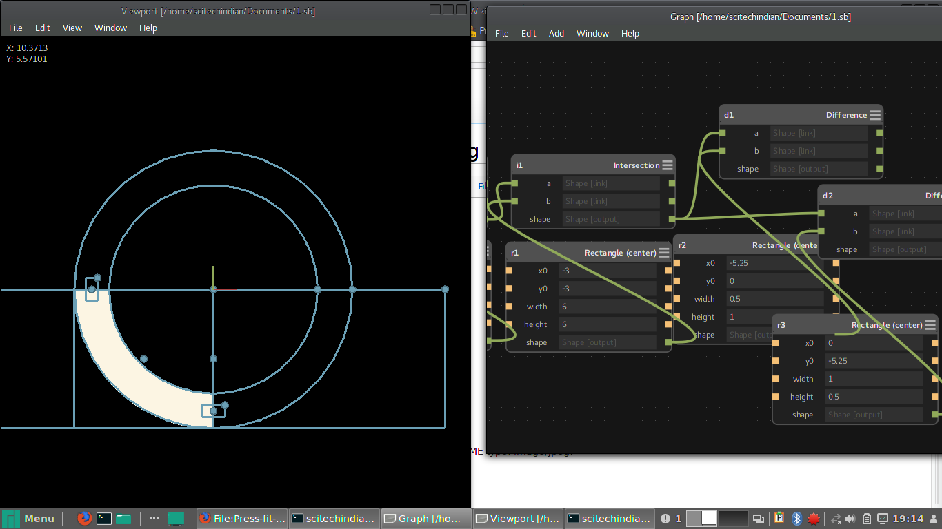
Group Assignment
here we have done the group Assignments
What is Kerf?
The laser burns away a portion of material when it cuts through. This is known as the laser kerf and ranges from 0.08mm – 1mm depending on the material type and other conditional factors.Kerf is determined by material properties and thickness. But other factors also have an impact on how much the laser takes away. The focal length of the lens, pressure of compressed air both have an impact. Kerf widths can vary even on the same material sheet, whether cutting a straight line or a curve line or from laser cutting in the x or Y dimension. The manufacturing tolerance of the material can also impact the kerf.
Finding Kerf
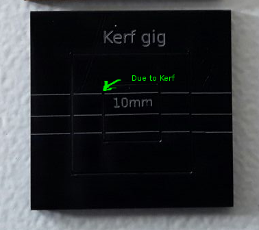
For Finding the Kerf of our machine we have made a kerf gig, which is having a small square of 10mm inner dimension. The Sketch of our gig is showned below, gave some engraving lines for measurement reference
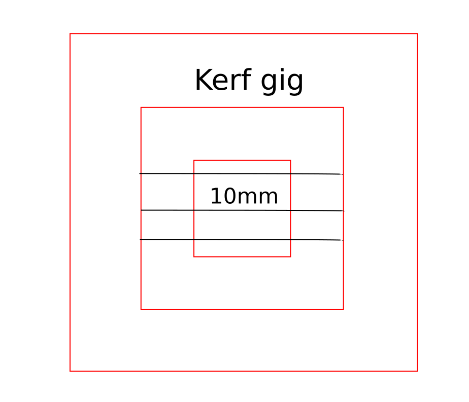
Kerf gig
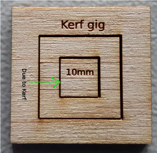
You can see there is a gap in between the cuts, it is due to the kerf of laser. We measured the inner and outer measurements of the gig,inner and outer rectangle dimensions measured,taken the awarage value of the readings and we got the total kerf as 0.65 this accounts the kerf of two sides of the rectangle the actual value of the kerf is half of this value. The calculated value of Kerf is 0.65/2= 0.325mm
Calculated value of kerf for craftwood 3mm is 0.325mm
Next we have done the same thing on acrylic sheet of 3mm thickness and repeated the same measurements and calculated the value of kerf. Here we got the total kerf as 0.488 ans the actual Kerf value is half of the total 0.488/2=0.244mm
Calculated value of kerf for Acrylic 3mm is 0.244mm
Accounting Kerf in our designs
We need to account for the kerf within ourdrawing by adding or subtracting the kerf width from our part dimensions. We have to find out the Kerf for different materials. Once you finalosed the kerf you can use them it into our designs. In our case for designing in craft wood we have measured the thickness of craft wood is around 3.1mm so while desiging we can give 3.1mm-0.325=2.775 instaed 3.1mm. In the case of Acrylic 3mm it is 3mm-0.244=2.756mm. Sometimes the Kerf may vary with material,foucus of laser etc.
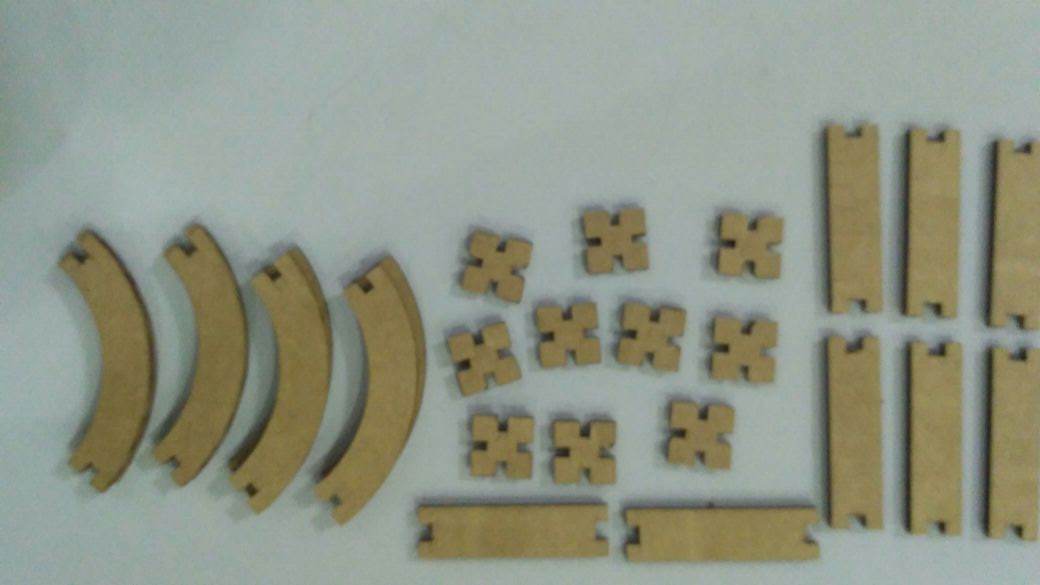
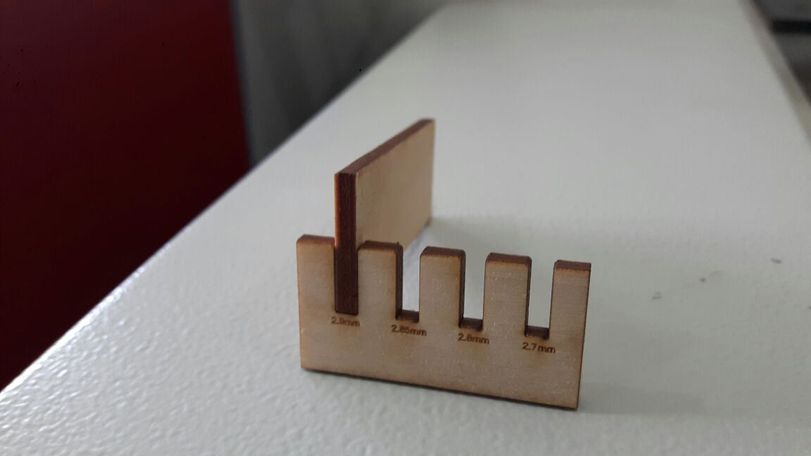
Next we have made a gig for proper kerf for craft plywood. So we made a small gig which is having different dimensionla slots starting from 2.9mm for 3.1mm craft wood and found that the 2.9mm (exact slot value with kerf correction)slot is best for the press fit. The frictional force is normal in this case but the others are having very high frictional force. We can check the force manually placing the mating part ,since we don't have any froce measuring equipments in the lab,we have to go for manual judjment.
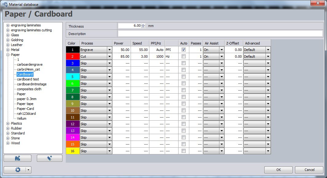
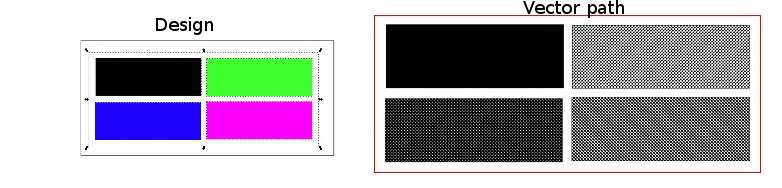
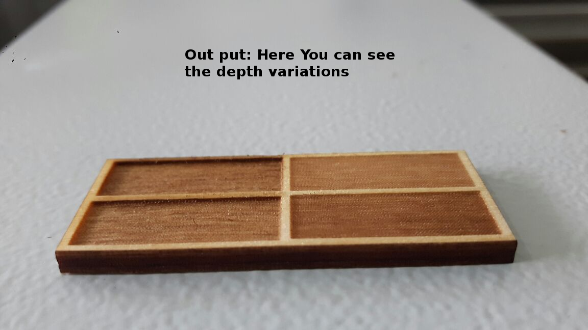
Power Variation Test
We have done a power variation test in craft wood. First we made a plate of different colored rectangles for engraving and we have set the power for each different values starting from black color power as 80,Power 60 to Blue color, Power 40 to Green and Power 20 to Violet. The plate is processed and we got different engraving depths in each as expected.
Group Selfi