Week 16
Interface and Application Programming
Objectives
Learnign Outcomes
Have I ...
Documentation
As part of my final project I am going to use LED RGB, so this is a great opportunity to interact with them and testing colors. I am going to use led rgb COMMON ANODE available on fab inventory and design a GUI, which is a color palette. Where the mouse cursor marks on any part of the color palette the RGB LED will indicate the same color.
Looking for tools to develop this assignment, I had two options, which I had worked time ago, LabView or Processing to made the GUI. I choose Arduino as the protocol to interact with an output, LED RGB as I mentioned.
Processing

I forget it, I had problem during the installation of processing on ubuntu (on windows there were not any problem). After an intensive search, this link could solve my problem, it was very helpful .
I have chosen Processing, to remember the language I resorted to tutorials and examples of Processing webpage, totally recommended. On those examples I understand each line of code, and looking for something that can help me in my assignment.
To understand how serial communication works, electronics tutorials and serial reference are perfect tools! I had a little problem with the port number, because I suposse port 0 is by default, but was necessary to change according your pc or laptop recognize. At the time I test processing, the port were 32 as can be seen in the next photo.
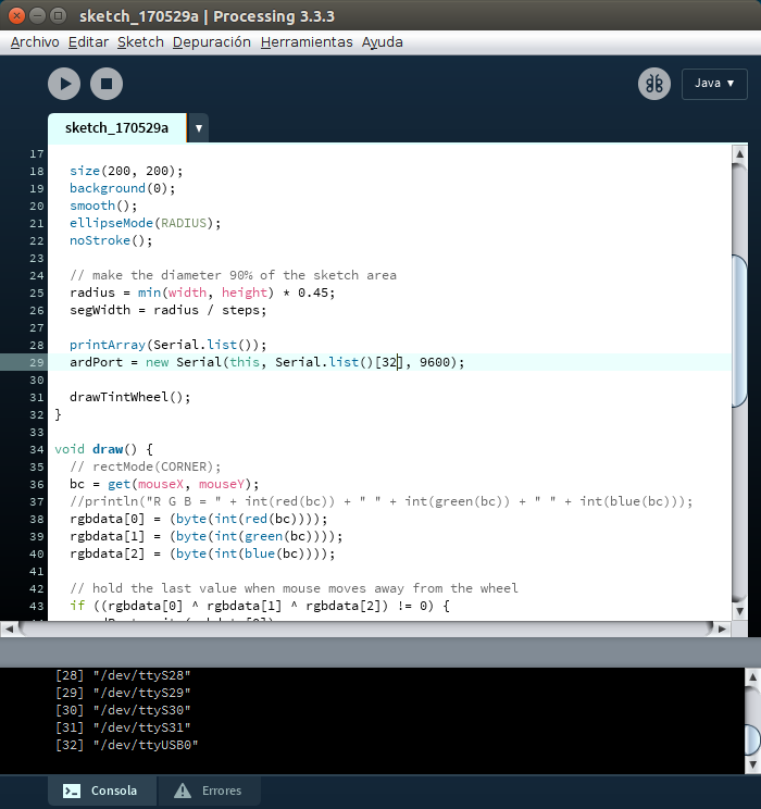
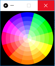
Inside my code, I did a circle wich is the color palette. It has 12 divisions, on the center it resembles white color and differents color around. When the cursor pass over the palette returns three values for R: red G: green V: value in a range of 0 to 255. Those values are saved on an array to be sent to Arduino via serial communication.
Arduino Code
I did not have too many problems with Arduino code. The only drawback was the value I had to send by pins R, G or B, because I was using COMMON ANODE led RGB. For example, if I want to have white color on COMMON CATHODE led rgb, energize pin R,G and B with VDC positive (5V or 255 in case of PWM pin of arduino). For red color, R:5V; G:GND; B:GND (GND or 0 in case of PWM pin of arduino).
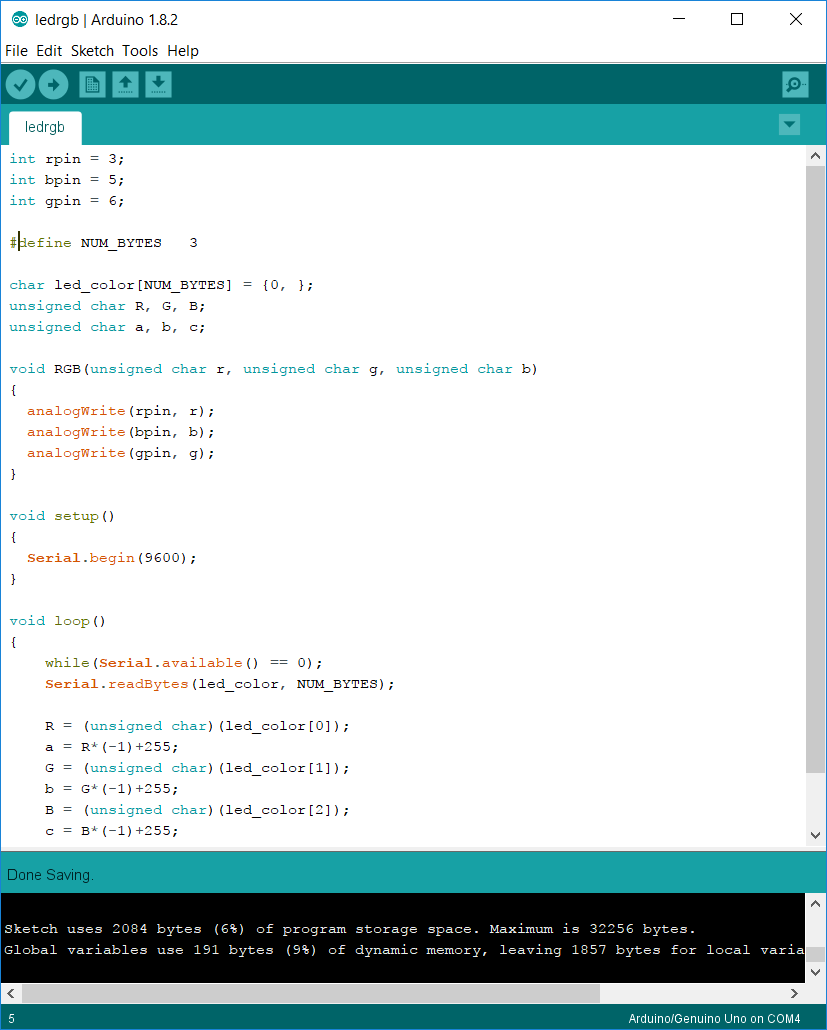
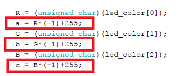
In my case it is the opposite because I was using COMMON ANODE as I mentioned before. For this I did like a negation inside my code of arduino. Because, Processing sends me data for a common cathode led rgb.
After that, I connect my Jhonduino to upload my code using my FabISP and FTDI cable.
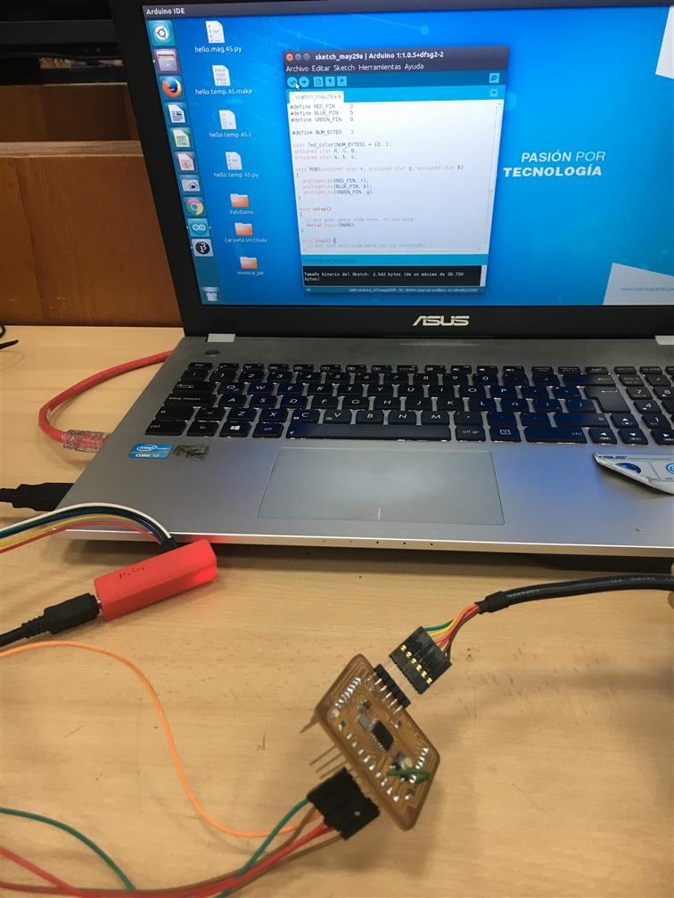
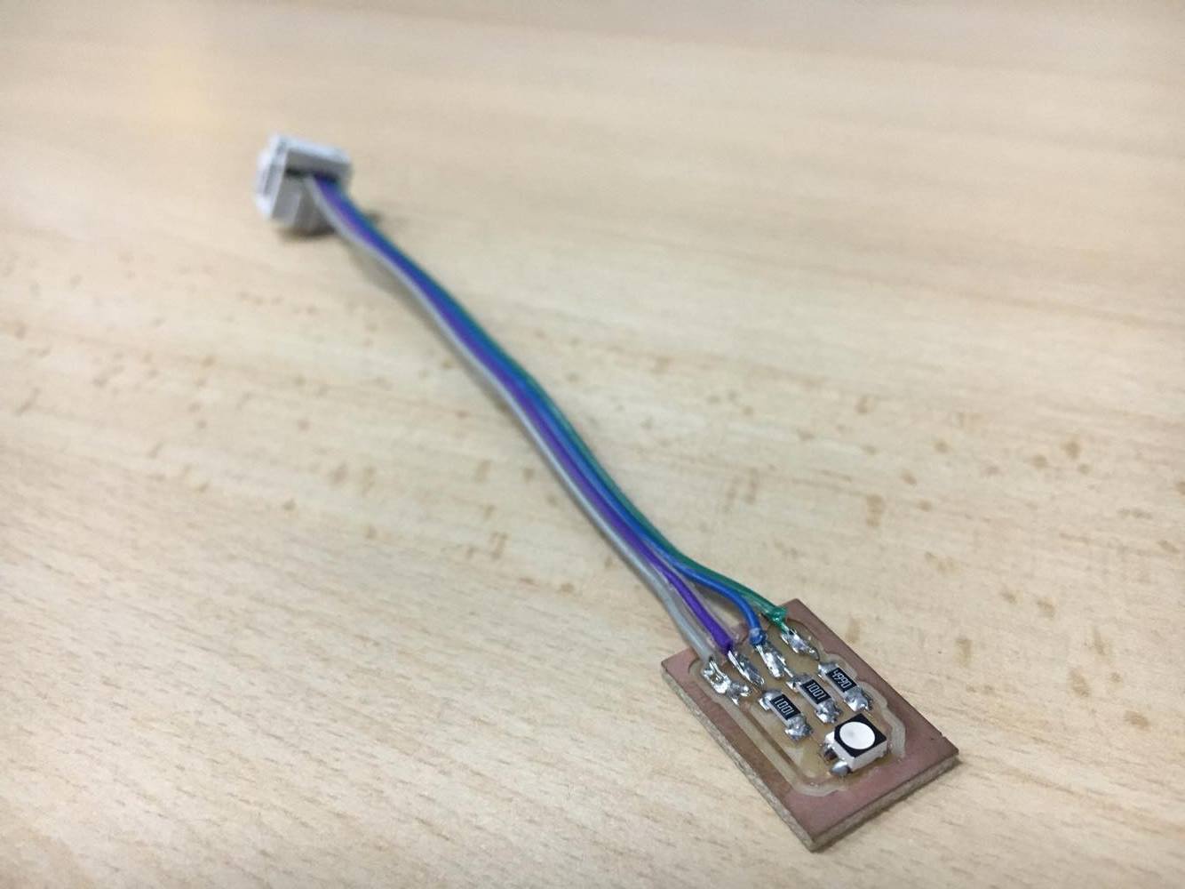
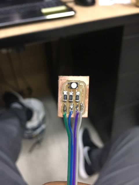
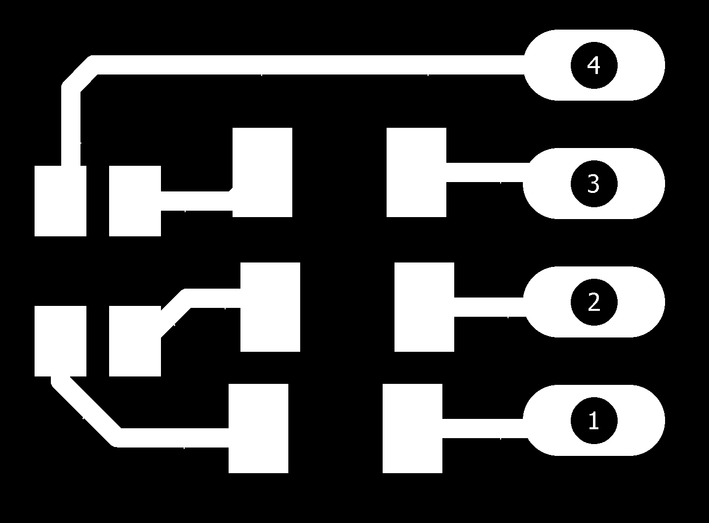
Electronic hardware
In this case I design a simple board using: -1x LED RGB -2x 1kΩ resistor -1x 499Ω resistor -cables and conector(depends on user)
Files
Here my files: - Arduino and Processing code (.rar)
Result
Here is the result of this asignment summarized on a video, do not lose sight of mouse cursor, enjoy it!