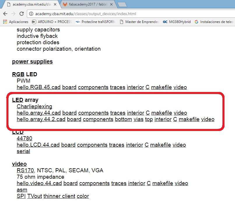
As you can see there are many ways to work with output devices, I chose ARRAY LED, which has 20 LEDs working with 5 resistance of 499 ohm.
STEP 2: DESIGN OF CARD LED ARRAY
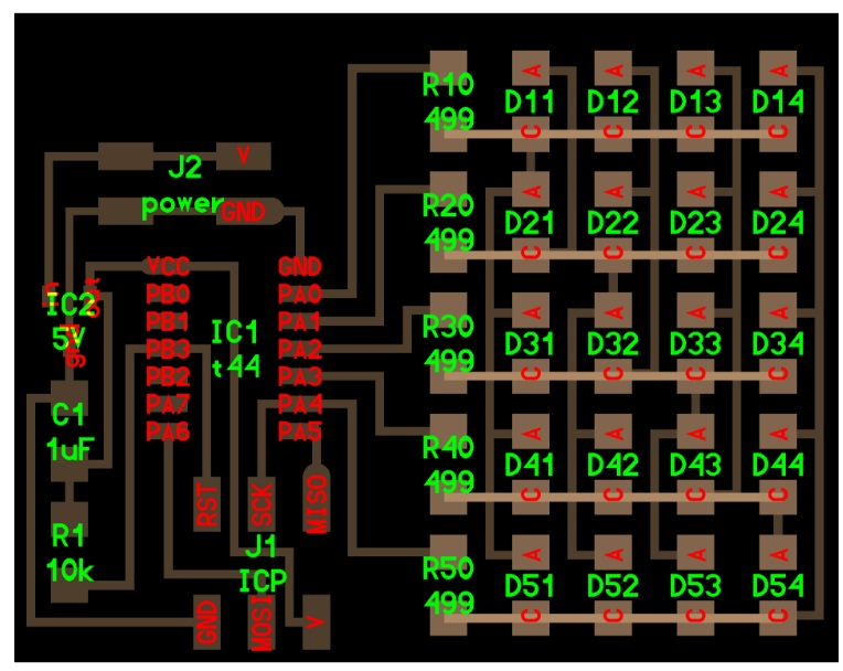
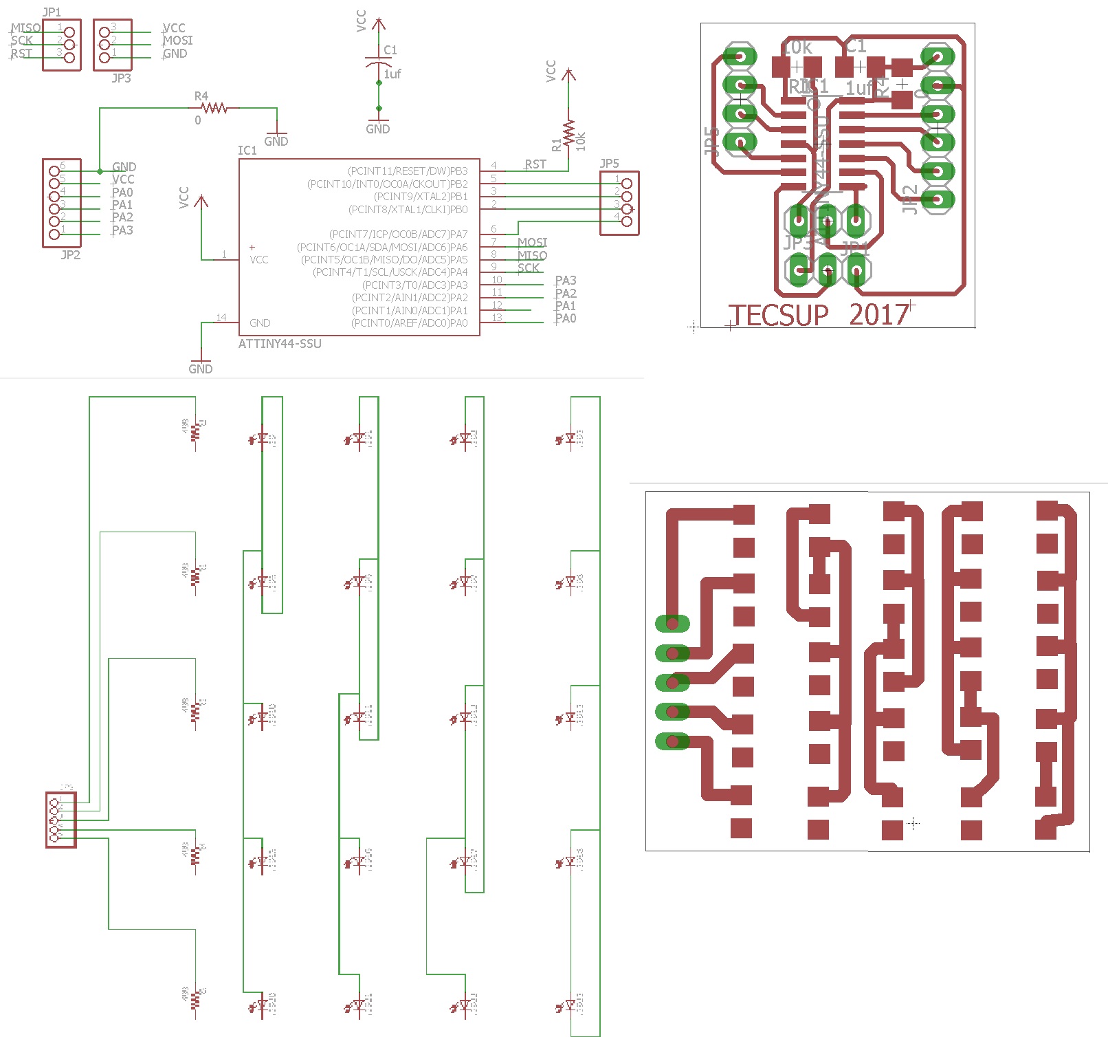
I chose the LED ARRAY project, as shown in the figure. The project was designed in EAGLE. The controller and the array of LEDs were developed separately.
STEP 3: CONSTRUCTION AND WELD IN CARD LED ARRAY
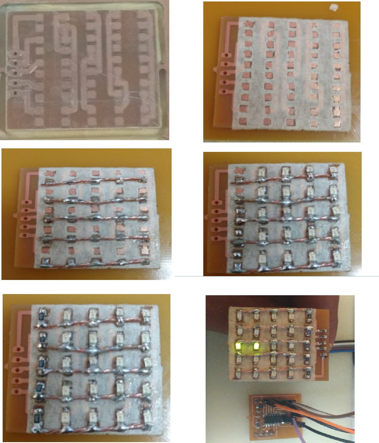
The construction of the card was developed in the LPKF S63, the material is bakelite PCB FR4. Component soldering was done by first covering the board with adhesive tape, then soldering the cathodes of the LED diodes and finally the resistance of 499 ohm.
1.- The E-card is made for the LEDs.
2.- The E-Card is manufactured for the controller Attiny44.
3.- Proceed to protect the tracks with adhesive tape and leave spaces for the common points that are to be joined.
4.- The common points are united with a copper filament 5cm.
6.- Observe the polarity of the diode at all times.
STEP 4: LOADING THE PROGRAMMING ATTYNI 44
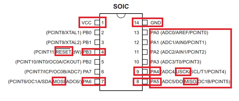
The datasheet of the Attiny44 helped me to identify the pins of port A (A0 - A4) that soon needed to indicate the programming. In addition to identifying the ISP programming pins (MISO-MOSI-SCK-RESET-VCC-GND).
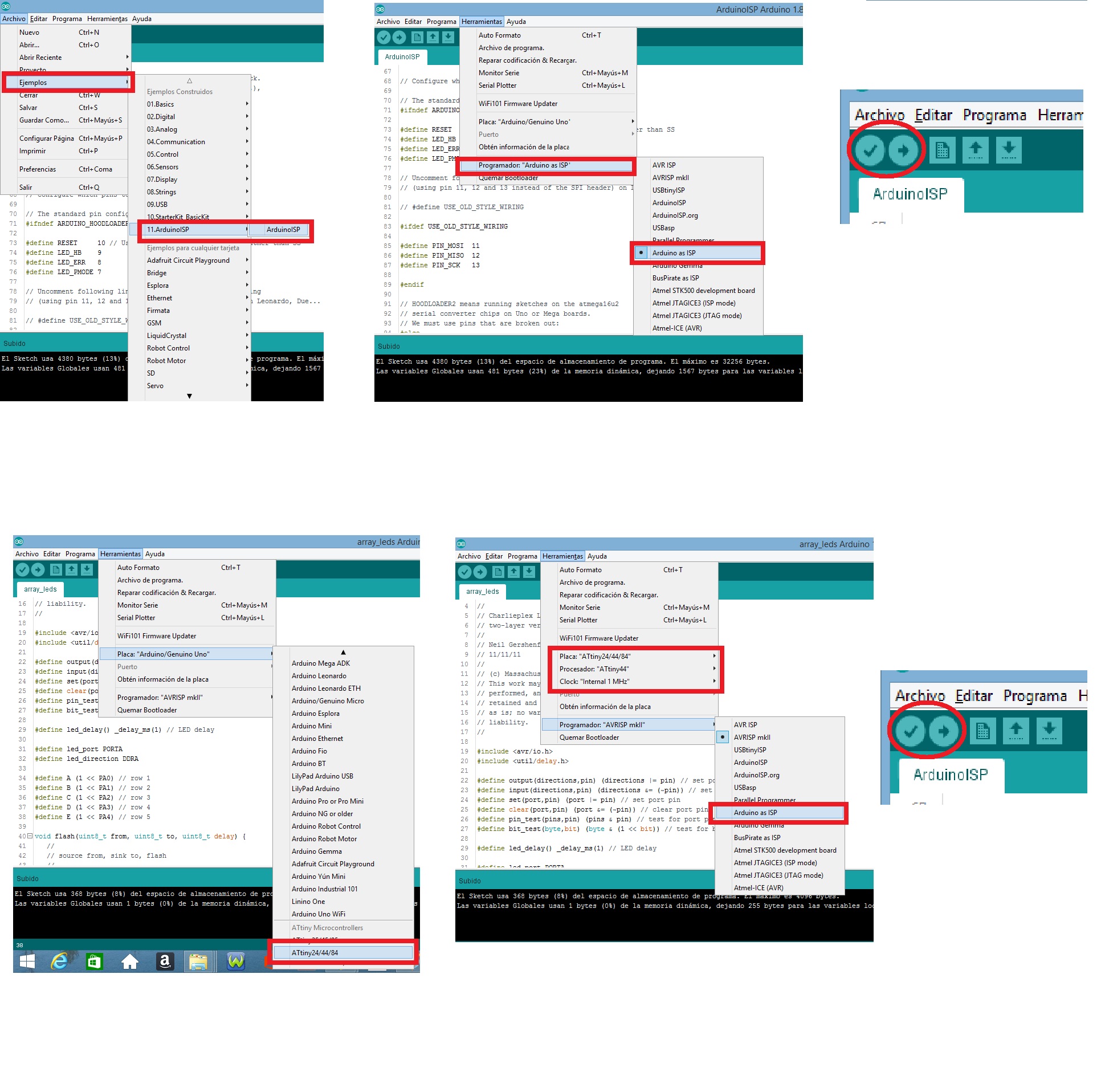
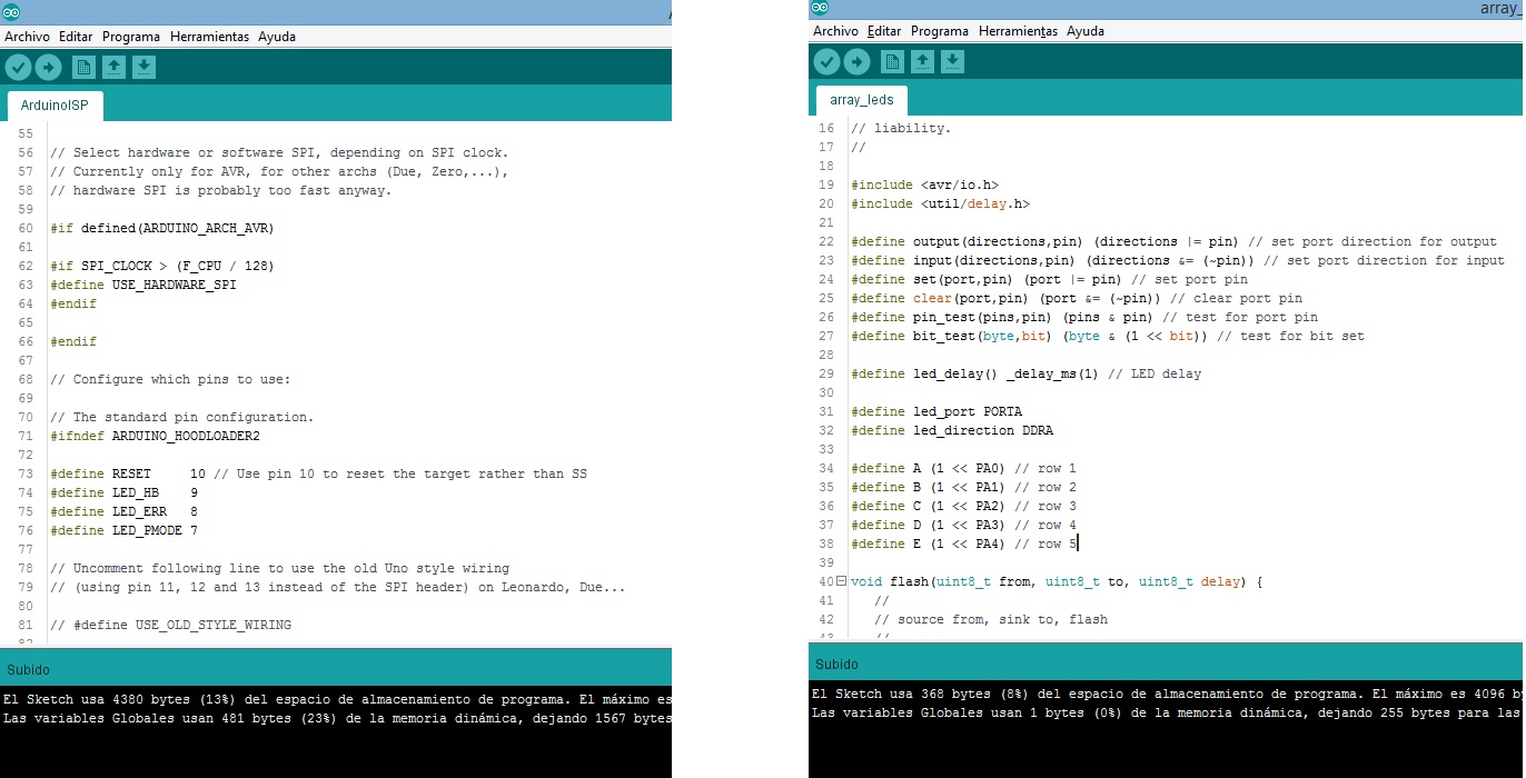
Programming was done in C language using Arduino IDE, as shown in the
STEP 5: CHECKING THE OPERATION OF THE APPLICATION
Once finished loading the program into the Attiny44, I run the program. As shown in the video.