


-Design and mill an electronic board
-Solder the electronic components
-Program the board
-Show the interaction
1 Locate the Fab Academy page (http://fabacademy.org/)
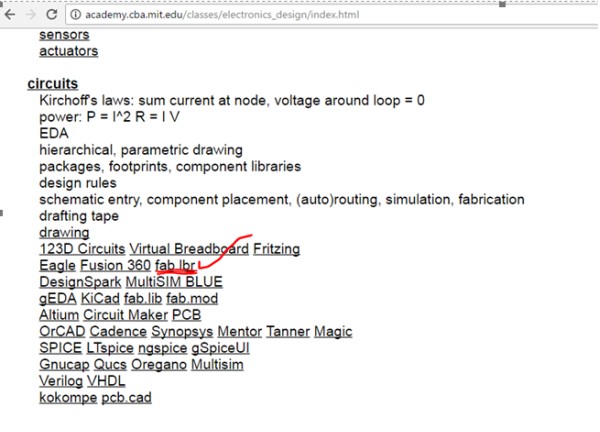
2 Select CLASS ARCHIVE -> 2017-> SCHEDULE-> ELECTRONICS_DESIGN
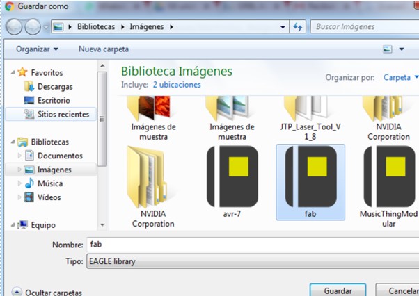
3 Download and save the library to a folder.
4 Activate the Eagle program and then add the library.
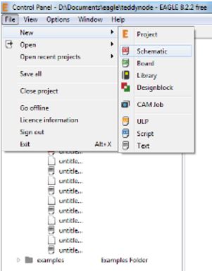
5 I opened a new schematic
6 Then select the ADD option and opened a new Window where we can upload the FAB.lbr library in Manage Lbraries.
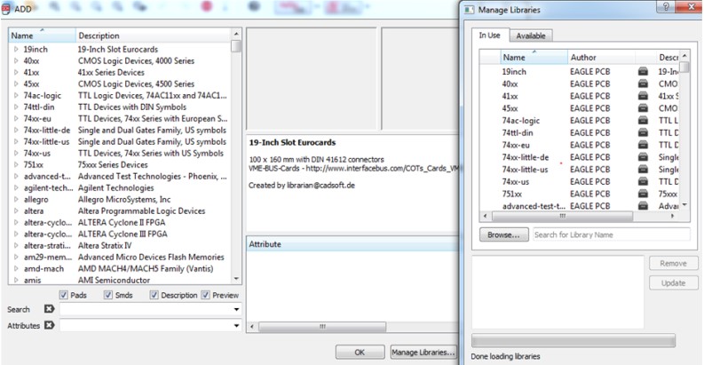
7 Then at the end I could use the components of the library of the Fab Academy
1 Run the Eagle Design program
2 Create a new schematic
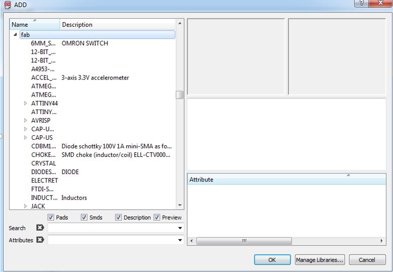
3 Look for the "Fab" library and select the following files
V_REG_MIC2920
ATMEGA48 / 88/168-AU (ATMEGA48 / 88/168)
JACK-PLUG1 (JACK-PLUG)
6MM_SWITCH6MM_SWITCH (6MM_SWITCH)
LED1206 (LED)
AVRISPSMD (AVRISP)
PINHD-1X6
PINHD-1X4
CRYSTALHC49S (CRYSTAL)
RESISTOR1206 (RESISTOR)
C-US025-024X044 (C-US)
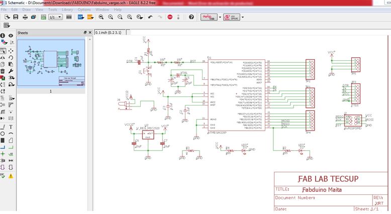
4 Make the component connections in the schematic plane.
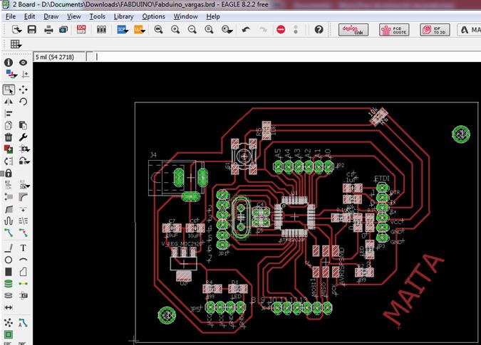
5 Generate a Board to be able to order the components and design our Fabduino board.
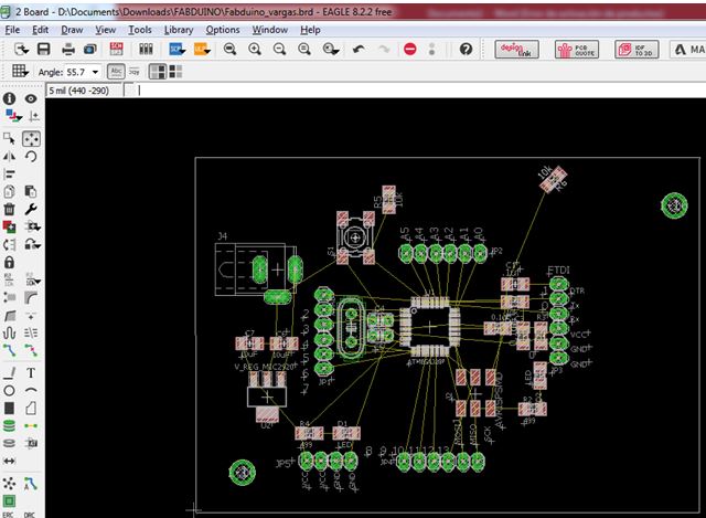
6 Ordered the components so I could perform the routing of the paths.
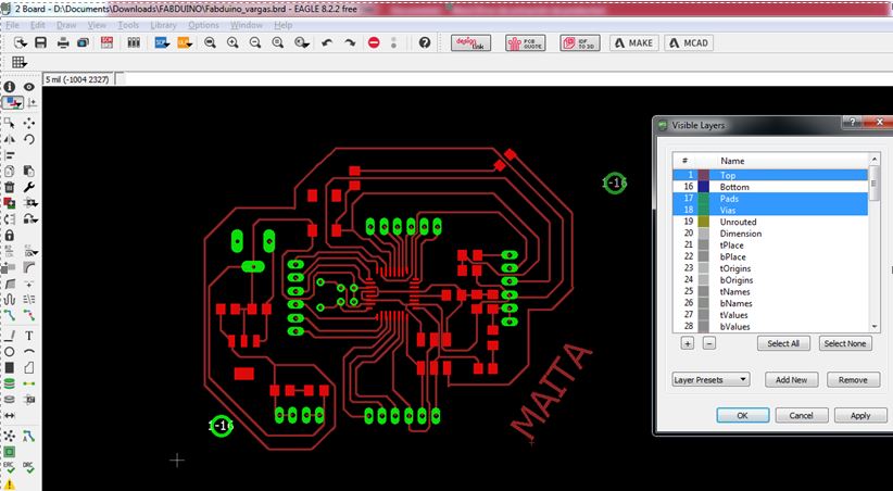
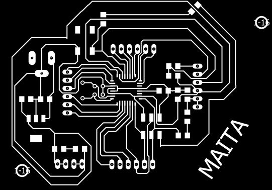
7 Then we need to visualize the layers TOP and PADS
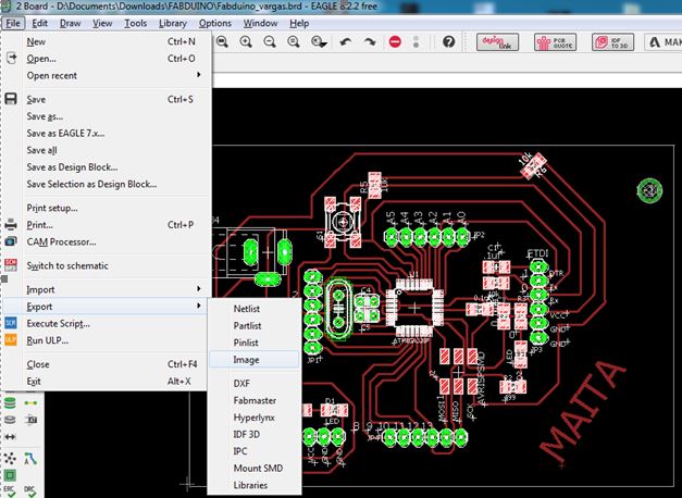
8 Then exported the design of my electronic circuit to a PNG file.
9 Name it, resolution of 2400 and we select monochrome.
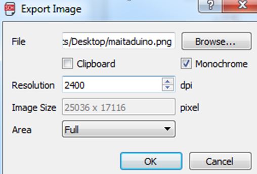
10 And finally generate my image in png format

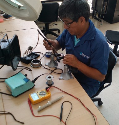
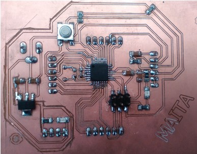
Welding the components of the electronic board
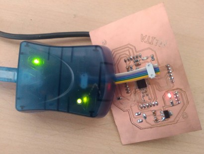
Verification, programming and loading Bootloader
        int estado = 'q';
        int led;
        int pin3=3;
        int pin4=4;
        int pin5=5;
        int pin6=6;
        void setup(){
        Serial.begin(9600);
        pinMode(pin3,OUTPUT);
        pinMode(pin4,OUTPUT);
        pinMode(pin5,OUTPUT);
        pinMode(pin6,OUTPUT);
      }

      void loop(){


      digitalWrite(pin3, LOW);
      digitalWrite(pin4,LOW);

      digitalWrite(pin5,LOW);
      digitalWrite(pin6,LOW);
      digitalWrite(11 ,LOW);
      delayMicroseconds(10);
      digitalWrite(11, HIGH);
      delayMicroseconds(10);
      tiempo=pulseIn(12, HIGH);
      distancia= int(0.017*tiempo);

      if(Serial.available()>0){
      estado = Serial.read();
    }
    if(estado=='w'){
    digitalWrite(pin3, LOW);
    digitalWrite(pin4,HIGH);

    digitalWrite(pin5,LOW);
    digitalWrite(pin6,HIGH);
    delay(1000);

  }
  if(estado=='a'){
  digitalWrite(pin3, LOW);
  digitalWrite(pin4,HIGH);

  digitalWrite(pin5,HIGH);
  digitalWrite(pin6,LOW);
  delay(1000);

}
if(estado=='d'){
digitalWrite(pin3, HIGH);
digitalWrite(pin4,LOW);

digitalWrite(pin5,LOW);
digitalWrite(pin6,HIGH);
delay(1000);
}
if (estado =='s'){
digitalWrite(pin3,HIGH);
digitalWrite(pin4,LOW);

digitalWrite(pin5,HIGH);
digitalWrite(pin6,LOW);
delay(1000);
}
if (estado =='q'){
digitalWrite(pin3, LOW);
digitalWrite(pin4,LOW);

digitalWrite(pin5,LOW);
digitalWrite(pin6,LOW);
delay(1000);
}

}
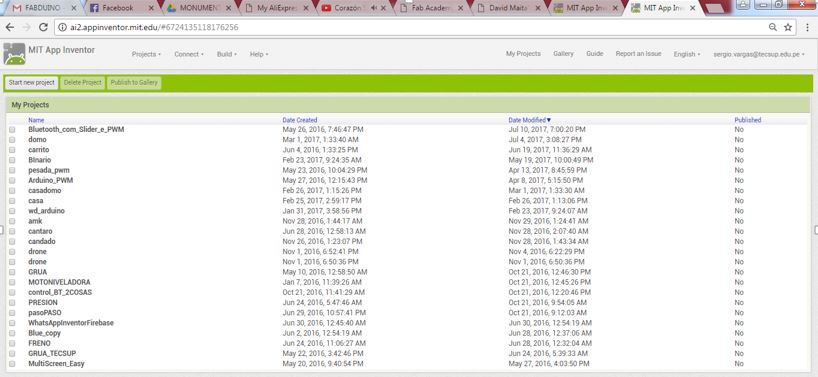
1 Open the APPinventor page (http://appinventor.mit.edu/explore/) and create an APP.
2 Then create a new project
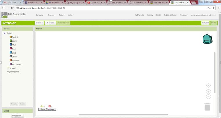
3 Once I have created a blank Screen appears, here we can design our App.
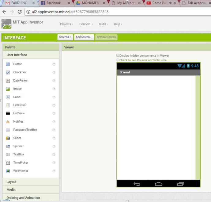
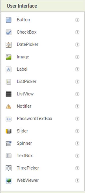
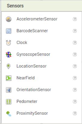
4 Then go to place the components that I need to design and control my application.
- ListPicker
-Label
-Button
-TextBox
-Clock
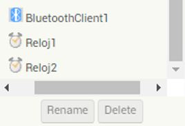
-Bluetooth Client
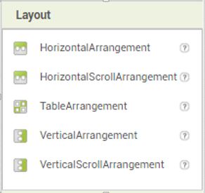
5 Once you have all the components, you need to place the components in order.
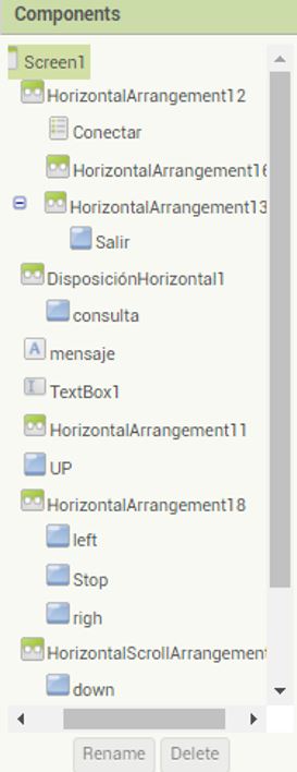
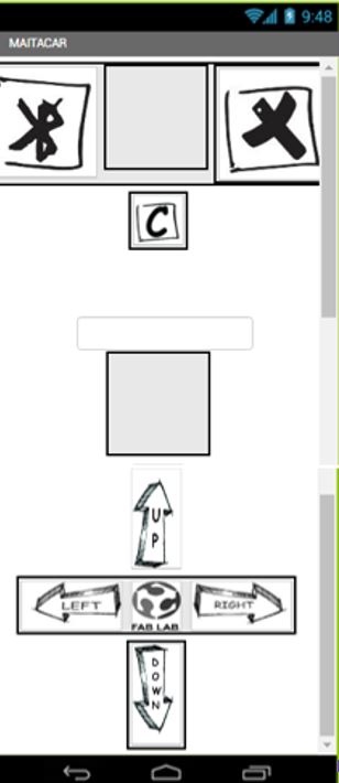
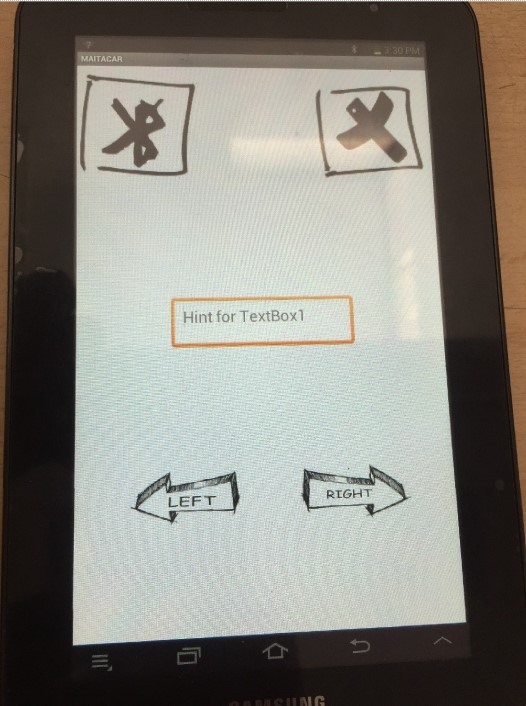
6 Then I order the buttons and put some images to make the app easier to understand.
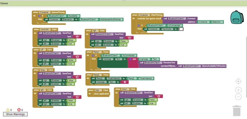
7 Then select the BLOCK option to open a blank window, where you program the application in blocks.
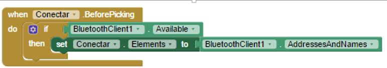
8 Then make the following block connections.
- programming block to select name and address of bluetooth
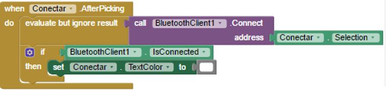
- programming block to connect to the bluetooth module
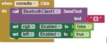
- programming block to send the letter "C" to Bluetooth
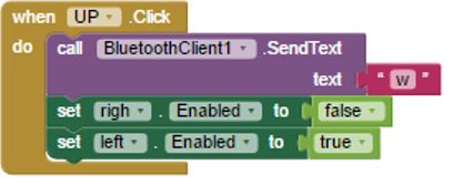
- programming block to send the letter "W" to Bluetooth
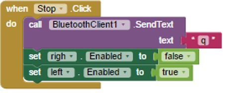
- programming block to send the letter "Q" to Bluetooth
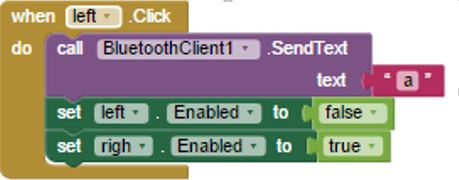
- programming block to send the letter "A" to Bluetooth
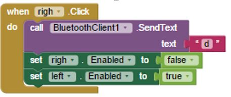
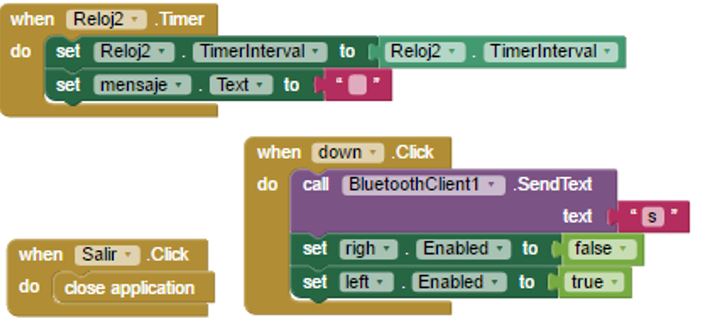
- programming block to send the letter "D" to Bluetooth
- programming block to receive data from the fabduino and display it in the Textbox
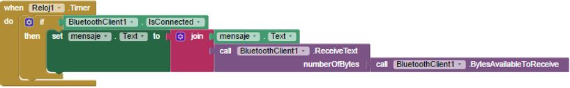
- block of programming to delete message of Textbox
9 Final result obtube the application, I also use it in my final project
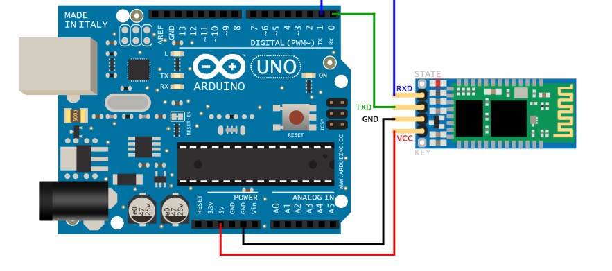
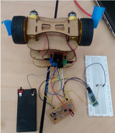
We connected the bluetooth module in this way.
Once the connection is made to the bluetooth module, a red light will start blinking.
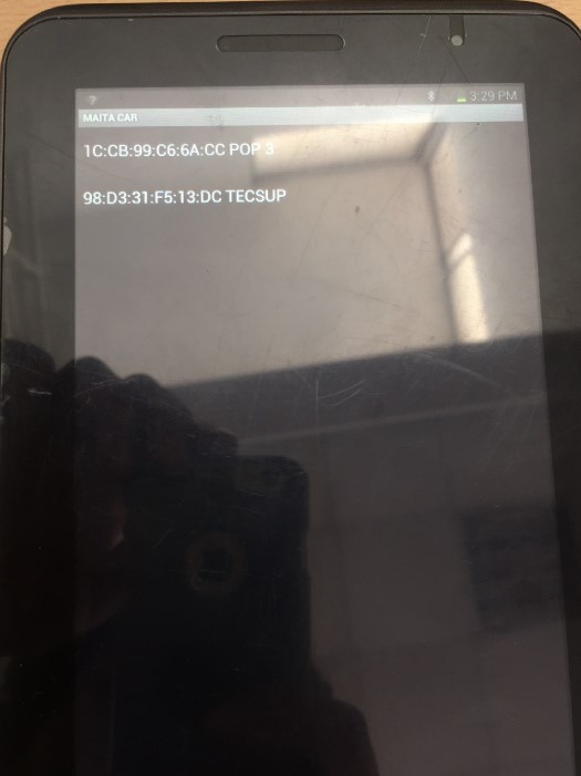
Then on a cellphone or Tablet "Android", we must enable the bluetooth option and look for our device in my case is called "Tecsup"

We link the bluetooth using the PIN code. Then open the application and press the bluetooth icon
We select our bluetooth device in my case is called "TECSUP" and our application is already synchronized with the bluetooth module
Schematic for device installation
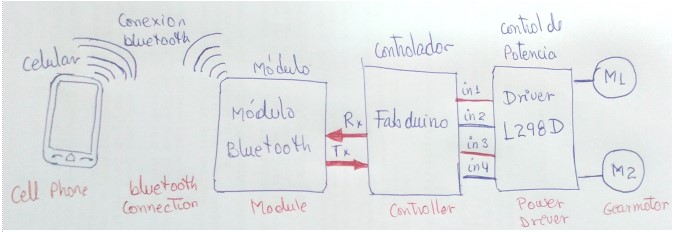
It is configured with blutooth module to synchronize with the mobile
Installation
-Install the communication interfaces
-Programmed the board to generate movements in both ways
-Programmed a variable speed.