Week13 : Input Devices
The assignment of this week :
● measure something: add a sensor to a microcontroller board that you have designed and read it.
● Demonstrate workflows used in circuit board design and fabrication.
● Implement and interpret programming protocols.
The workflew of measure somrthing is as follow:
1.Design a circuit board.
2.Connect with ISP, circuit board and input device.
3.Measure the input device.
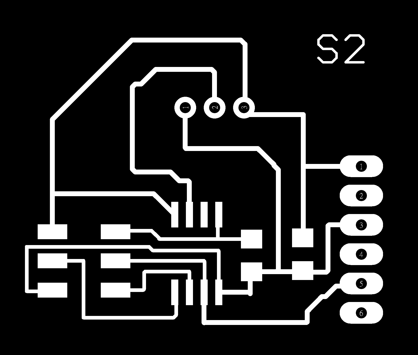
●Design a citcuit board
In this week, I try to change the microcontroller to ATmeag328. After reading the datasheet, I design the circuit board with Eagle and Milling it with Roland Modela MDX-20.
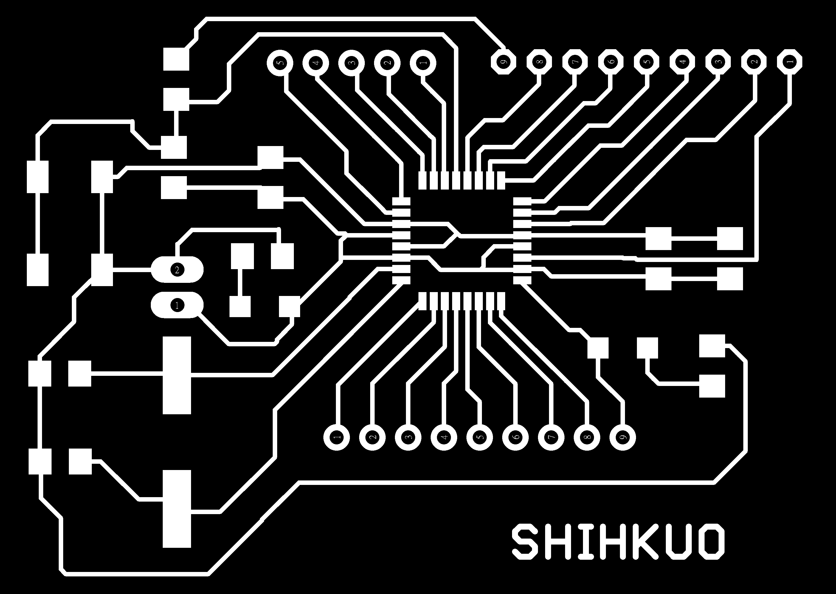
figure 1 : PCB design.
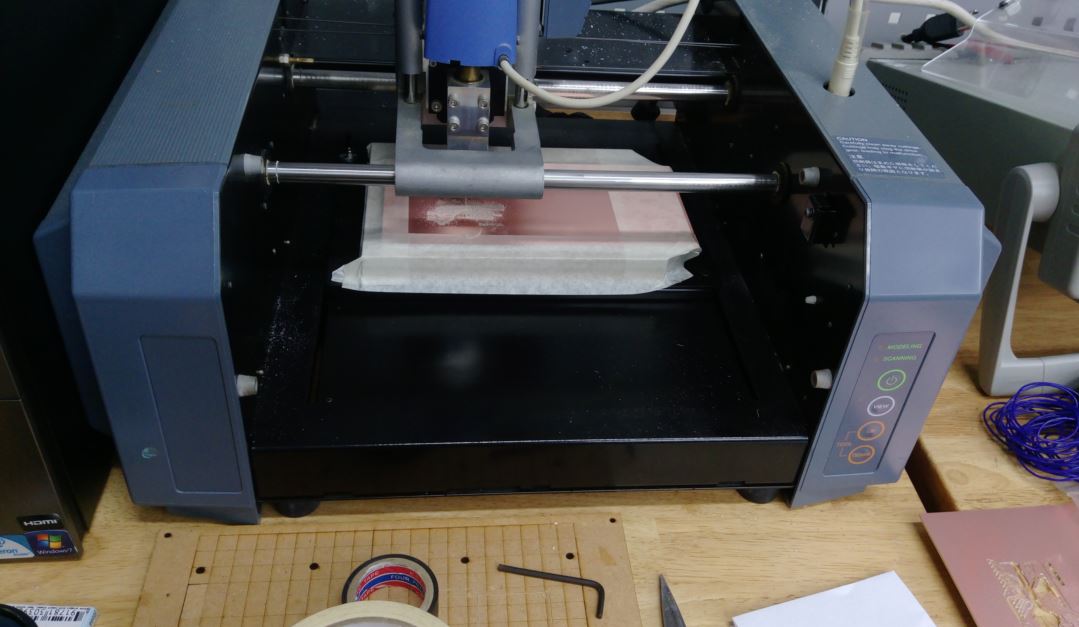
figure 2 : Milling PCB with Roland Modela MDX-20.
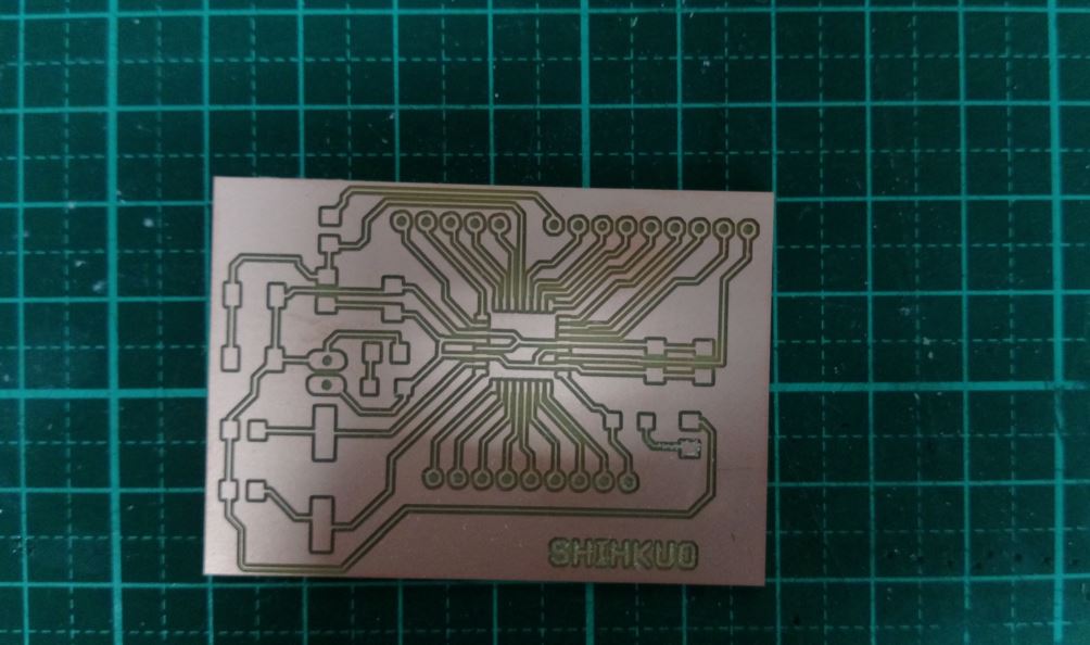
figure 3 : PCB.
I quickly found a problem, that was I did not design the RST pin and that would couse the problem while burning the bootloader. So I Manually added a RST pin on the PCB board and redraw the PCB.
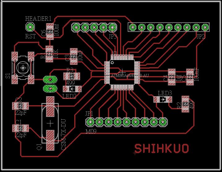
figure 4 : Redesign the PCB.
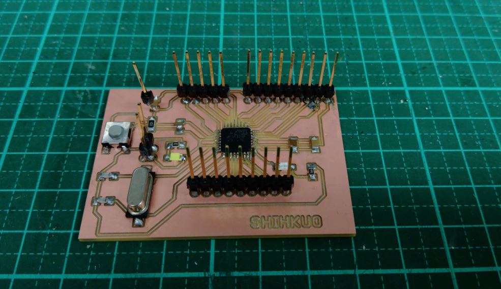
figure 5 : Manually add a RST pin on the PCB.
But I met a big problem, I could not burn the bootloader. I had checked the connection of each pin and it still would not work anyway. The board has been jumper very horrible, and I found there maybe the mistake of route design. I were about to run out of my time, so I decided to recheck and redesign this board later.
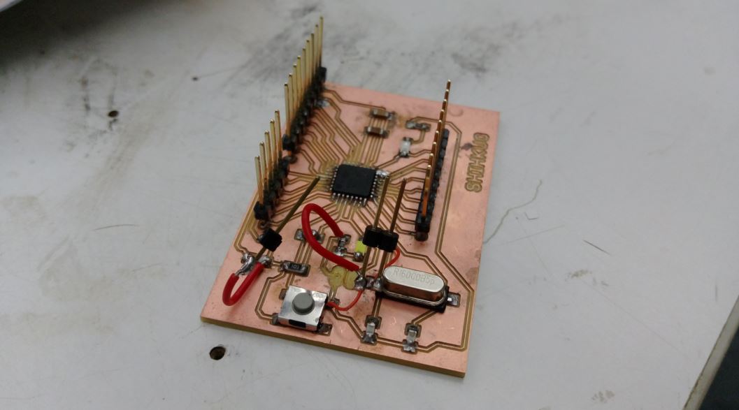
figure 6 : Horrible jumpers.
I follow the instruction to redraw a board with microcontroller ATtiny45, and milling and solder it.
figure 7 : Redrawed the board.
figure 8 : Milling the second board.
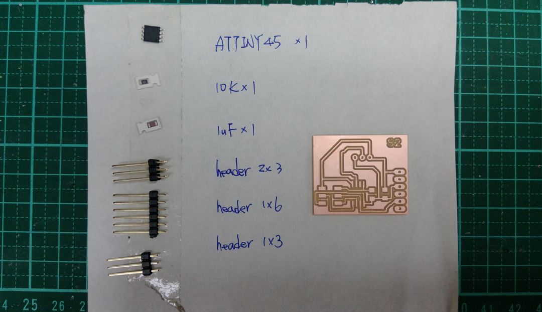
figure 9 : Components of the second board.
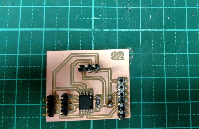
figure 10 : Second circuit board finished.
●Connect with ISP, circuit board and input device
Also, I use adruino UNO as the ISP and pyroelectric(PIR sensor) as the input device. It needs a FTDI usb cable to connect with circuit board and computer. I used a USB to RS232 cable with CH340G chip.
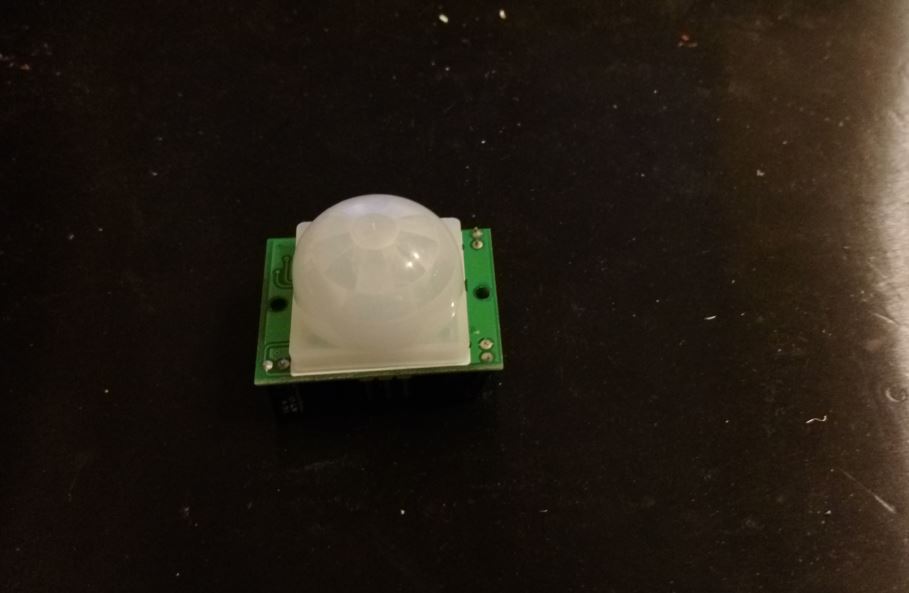
figure 11 : Pyroelectric as the input device.
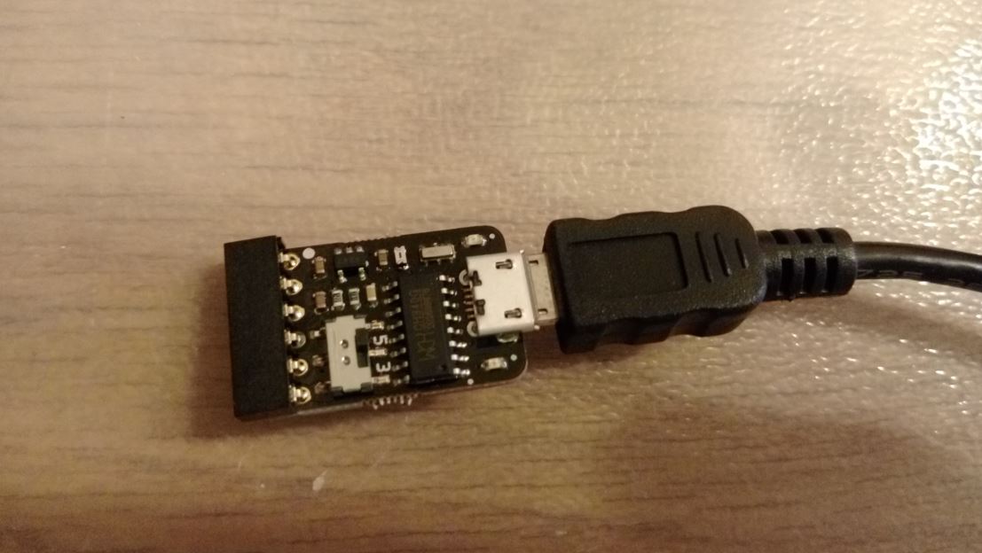
figure 12 : USB to RS232 cable with CH340G chip.
The first thing I need to know is the pinout of ATtiny45, and there is ainstruction about it on high-low tech website.
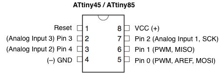
figure 13 : Pinout of ATtiny45.
The second step is to connect the arduino UNO and my circuit board,and the connection is as follows:
● ATtiny45 SCK Pin to Arduino Pin 13
● ATtiny45 MISO Pin to Arduino Pin 12
● ATtiny45 MOSI Pin to Arduino Pin 11
● ATtiy45 Reset Pin to Arduino Pin 10
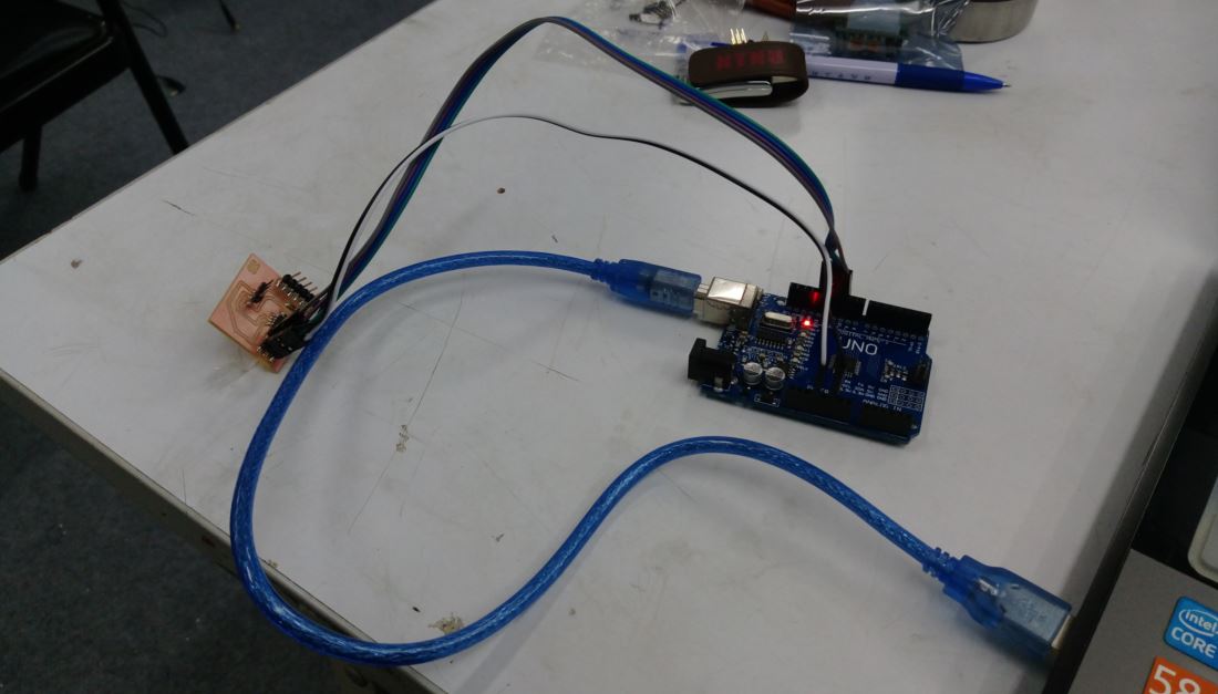
figure 14 : Connection between UNO and my circuit board.
There is a instruction about how the PIR sensor work on adafruit website. There are three pinouts on PIR sensor, VCC , OUT and GND. I connect VCC and GND to the VCC and GND pin of my board, and the OUT pin to the pin 4 of my circuit board.
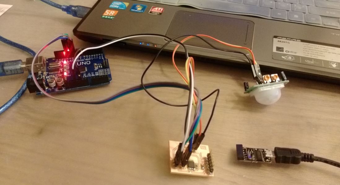
figure 15 : Connection between PIR sensor and my circuit board..
The FDTI-Cables documention shows the pinout and the connection between FDTI cable and circuit board. So I follow the direction to connect the FDTI cable.
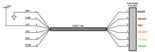
figure 16 : Connection between FDTI cable and circuit board.
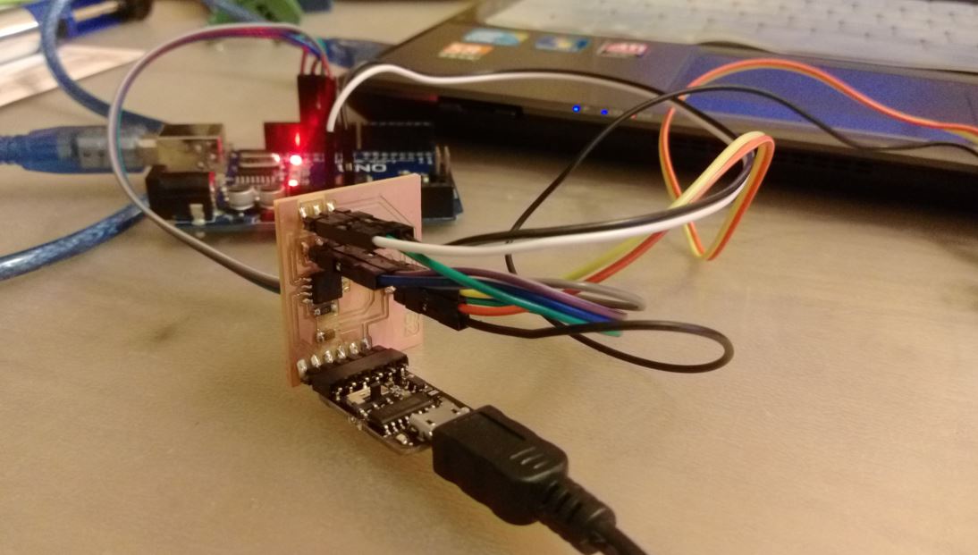
figure 17 : Connection between FDTI cable and circuit board.
●Programming and testing
I use the arduino IDE to burn the bootloader and program the circuit. There is a tutorial about the serial communcation on arduino website. So I writed a program the detect the PIR sensor. The function of the program is while the PIR sensor detects motion, the serial monitor prints "1", and prints "0" while no motion be detected.
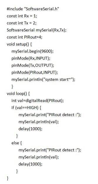
figure 18 : Codes of PIR sensor with arduino IDE.
The vedio of PIR sensor works is as follow:
●Source file
1.PNG file of the circuit board.
2.SCH file of the circuit board.
3.PCB of the circuit board.
4.Datasheet of ATtiny45.
5.Datasheet of FDTI-Cables.
5.Program of the PIR sensor.