week10 : Output Device
The assignment of this week :
Add an output device to a microcontroller board I've designed and program it to do something.
●Add an LCD to my board.
Since I went to Shenzhen to do the MTM project with my partners. So I decided to do this week's assignment with my partner too. I discussed with Ye Xiaohua and we decided to add an LCD and a speaker on our board. So our output device and board were similar.
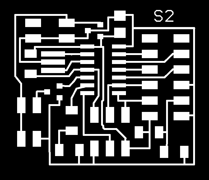
I just followed the instruction which showed on schedule. I added an LCD and a speaker circuit to my board. The PCB layout showed below:
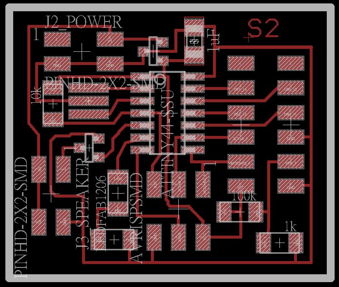
figure 1 : PCB layout.
After Soldering all of the components, we try to program the board. Because of the trainning of soldering and designing PCB few weeks ago, it did not spent us a long time to do it.
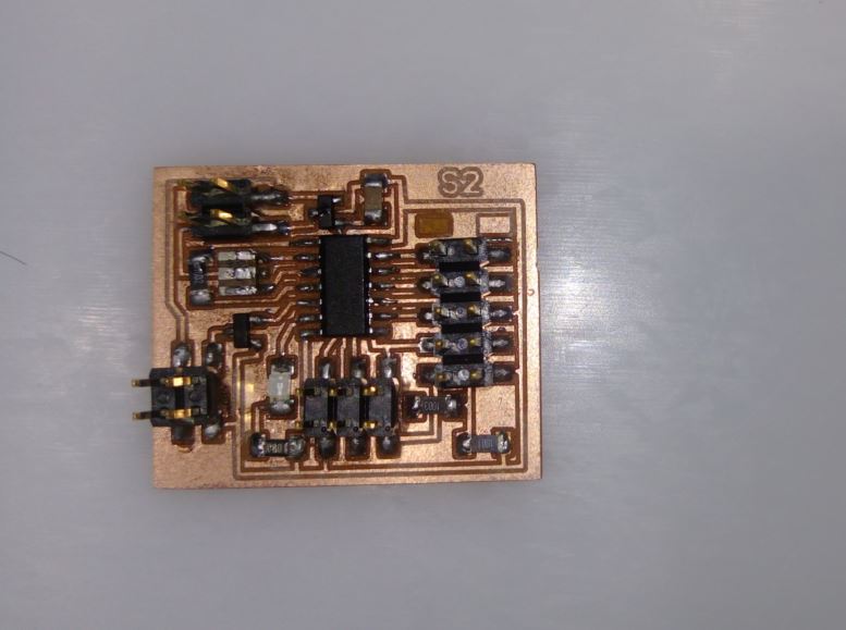
figure 2 : Soldering all components.
As usual, I chosed arduino UNO as the ISP to program my board. At first, we tried to make the speaker works. But we found the foorprints the MOSFET connected wrong. After fixed it, the speaker still did not work.
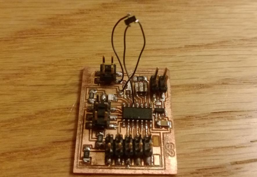
figure 3 : Fixed the connection with MOSFET.
After checking the hardware was fine, I recheck the program, there were two program on the arduino website described how to realize speaker function. I used the "toneMelody" function to test my board, it did not worked. So I tried another "PlayMelody" function to test my board, and it works. The difference between these two functions is the "PlayMelody" uses PWM to produce the tone. So, the pin which connected with the speaker needed has the PWM function. On ATtiny44, there only Pin 5, 6, 7, 8 had PWM function.
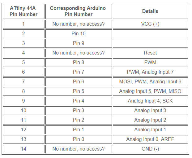
figure 4 : Footprint's function of ATtiny44.
Another output device, LCD, which has 16 pins and each pin has specific function. I just follow the tutorial which described on the arduino website.
The pins connection between Attiny44 and LCD were as following :
PA0 -> LCD 14(DB7)
PA1 -> LCD 13(DB6)
PA2 -> LCD 12(DB5)
PA3 -> LCD 11(DB4)
PA4 -> LCD 6(Enable signal)
PA5 -> LCD 4(Register select)
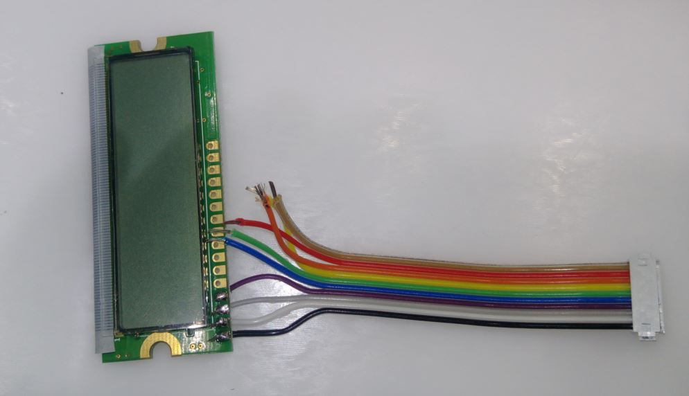
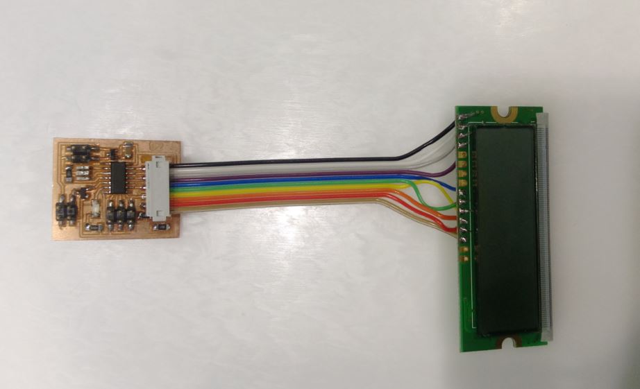
figure 5 : Connection with LCD and Attiny44 board.
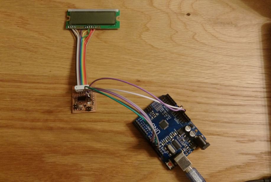
figure 6 : Connection with arduino UNO.
The LCD function I programed was showed "FadLab Taipei" on first row and "Shihkuo" on second row. Then the speaker showed some tones with led blinked. The codes showed below :
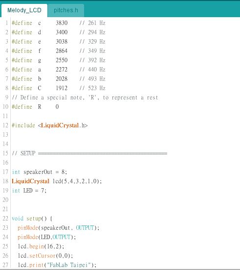
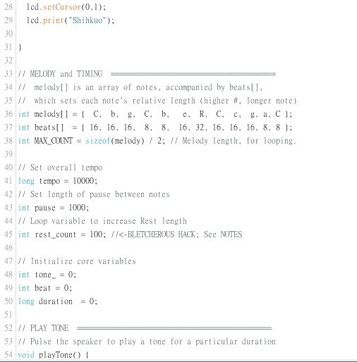
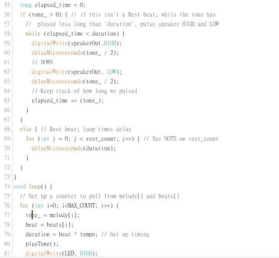
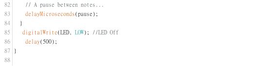
figure 7 : Codes.
And there has an vedio showed below, but the volume of the speaker quite small :
●Source file.
1.Schematic of my board.
2.PCB layout of my board.
3.Code for arduino.
4.Png file of traces.
5.Png file of interior.