Embedded programming
Assignment
Read a microcontroller data sheet.
Program your board to do something, with as many different programming languages and programming environments as possible.
Extra credit: experiment with other architectures
Read a microcontroller data sheet.
Program your board to do something, with as many different programming languages and programming environments as possible.
Extra credit: experiment with other architectures
Data Sheet
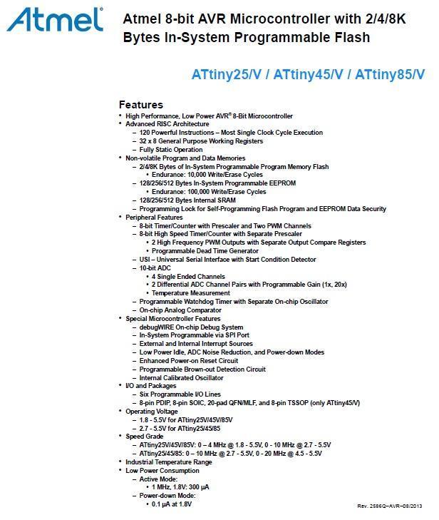
This week’s assignment is to first read a microcontroller data sheet. The microcontroller I use on the hello echo board is an Attiny85 from Atmel. The datasheet can be download from:
http://www.atmel.com/images/atmel-2586-avr-8-bit-microcontroller-attiny25-attiny45-attiny85_datasheet.pdf
This a 234 page pdf document, so first time reading to understand such a lengthy document can be quite daunting. There is a shorter, 30 page datasheet-summary which is a good place to start, it can be downloaded from:
http://www.atmel.com/Images/Atmel-2586-AVR-8-bit-Microcontroller-ATtiny25-ATtiny45-ATtiny85_Datasheet-Summary.pdf
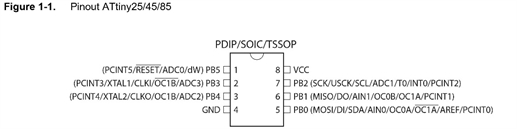
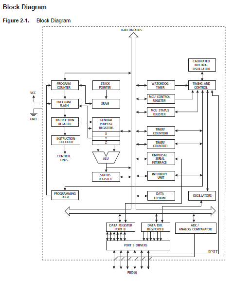
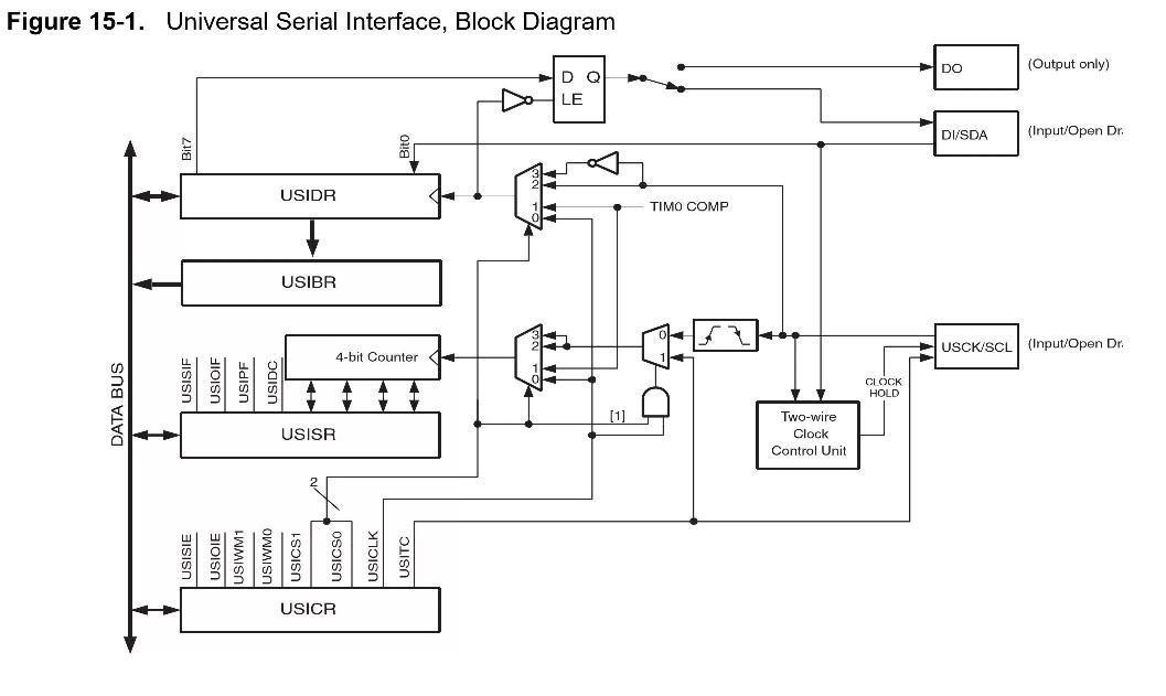
The most important picture in the data sheet is the Block Diagram which basically tell you what the microcontroller is about, and the most important part of the block diagram is the number of Input/Output pin available. This directly decides whether this particular microcontroller is suitable for the intended purpose.
My application basically requires the following:
1. An output pin for a LED.
2. An input pin for a push button.
3. A output pin as Transmitting pin.
4. A input pin as receiving pin.
All microcontroller also incurs the following operating overheads.
1. A Vcc power input pin.
2. A ground pin.
3. 2 pins for external clock.
Since I am not using external clock. I only needs the following:
An output pin for a LED.
An input pin for a push button.
A output pin as Transmitting pin.
A input pin as receiving pin.
A Vcc power input pin
A ground pin
So the Attiny85 is suitable. It should be noted that although it is always convenient to selected a more powerful microcontroller with many more Input/Output pins. It is actually a waste of hardware resources, a no-no in industrial application as it means making the end product unnecessarily expansive and thus less competitive.
In reality, there are far more considerations required when selecting a microcontroller. Some of major ones are as follow:
1. Speed (how fast to complete the task required).
2. Memory (to run lengthy program).
3. Power consumption (particular for mobile system on battery).
4. Operating environment.
5. Other specify features such as:
a) Analog to digital conversion.
b) Interrupts support.
c) Pulse width modulation.
d) Timer.
e) Counter.
f) External interface.
On the commercial aspect. Consideration on availability is important and cost/features.
More consideration if the microcontroller is going to be used in rugged environment such as military application.
This week’s assignment is to first read a microcontroller data sheet. The microcontroller I use on the hello echo board is an Attiny85 from Atmel. The datasheet can be download from:
http://www.atmel.com/images/atmel-2586-avr-8-bit-microcontroller-attiny25-attiny45-attiny85_datasheet.pdf
This a 234 page pdf document, so first time reading to understand such a lengthy document can be quite daunting. There is a shorter, 30 page datasheet-summary which is a good place to start, it can be downloaded from:
http://www.atmel.com/Images/Atmel-2586-AVR-8-bit-Microcontroller-ATtiny25-ATtiny45-ATtiny85_Datasheet-Summary.pdf
The most important picture in the data sheet is the Block Diagram which basically tell you what the microcontroller is about, and the most important part of the block diagram is the number of Input/Output pin available. This directly decides whether this particular microcontroller is suitable for the intended purpose.
My application basically requires the following:
1. An output pin for a LED.
2. An input pin for a push button.
3. A output pin as Transmitting pin.
4. A input pin as receiving pin.
All microcontroller also incurs the following operating overheads.
1. A Vcc power input pin.
2. A ground pin.
3. 2 pins for external clock.
Since I am not using external clock. I only needs the following:
An output pin for a LED.
An input pin for a push button.
A output pin as Transmitting pin.
A input pin as receiving pin.
A Vcc power input pin
A ground pin
So the Attiny85 is suitable. It should be noted that although it is always convenient to selected a more powerful microcontroller with many more Input/Output pins. It is actually a waste of hardware resources, a no-no in industrial application as it means making the end product unnecessarily expansive and thus less competitive.
In reality, there are far more considerations required when selecting a microcontroller. Some of major ones are as follow:
1. Speed (how fast to complete the task required).
2. Memory (to run lengthy program).
3. Power consumption (particular for mobile system on battery).
4. Operating environment.
5. Other specify features such as:
a) Analog to digital conversion.
b) Interrupts support.
c) Pulse width modulation.
d) Timer.
e) Counter.
f) External interface.
On the commercial aspect. Consideration on availability is important and cost/features.
More consideration if the microcontroller is going to be used in rugged environment such as military application.
Program your board to do something
A total of 3 Programming environment/programming language will be covered in this sector, they are:
1. UART programming with arduino softserial (ie: softserial.h)
2. UART programming without softserial
3. Mikro C IDE
4. Atmel Studio
I have demonstrated the use of AVRdude and GCC AVR-Lib in previous assignments, namely electronics production and electronics design, so for this assignment, I will start with the use of Arduino IDE programming environment and C programming language.
To programme the Attiny 85 in Arduino IDE, additional board support has to be included, this is documented in the following link:
Porgramming Atting with Arduino 1.6(1.0)
http://highlowtech.org/?p=1695
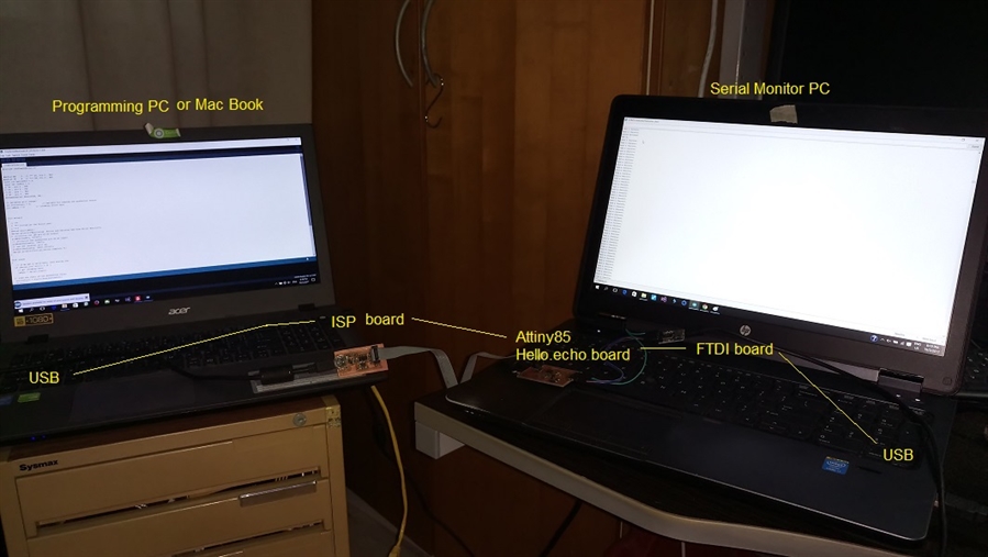
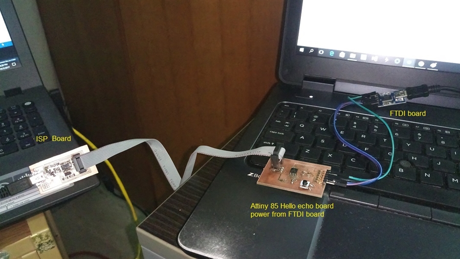
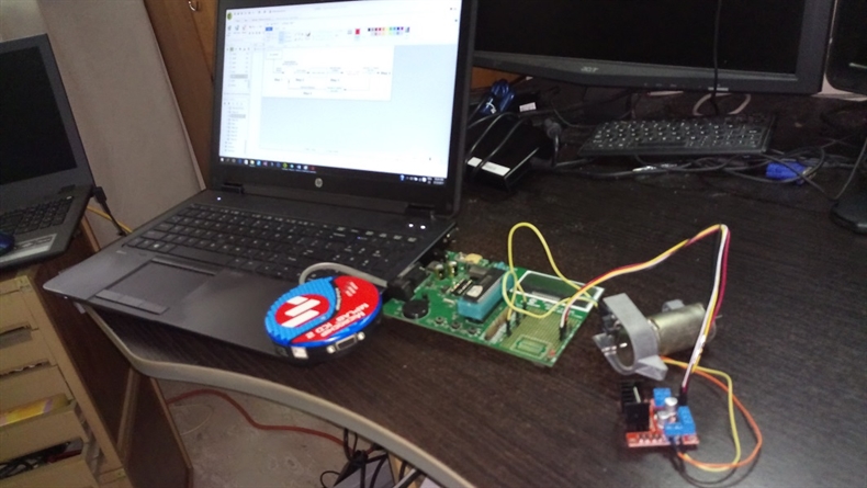
The components involves in this exercise are as follow:
1. Programming PC running Arduino IDE, Atmel studio or Macbook running crosspack etc...
2. ISP board
3. Echo Hello board with a LED and a button
4. FTDI board
5. Output monitoring PC running either serial monitor, Hyper terminal, Putty etc...
The reason for this setup is because ISP board and FTDI will use a USB connection each, you have switch back and forth on a single PC setup especially when there is a need to change code and recompile and reflash. I discovered that my FabISP was intermitant probably due to a padlift on the 3X2 header I repaired recently. so I switched to the Sparkfunc Pocket AVR programmer for the rest of the assignment. I will do a new PCB for the FabISP at a later time.
A total of 3 Programming environment/programming language will be covered in this sector, they are:
1. UART programming with arduino softserial (ie: softserial.h)
2. UART programming without softserial
3. Mikro C IDE
4. Atmel Studio
I have demonstrated the use of AVRdude and GCC AVR-Lib in previous assignments, namely electronics production and electronics design, so for this assignment, I will start with the use of Arduino IDE programming environment and C programming language.
To programme the Attiny 85 in Arduino IDE, additional board support has to be included, this is documented in the following link:
Porgramming Atting with Arduino 1.6(1.0)
http://highlowtech.org/?p=1695
The components involves in this exercise are as follow:
1. Programming PC running Arduino IDE, Atmel studio or Macbook running crosspack etc...
2. ISP board
3. Echo Hello board with a LED and a button
4. FTDI board
5. Output monitoring PC running either serial monitor, Hyper terminal, Putty etc...
The reason for this setup is because ISP board and FTDI will use a USB connection each, you have switch back and forth on a single PC setup especially when there is a need to change code and recompile and reflash. I discovered that my FabISP was intermitant probably due to a padlift on the 3X2 header I repaired recently. so I switched to the Sparkfunc Pocket AVR programmer for the rest of the assignment. I will do a new PCB for the FabISP at a later time.
Programming in Arduino IDE
Since Attiny85 is without a hardware UART, I will try using the software serial library with internal clock. The purpose of the code on the microcontroller is to ask the serial monitor to send a character by keep sending a message “send a character.”. When user send a character, the microcontroller will read the status on the button at PB2. If the button is released, the LED at PB1 will be switched on. A message “Button released” follows by another message “LED On” will be sent to the serial monitor.
Similarly, if the button is pressed, the LED will be switched off and 2 messages “Button pressed” and “LED off” will be send.
The code is shown below.
//TinySerialButtonLED.ino
//
//By: Phay Ngiap Peng. Kenny
//
//19 Mar 2017, Rev 0
//
#include <SoftwareSerial.h>
#define RX 3 // *** D3, Pin 2 , PB3
#define TX 4 // *** D4, Pin 3 , PB4
const int buttonPin = 2;
const int ledPin = 1;
// D0 , pin 5 , PB0
// D1 , pin 6 , PB1
// D2 , pin 7 , PB2
// D5 , pin 5 , PB5
SoftwareSerial Serial(RX, TX);
// variables will change:
int buttonState = 0; // variable for reading the pushbutton status
int inByte = 0; // incoming serial byte
void setup()
{
// ***
// *** Initialize the Serial port
// ***
Serial.begin(9600);
Serial.println("Monitoring Button and Swiching LED From Serial Monitor");
// initialize the LED pin as an output:
pinMode(ledPin, OUTPUT);
// initialize the pushbutton pin as an input:
pinMode(buttonPin, INPUT);
// use the internal pull up:
pinMode(buttonPin, INPUT_PULLUP);
Serial.println("Initialization complete.");
}
void loop()
{
// if we get a valid byte, read analog ins:
if (Serial.available() > 0) {
// get incoming byte:
inByte = Serial.read();
// read the state of the pushbutton value:
buttonState = digitalRead(buttonPin);
//delay(10);
// check if the pushbutton is pressed.
// if it is, the buttonState is HIGH:
if (buttonState == HIGH) {
// turn LED on:
digitalWrite(ledPin, HIGH);
Serial.println("Button Released.");
Serial.println("LED On.");
} else {
// turn LED off:
digitalWrite(ledPin, LOW);
Serial.println("Button Pressed.");
Serial.println("LED Off.");
}
}
Serial.println("Send a charater.");
}
//
//By: Phay Ngiap Peng. Kenny
//
//19 Mar 2017, Rev 0
//
#include <SoftwareSerial.h>
#define RX 3 // *** D3, Pin 2 , PB3
#define TX 4 // *** D4, Pin 3 , PB4
const int buttonPin = 2;
const int ledPin = 1;
// D0 , pin 5 , PB0
// D1 , pin 6 , PB1
// D2 , pin 7 , PB2
// D5 , pin 5 , PB5
SoftwareSerial Serial(RX, TX);
// variables will change:
int buttonState = 0; // variable for reading the pushbutton status
int inByte = 0; // incoming serial byte
void setup()
{
// ***
// *** Initialize the Serial port
// ***
Serial.begin(9600);
Serial.println("Monitoring Button and Swiching LED From Serial Monitor");
// initialize the LED pin as an output:
pinMode(ledPin, OUTPUT);
// initialize the pushbutton pin as an input:
pinMode(buttonPin, INPUT);
// use the internal pull up:
pinMode(buttonPin, INPUT_PULLUP);
Serial.println("Initialization complete.");
}
void loop()
{
// if we get a valid byte, read analog ins:
if (Serial.available() > 0) {
// get incoming byte:
inByte = Serial.read();
// read the state of the pushbutton value:
buttonState = digitalRead(buttonPin);
//delay(10);
// check if the pushbutton is pressed.
// if it is, the buttonState is HIGH:
if (buttonState == HIGH) {
// turn LED on:
digitalWrite(ledPin, HIGH);
Serial.println("Button Released.");
Serial.println("LED On.");
} else {
// turn LED off:
digitalWrite(ledPin, LOW);
Serial.println("Button Pressed.");
Serial.println("LED Off.");
}
}
Serial.println("Send a charater.");
}

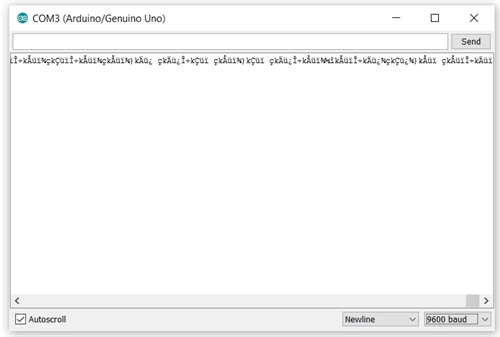
Problem encountered
The Attiny 85 comes without a hardware UART. There were instances that garbage was displayed on the serial monitor. This is likely due to timing of pulse on which the serial message was sent is out of synchronisation due to inaccuracy of the internal clock. This was mentioned by Neil during the lesson that internal clock has a +-10% tolerance. It appears that the VCC voltage and temperature have an effect on the internal clock.
There are a few ways to overcome this problem. One is to use an external oscillator, this means 2 pins of the microcontroller will be occupied. Another option is to tune the internal clock. The detail on how to tune the internal clock can be found from the link below:
Tuning ATtiny internal oscillator
http://becomingmaker.com/tuning-attiny-oscillator/
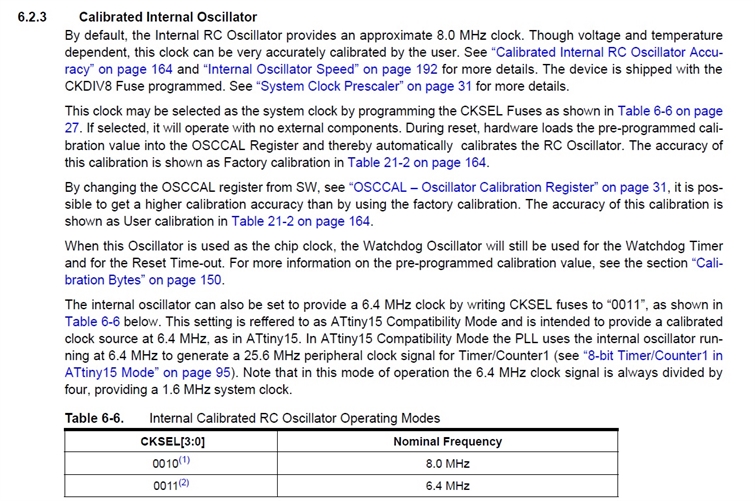
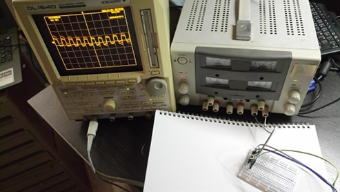
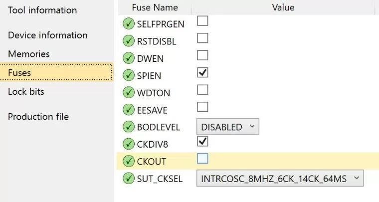
Tuning of the internal oscillator is controlled by the oscillator calibration register, OSCCAL. The simplest approach is to set the CKOUT fuse (bit 6 of the LOW fuse register) which will send the clock signal to PB4. Then you can use your oscilloscope or frequency counter to see how close you are to the selected frequency. This is also documented in the datasheet as shown below:
Setting the fuses of Attiny incorrectly risks bricking the microcontroller, so I decided not to do it on the hello echo board. Rather I would use the DIP Attiny85 that I have for this purpose. I spent the whole staturday aftenoon and evening playing with this.
The Attiny 85 comes without a hardware UART. There were instances that garbage was displayed on the serial monitor. This is likely due to timing of pulse on which the serial message was sent is out of synchronisation due to inaccuracy of the internal clock. This was mentioned by Neil during the lesson that internal clock has a +-10% tolerance. It appears that the VCC voltage and temperature have an effect on the internal clock.
There are a few ways to overcome this problem. One is to use an external oscillator, this means 2 pins of the microcontroller will be occupied. Another option is to tune the internal clock. The detail on how to tune the internal clock can be found from the link below:
Tuning ATtiny internal oscillator
http://becomingmaker.com/tuning-attiny-oscillator/
Tuning of the internal oscillator is controlled by the oscillator calibration register, OSCCAL. The simplest approach is to set the CKOUT fuse (bit 6 of the LOW fuse register) which will send the clock signal to PB4. Then you can use your oscilloscope or frequency counter to see how close you are to the selected frequency. This is also documented in the datasheet as shown below:
Setting the fuses of Attiny incorrectly risks bricking the microcontroller, so I decided not to do it on the hello echo board. Rather I would use the DIP Attiny85 that I have for this purpose. I spent the whole staturday aftenoon and evening playing with this.
Serial Programming without Arduino softserial library
Here is the code I have downloaded and modified, it can run on the Attiny85. it uses interupt routine for the serial interface.
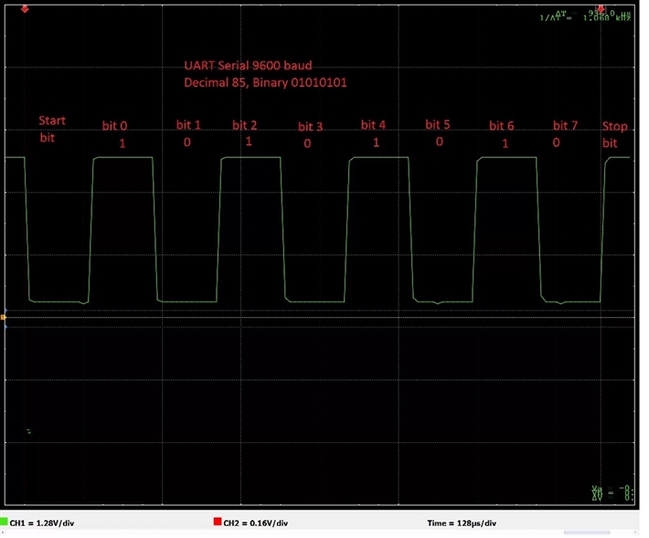
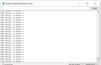
Basically this is how the program works, It sends via PB1 the message "OSI Seral. it works!!!"
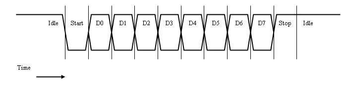
The data format for serial character is shown below.
start(low)-[0]-[1]-[2]-[3]-[4]-[5]-[6]-[7]-stop(high)-idle(high)-idle(high)
Many ATtiny microprocessors don’t include a hardware UART, but do include a Universal Serial Interface, USI. The USI module can be used to implement SPI, TWI (also known as I2C) and UART serial interfaces. This post describes how to implement a simple UART receiver using the USI module.
The detail working of the program is explain in the following links:
http://becomingmaker.com/usi-serial-uart-attiny85/
http://becomingmaker.com/usi-serial-send-attiny/
Atmel describe how to use the USI to implement a serial UART for an ATtiny26 in app note AVR307. This provides great information and is worth a read. They also provide the source code at www.atmel.com/images/AVR307.zip. Only thing is that this approach can only works on PB0 and PB1 on the Attiny85. For testing, PB0 and PB1 can be accessed via the 2x3 ISP connector.
Here is the code I have downloaded and modified, it can run on the Attiny85. it uses interupt routine for the serial interface.
Basically this is how the program works, It sends via PB1 the message "OSI Seral. it works!!!"
The data format for serial character is shown below.
start(low)-[0]-[1]-[2]-[3]-[4]-[5]-[6]-[7]-stop(high)-idle(high)-idle(high)
Many ATtiny microprocessors don’t include a hardware UART, but do include a Universal Serial Interface, USI. The USI module can be used to implement SPI, TWI (also known as I2C) and UART serial interfaces. This post describes how to implement a simple UART receiver using the USI module.
The detail working of the program is explain in the following links:
http://becomingmaker.com/usi-serial-uart-attiny85/
http://becomingmaker.com/usi-serial-send-attiny/
Atmel describe how to use the USI to implement a serial UART for an ATtiny26 in app note AVR307. This provides great information and is worth a read. They also provide the source code at www.atmel.com/images/AVR307.zip. Only thing is that this approach can only works on PB0 and PB1 on the Attiny85. For testing, PB0 and PB1 can be accessed via the 2x3 ISP connector.
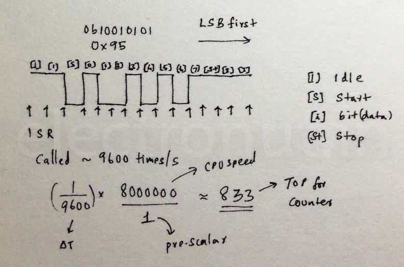
We need to choose the right Prescaler value for the regular ATtiny clock speeds of 1MHz, 8MHz and 16Mz and a range of common UART baud rates of such as 9600, 14400, 28800, 57600, 115200 and 230400. For example 9600 baud is 1666 CPU cycles at 16MHz, which is 208.25 when divided by 8, 208 whole CPU cycles with a 0.12% drift.
When setting the baud rate and CPU clock speed you will want the timer to be as accurate as possible, keeping drift below 5%. So higher baud rates won’t be available at lower CPU speeds. For example 230400 baud with a 1MHz clock is 4.34 CPU cycles (1000000/230400) which is just 4 whole CPU cycles with a 34% drift. And that’s before we take code execution time into account.
We define the clock speed, F_CPU, and the baud rate. Note F_CPU is already defined in Arduino and may already be defined in your development environment, it’s normally defined as a build symbol.
We define the clock speed, F_CPU, and the baud rate. Note F_CPU is already defined in Arduino and may already be defined in your development environment, it’s normally defined as a build symbol.
#define F_CPU 8000000
#define BAUDRATE 9600
We can use these to calculate the number of CPU clock cycles per bit width.
#define CYCLES_PER_BIT ( F_CPU / BAUDRATE )
If this number is 255 or less then we set the clock source to be the CPU clock, otherwise we will use the prescaler to divide the clock input to Timer/Counter0 by 8.
We use the bottom three Clock Select bits of Timer/Counter0 Control Register B, TCCR0B, to configure the prescaler. A Clock Select value of 1 is for the CPU clock and a value of 2 is for CPU clock divided by 8.
#if (CYCLES_PER_BIT > 255)
#define DIVISOR 8
#define PRESCALE 2
#else
#define DIVISOR 1
#define PRESCALE 1
#endif
#define FULL_BIT_TICKS ( CYCLES_PER_BIT / DIVISOR )
The USI module is optimized for use in either Two Wire I2C or Three Wire SPI mode, it doesn’t have a dedicated mode for UART. However the USI module is flexible enough that we can use an internal clock to trigger the USI to left shift the data bits into the USI data register.
We can use a pin change interrupt to detect the beginning of the start bit and then configure the USI to sample the value of the input pin in the center of each of the eight bits. We can then read the back the eight bit values that the USI shifted into the USI register and reverse them to get the original byte value.
/*
Original Author: Mark Osborne
Modified by Phay Ngiap Peng.Kenny
An example of USI Serial Send for ATtiny25/45/85.
Sends a text message every second.
ATTiny85 Hookup
RESET -|1 v 8|- Vcc
PB3 -|2 7|- PB2/SCK
PB4 -|3 6|- PB1/MISO/DO
GND -|4 _ 5|- PB0/MOSI/SDA
ATTiny85 PB1/MISO/DO = Serial UART Tx -> connect to Rx of serial output device
*/
/* Supported combinations:
* F_CPU 1000000 BAUDRATE 1200, 2400
* F_CPU 8000000 BAUDRATE 9600, 19200
* F_CPU 16000000 BAUDRATE 9600, 19200, 28800, 38400
*/
// Set your baud rate and number of stop bits here
#define BAUDRATE 9600
#define STOPBITS 1
//F_CPU defined by Arduino, e.g. 1000000, 8000000, 16000000
//#define F_CPU 8000000
// If bit width in cpu cycles is greater than 255 then divide by 8 to fit in timer
// Calculate prescaler setting
#define CYCLES_PER_BIT ( (F_CPU) / (BAUDRATE) )
#if (CYCLES_PER_BIT > 255)
#define DIVISOR 8
#define CLOCKSELECT 2
#else
#define DIVISOR 1
#define CLOCKSELECT 1
#endif
#define FULL_BIT_TICKS ( (CYCLES_PER_BIT) / (DIVISOR) )
// Old timer values
#ifdef ARDUINO
volatile static uint8_t oldTCCR0A;
volatile static uint8_t oldTCCR0B;
volatile static uint8_t oldTCNT0;
#endif
// USISerial send state variable and accessors
enum USISERIAL_SEND_STATE { AVAILABLE, FIRST, SECOND };
static volatile enum USISERIAL_SEND_STATE usiserial_send_state = AVAILABLE;
static inline enum USISERIAL_SEND_STATE usiserial_send_get_state(void)
{
return usiserial_send_state;
}
static inline void usiserial_send_set_state(enum USISERIAL_SEND_STATE state)
{
usiserial_send_state=state;
}
bool usiserial_send_available()
{
return usiserial_send_get_state()==AVAILABLE;
}
// Transmit data persistent between USI OVF interrupts
static volatile uint8_t usiserial_tx_data;
static inline uint8_t usiserial_get_tx_data(void)
{
return usiserial_tx_data;
}
static inline void usiserial_set_tx_data(uint8_t tx_data)
{
usiserial_tx_data = tx_data;
}
static uint8_t reverse_byte (uint8_t x) {
x = ((x >> 1) & 0x55) | ((x << 1) & 0xaa);
x = ((x >> 2) & 0x33) | ((x << 2) & 0xcc);
x = ((x >> 4) & 0x0f) | ((x << 4) & 0xf0);
return x;
}
void usiserial_send_byte(uint8_t data)
{
while (usiserial_send_get_state() != AVAILABLE)
{
// Spin until we finish sending previous packet
};
usiserial_send_set_state(FIRST);
usiserial_set_tx_data(reverse_byte(data));
// Save current Arduino timer state
#ifdef ARDUINO
oldTCCR0B = TCCR0B;
oldTCCR0A = TCCR0A;
oldTCNT0 = TCNT0;
#endif
// Configure Timer0
TCCR0A = 2<<WGM00; // CTC mode
TCCR0B = CLOCKSELECT; // Set prescaler to clk or clk /8
GTCCR |= 1 << PSR0; // Reset prescaler
OCR0A = FULL_BIT_TICKS; // Trigger every full bit width
TCNT0 = 0; // Count up from 0
// Configure USI to send high start bit and 7 bits of data
USIDR = 0x00 | // Start bit (low)
usiserial_get_tx_data() >> 1; // followed by first 7 bits of serial data
USICR = (1<<USIOIE)| // Enable USI Counter OVF interrupt.
(0<<USIWM1)|(1<<USIWM0)| // Select three wire mode to ensure USI written to PB1
(0<<USICS1)|(1<<USICS0)|(0<<USICLK); // Select Timer0 Compare match as USI Clock source.
DDRB |= (1<<PB1); // Configure USI_DO as output.
USISR = 1<<USIOIF | // Clear USI overflow interrupt flag
(16 - 8); // and set USI counter to count 8 bits
}
// USI overflow interrupt indicates we have sent a buffer
ISR (USI_OVF_vect) {
if (usiserial_send_get_state() == FIRST)
{
usiserial_send_set_state(SECOND);
USIDR = usiserial_get_tx_data() << 7 // Send last 1 bit of data
| 0x7F; // and stop bits (high)
USISR = 1<<USIOIF | // Clear USI overflow interrupt flag
(16 - (1 + (STOPBITS))); // Set USI counter to send last data bit and stop bits
}
else
{
PORTB |= 1 << PB1; // Ensure output is high
DDRB |= (1<<PB1); // Configure USI_DO as output.
USICR = 0; // Disable USI.
USISR |= 1<<USIOIF; // clear interrupt flag
//Restore old timer values for Arduino
#ifdef ARDUINO
TCCR0A = oldTCCR0A;
TCCR0B = oldTCCR0B;
// Note Arduino millis() and micros() will lose the time it took us to send a byte
// Approximately 1ms at 9600 baud
TCNT0 = oldTCNT0;
#endif
usiserial_send_set_state(AVAILABLE);
}
}
void setup() {
pinMode(1,HIGH); // Configure USI_DO as output.
digitalWrite(1,HIGH); // Ensure serial output is high when idle
}
void loop() {
char message[] = "USI Serial, it works!!!! ";
uint8_t len = sizeof(message)-1;
for (uint8_t i = 0; i<len; i++)
{
while (!usiserial_send_available())
{
// Wait for last send to complete
}
usiserial_send_byte(message[i]);
}
delay(1000);
}
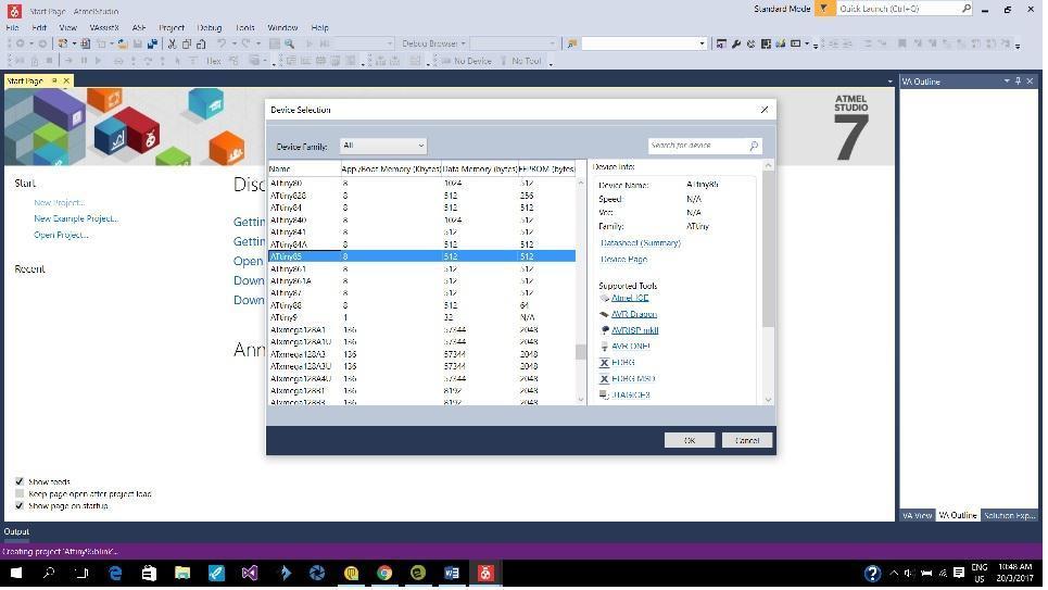
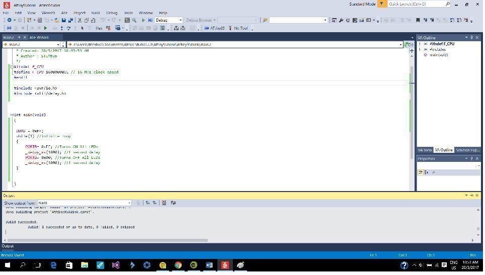
Programming in Atmel Studio
Atmel Studio is the offical programming tool for Atmel microcontroller, it is able to run on windows PC. To find out how to use Atmel Studio, the following links are useful.
AVR ATtiny85 Programming: Blink LED (Digital Output)
https://www.youtube.com/watch?v=SxJZGqToqu4
Using a USBTiny Programmer with Atmel Studio
https://www.youtube.com/watch?v=Af5P79IzcyE
I have enough fun with the UART serial communication experiments, so the rest of the operating environment and programming language exercise, I would just do a good old LED blinking routine.
Atmel Studio is a very versatile programming environment using the Visual C++ UI. It allow fuse setting, something no readily available on the Arduino IDE environment.
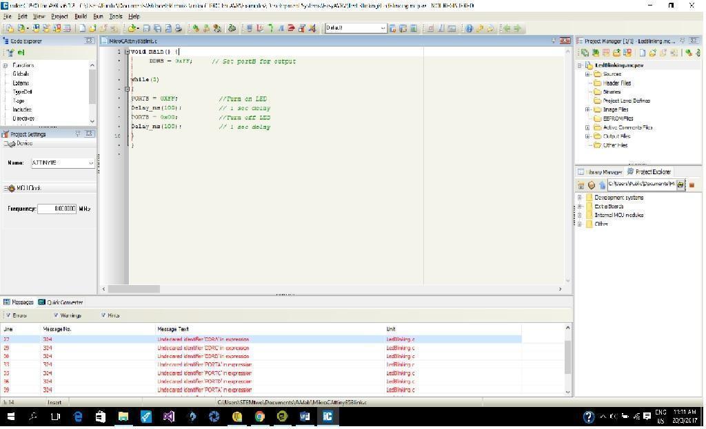
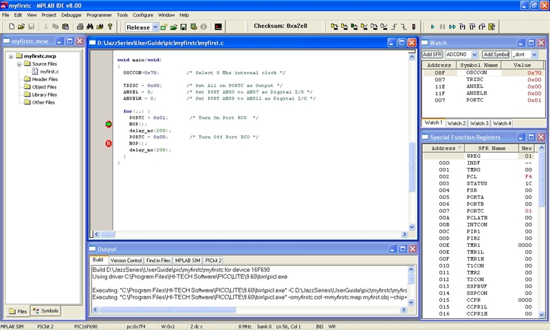
Programming in Mikro C
mikroC is a full-featured ANSI C compiler for 7 different microcontroller architectures: PIC, dsPIC, PIC32, STM32 ARM, Kinetis ARM, FT90x, AVR and 8051.
mikroC is a full-featured ANSI C compiler for 7 different microcontroller architectures: PIC, dsPIC, PIC32, STM32 ARM, Kinetis ARM, FT90x, AVR and 8051.
Experiment with other architectures
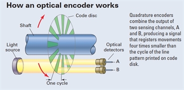
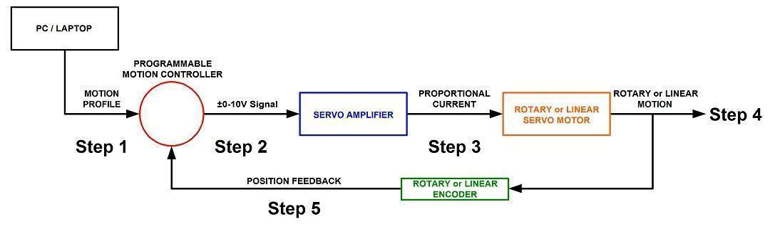
Microchip PIC18F4431 is an 8 bit microcontroller with Quadrature Encoder Interface,
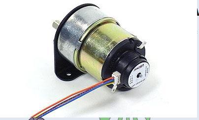
This means that optical encoder can be directly connected to the microcontroller forming a closed loop PID servo control system.
Microchip PIC18F4431 is an 8 bit microcontroller with Quadrature Encoder Interface,
This means that optical encoder can be directly connected to the microcontroller forming a closed loop PID servo control system.
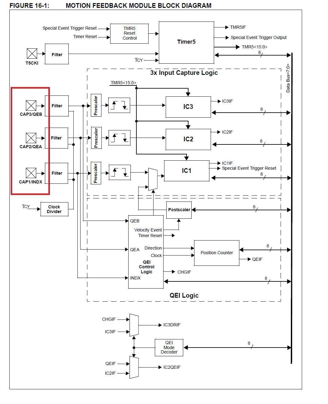

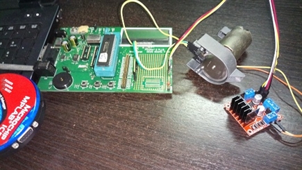
For my final project, a robot arm, using a closed loop servo system means that there is always monitoring of the positions of all the servo motors, even when the power to the motor drivers are switch off. All time positional monitoring allow the robot arm to be programmed by just moving the robot arm around by hand. This is something not possible with stepper motor control.
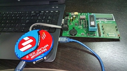
The Microchip PIC series of microcontrollers have its own development environment. The IDE is known as MPLAB and the programmer is called an ICD.
The PIC18F4431/4331 is a 8 bit microcontroller, there is also 16 bit microcontroller a upgrade option if more computing power is required.
The using of PIC 18F4431/4331 is still a work in progress. It will take some time to develop the PID control algorithm.
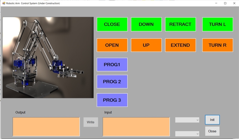
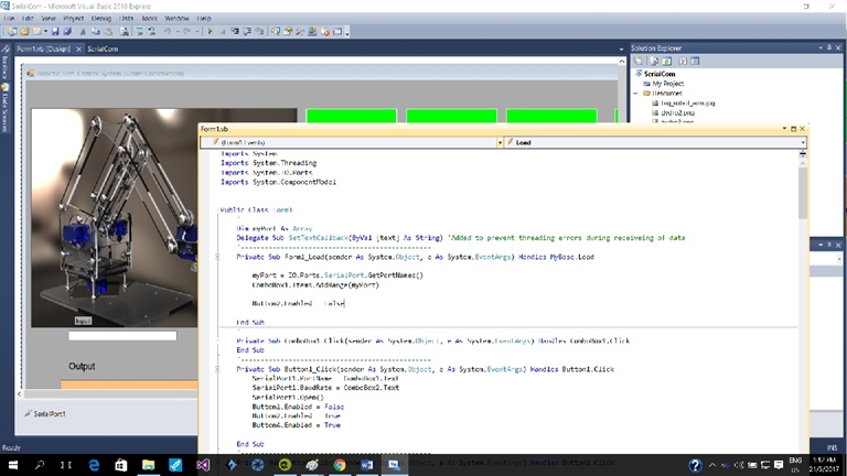
A custom graphical serial PC terminal
Standard serial terminal such as serial monitor on Arduio IDE, Hyper terminal on PC, cool term on Mac book are fine programs for sending and receiving messages between PC and microcontroller. However a custom software can also be developed to provide graphical user interface (GUI) when make the control and communication of microcontroller based equipment easier and more intuitive.
This example is a Visual Basic program I have written as a potential PC control for my final project, a robotic arm.
Reflection
The Attiny 84/85 series of microcontroller don’t come with a hardware UART. To implement software UART, an accurate clock is required. This is usually achieve external oscillator or crystal/capacitor combination. Using the internal clock to implement software UART is at best marginal unless the clock is calibrated using frequency counter or oscilloscope and update to the OSCCAL register. The manufacturer of Attiny84/85 specifies that the accuracy of internal clock is +-10%.
The use of Arduino softwserial library is not as flexible as programming UART with timing/USI algorithm.
Microcontroller programming or embedded program are a relatively lower laver programming than PC based programming. Unlike in the older days, when Intel microcontroller such as 8031 were programmed with assembly language. Embedded programming tool mainly are C style programming languages based.