Computer controlled machining
Assignment
Make something big
Make something big
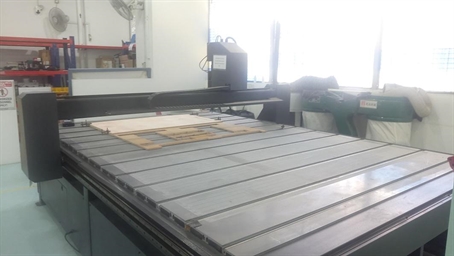
This week’s assignment is to make something big with computer controlled machine. In this case the large CNC milling at SP@Fablab. It is a synvec machine with work area of W2000mmxL3000mmxH300mm. I will use this machine to route some ½ inch plywood to make my pressed fit computer monitor stand capable of holding 2 LCD monitors.
Like other computer controlled machine handling different kind of materials or stocks. A characterisation process has to be performed to determine to optimum setting for good product quality.
Although usually I would use Solidworks CAD tool for my 3D modelling, I have decided to use fusion 360 CAD tool instead. The reason is the latest Fusion 360 comes with a CAM module where tool path can be generated without leaving the software.
Dogbone
To design pressed fit joint on Fusion 360. A “dogbone” add-in has to be installed. The purpose of dogbone is to add circle at all corners of a slot. This is because vertical end mill cutter cannot cut square corner. Here the steps to include dogbone add-in,
1. Download file from the following web link
Video : https://www.youtube.com/watch?v=EM13Dz4Mqnc
File : https://github.com/tapnair/Dogbone
2. Follow the instruction in the same download page.
3. When the dogbone add-in is properly installed, a new icon will appear in the create tab ->
Calibration test pieces design with Fusion360
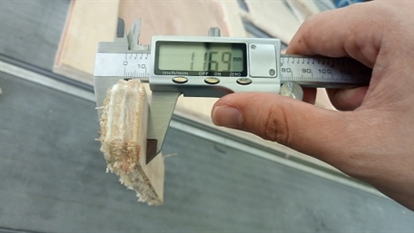
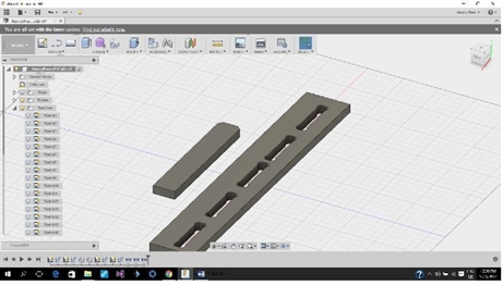
To characterise the machine cutting kerf for pressed fit joint. First measure the thickness of stock, in this case it is 11.69. From past experience I know the kerf required is about 0.3mm, so I created a slot in the centre with width of 11.99mm with 2 smaller slot of 11.89mm and 11.79mm respectively. And larger slot of 12.09mm and 12.19mm respectively. Note that dogbones are added to all corners of the slots->
Generate CAM file for the test pieces
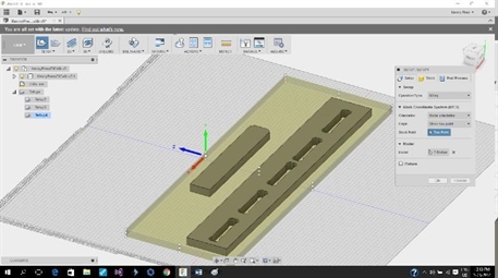
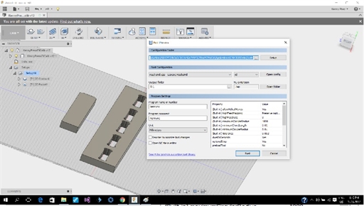
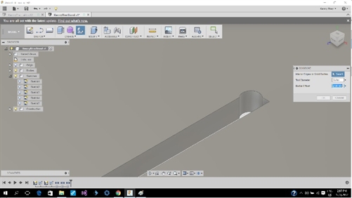
Next go to the CAM module in Fusion 360, create a stock volume that is large enough to hold the test pieces. ->
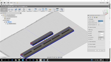
After that, set the tool path, for my case, I am using the 2D contour with tabs added. ->
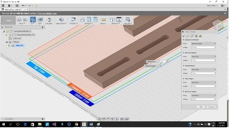
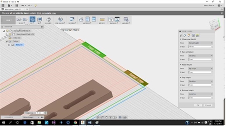
Next is to determine the tool height for free travel and top plane. ->
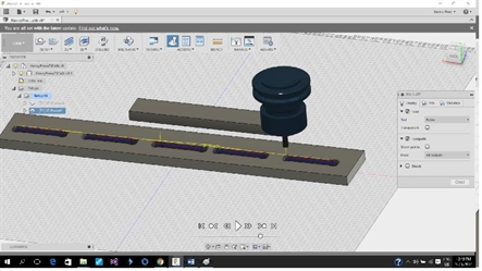
Do a simulation to see tool traveling pattern, ensure that the tool height setting are correct. ->
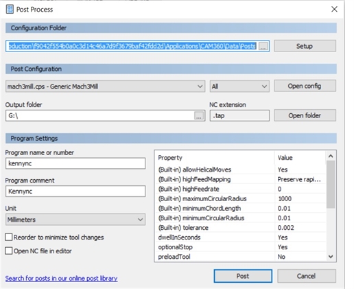
At this stage, we are ready to generate the CAM file. Go to Post processer, select “Mach3mill.cps” as the Post Configuration, enter the Program name or number, click Post button at the bottom and a CAM file is generated. Put the file on a thumb drive and we are ready to work on the CNC machine. ->
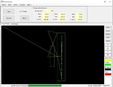
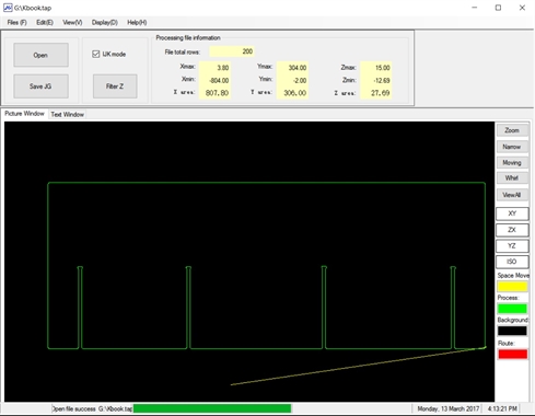
Next to the CNC machine is a PC loaded with a software called “JG”, it converts the “Mach3mill” to a format the CNC machine can understand in .NC format. ->
Tooling
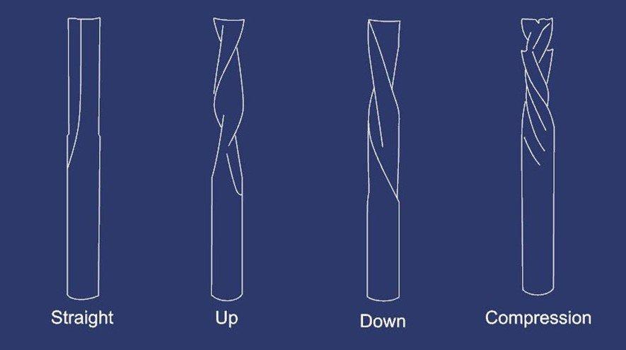
There are 4 main types of flute patterns for router bits, plus many types of specialty bits.
Straight Flute – great all around bit, decent chip removal
Up Spiral – great chip removal, can tear-out the top of thin veneer such as finish grade plywood
Down Spiral – poor chip removal, no tear out, slower feed rate
Compression – combination of up and down spiral, great all around bit, great for plywood or laminated sheet goods.
Toolpaths and Feeds ‘n Speeds
For CNC wood routing or milling, information regarding machine setting can be found from the link:
http://makezine.com/2014/03/21/cnc-routing-basics-toolpaths-and-feeds-n-speeds/
Calculation of feedrate,
Spindle Speed – rotational speed of the cutting tool in revolutions per min
Feed Rate – Surface speed at the center of the rotating tool
Step down – the distance in the z direction per pass that a cutting tool is plunged into the material
Step over – the maximum distance in the x/y direction that a cutting tool will engage with uncut material
Calculating Feeds and Speeds
Below is a formula for calculating feed rate:
ChipLoad x CutterDiameter x NumberOfFlutes x SpindleSpeed = FeedRate
Feed rate vs spindle speed testing
Spindle speed (rpm) 9000 8000 9000
Feed rate (speed ratio) 10% 45% 30%
Result burn mark vibration Good
Machining
Safety is important when working with machine especially an open machine such as this one without an enclosure. besure you know where is the E-stop button.
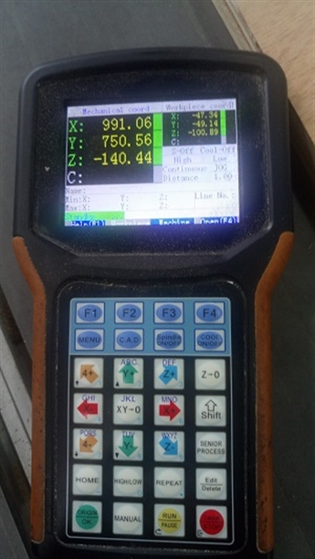
The Synvec CNC milling machine is controlled by a pendent on which a thumb drive can inserted to load the CAM file. Insert the thumb drive on top of the pendent, press F4 to load the desired .NC CAM file. ->
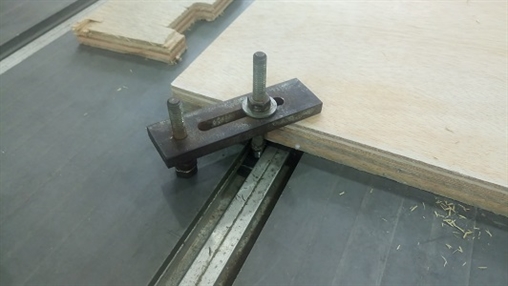
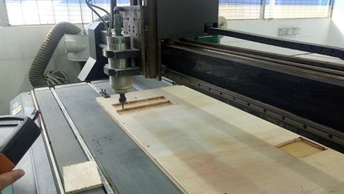
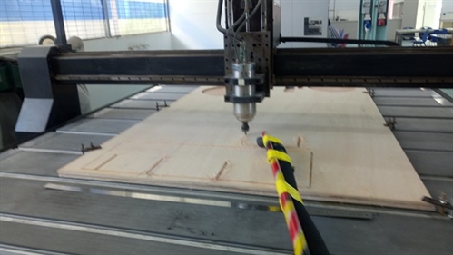
We need to load stock to the machine before cutting, ensure that no one is working on the control pendent, place a 4’x 8’ ½” thick plywood on top of the base wood on the CNC machine table. Clamp the plywood down with T clamps at 4 corners of the plywood. ->
Next is to perform an air cut, move the Z-axis roughly 200mm above the plywood, press “Z-0” to set vertical origin. Press the yellow button “RUN” to run the program. The spindle should start turning and cutting commences. Check that the tool move correctly in the air. ->
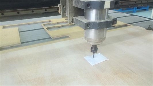
We then need to check the origin of Z-axis(vertical), place a piece of paper on the plywood surface, bring the Z-axis down slowly until it touches the paper. Press “Z-0” to set the origin.->
To start the actual cutting, press “RUN” and cutting begins. ->
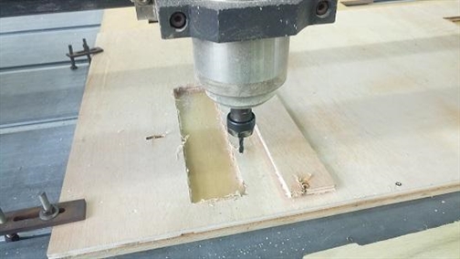
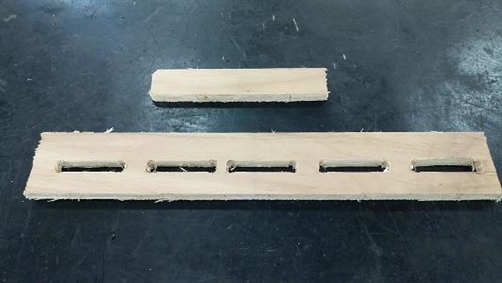
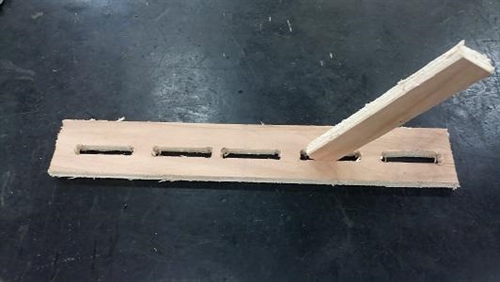
The result of the cutting. We can then test inserting the tab into various slots to determine the best slot width design. In this case, it is the 12.09 mm slot width. ->
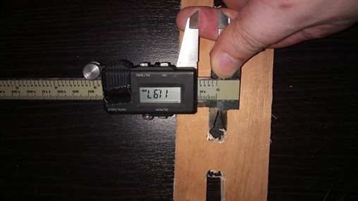
Initial measurement with a vernier caliper was11.97mm, close inspection showed that there was burr on the edges, after sanding the edge (not the surface), the measurement was 12.10mm ->
Safety is important when working with machine especially an open machine such as this one without an enclosure. besure you know where is the E-stop button.
The Synvec CNC milling machine is controlled by a pendent on which a thumb drive can inserted to load the CAM file. Insert the thumb drive on top of the pendent, press F4 to load the desired .NC CAM file. ->
We need to load stock to the machine before cutting, ensure that no one is working on the control pendent, place a 4’x 8’ ½” thick plywood on top of the base wood on the CNC machine table. Clamp the plywood down with T clamps at 4 corners of the plywood. ->
Next is to perform an air cut, move the Z-axis roughly 200mm above the plywood, press “Z-0” to set vertical origin. Press the yellow button “RUN” to run the program. The spindle should start turning and cutting commences. Check that the tool move correctly in the air. ->
We then need to check the origin of Z-axis(vertical), place a piece of paper on the plywood surface, bring the Z-axis down slowly until it touches the paper. Press “Z-0” to set the origin.->
To start the actual cutting, press “RUN” and cutting begins. ->
The result of the cutting. We can then test inserting the tab into various slots to determine the best slot width design. In this case, it is the 12.09 mm slot width. ->
Initial measurement with a vernier caliper was11.97mm, close inspection showed that there was burr on the edges, after sanding the edge (not the surface), the measurement was 12.10mm ->

Making the pressed fit parametric minimalist book shelf
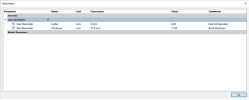
Back to Fusion 360. First create 2 parameters, cutter and thickness. Cutter is the diameter of the end mill used and thickness is the stock thickness. The parameter cutter is used to determine to dogbone size and thickness the width of press fit slot respectively. ->
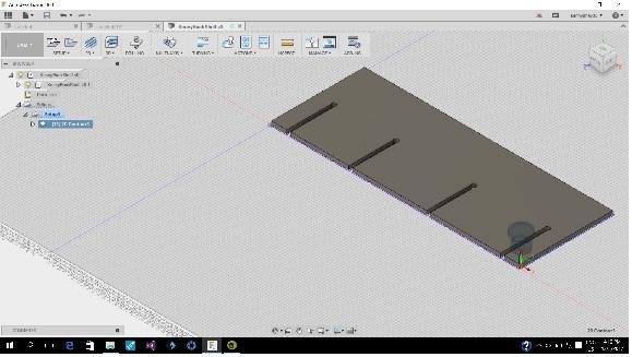
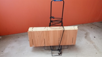
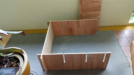
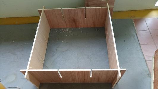
The pressed fit parametric minimalist book shelf only has one single part. It needs six of these part to form a book shelf->
The process of generating CAM file and working on the CNC machine is exactly the same as that on the calibration test pieces. ->
Cutting the pattern on CNC machine ->
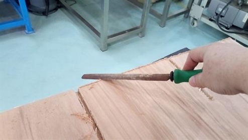
Post CNC cleaning and touching up ->
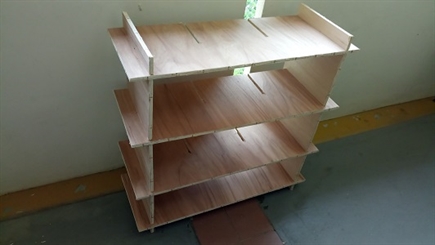
The book shelf :)
Back to Fusion 360. First create 2 parameters, cutter and thickness. Cutter is the diameter of the end mill used and thickness is the stock thickness. The parameter cutter is used to determine to dogbone size and thickness the width of press fit slot respectively. ->
The pressed fit parametric minimalist book shelf only has one single part. It needs six of these part to form a book shelf->
The process of generating CAM file and working on the CNC machine is exactly the same as that on the calibration test pieces. ->
Cutting the pattern on CNC machine ->
Post CNC cleaning and touching up ->
The book shelf :)
Reflection
My favourite tool for 3d modelling is still Solidworks. I like the one part one drawing approach. However, Fusion 360 with its built in CAM feature is a convenient tool for designing model which will be made by computer controlled machining.
Working with wood is quite different from working with metal where material density varies alot.
Although there is an equation for calculating feed rate, it still more of a trial and error affair to get the best result.