Electronics Design
Assignment
-Redraw the echo hello-world board,
add (at least) a button and LED (with current-limiting resistor)
-Check the design rules, make it, and test it
-Extra credit: simulate its operation
-Extra credit: measure its operation
-Redraw the echo hello-world board,
add (at least) a button and LED (with current-limiting resistor)
-Check the design rules, make it, and test it
-Extra credit: simulate its operation
-Extra credit: measure its operation
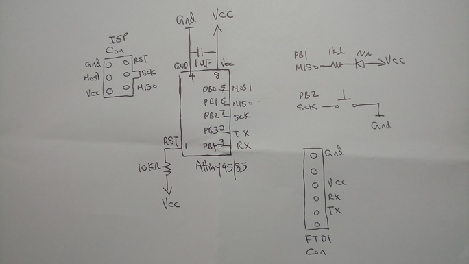
I usually like to start the electronic design on paper rather than diving straight into the EDA tools.
For this assignment, I am going to do a minimalist microconroller board with a button and a LED.
The microcontroller I am going to use is a Attiny 45/85, I find this suitable because only 2 pins are required for the button and LED respectively. Another 2 pins will required for TX and RX for the FTDI connector. to work on the LED and button, the internal clock of suffices so I don't need to install a external crystal.
It is always a good idea to get hold of a copy of the Attiny45/85 datasheet and study it.
http://www.atmel.com/images/atmel-2586-avr-8-bit-microcontroller-attiny25-attiny45-attiny85_datasheet.pdf
Like all microcontroller, Attiny 45/85 requires a VCC (power input) and a GND(ground).
As a good practice, always add a de-coupling capacitor(or noise filtering capacitor) between VCC and GND. In this case I use a 1 uF capacitor.
For Attiny45/85 microcontroller, depends on school of though, most would add a 10K ohm resistor to pull up the RST(reset) pin externally, this is to prevent accdental reset due to pin floating. It is a reliability improvement feature, the system
probably would work without it but I will just add it in for peace of mind.
To program the Attiny45/85, an ISP(In System Programmer) connnector is required. This is a 2x3 header. And to provide USB serial connector to DTE(Data Terminal Equipment) device such as PC, a 6x1 header FTDI connector is required.
A current limiting resistor for LED is must, otherwise power thru the LED is as good as shorting VCC to GND. in this case a 1K ohm. For input I use a button, I will also use the internal pull up resistor, it can be enabled in software using the "Portx" command.
Finally the circuit should look something like the one shown below.
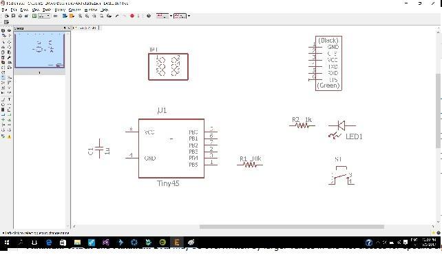
Drawing the board on Eagle EDA tool
With the cirsuit design already worked out. we are now ready to drawing it on the Eagle EDA tool to produce a picture of the PCB(printed circuit bord) layout diagram.
The components required are as follow:
Attiny45/85 microcontroller x1
Resistor 10k x1
Resistor 1k x1
Capacitor 1uf x1
2x3 header x1
1x6 header x1
LED x1
Button x1
At this point,It would be a good idea to decide on the packaging of all the components. I will use SMDs(surface mount devices). I will use the SMD 1206 package for all resistor f, capacitor and LED. SOC8 for the Attiny45/85 microcontroller. Note that there is narrow version the SSU type and a wider version the SU type. the SU type should be used as it more space underneath for tracks. I will also use SMD connector 2x3 and 1x6 headers for ISP and FTDI connectors respectively. The button used is an 4 lead SMD type. you should look through the eagle library and data sheet to acertain the component pad size or foot print.
Next on Eagle is to "Add" all the component in the eagle EDA tool. -->
To find out how to use Eagle EDA tool, check out the following video
https://www.youtube.com/watch?v=1AXwjZoyNno
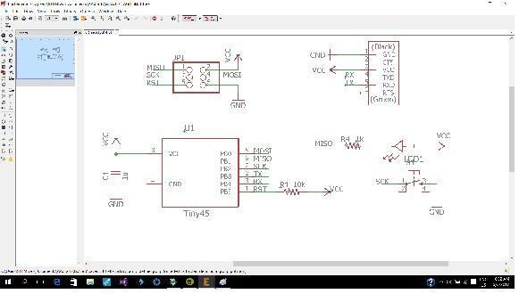
Use the "Line" tool to link all the components together as per the hand drawn design. -->
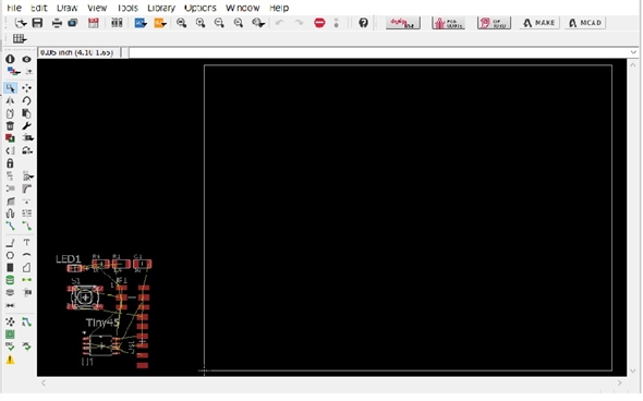
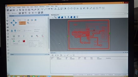
Click on the "generate/switch to baord" icon to prepare to generate the PCB layout diagram. you will see a bunch of compoents link together with thin lines. use "move" tool to move the componet within the board area. -->
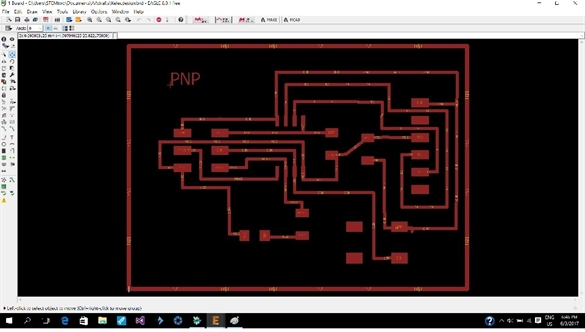
I am going to route the PCB manually,so use "Line" tool mainly to link the componenets together, you should get something like this -->
Feel free to add an initial to the board. I added "PNP"
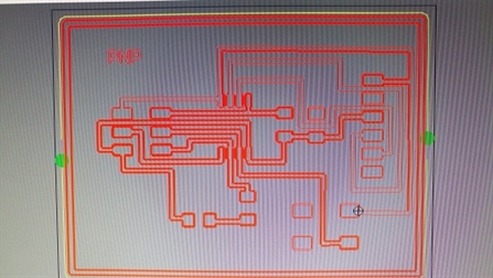
DRC(design rule check)
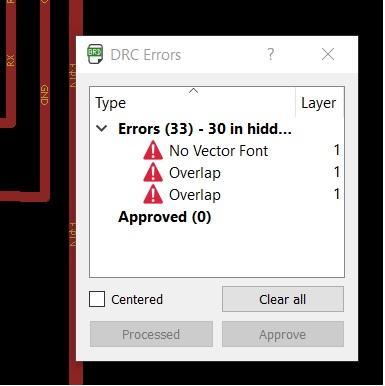
Click on the "DRC" icon, go through all the DRC errors and warning one by one and clear them. -->
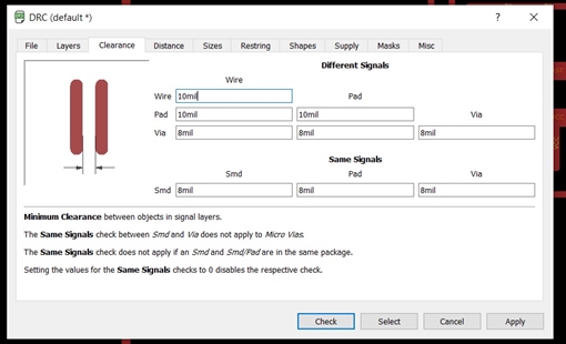
Next go to the DRC window and check the clearance between objects, try to use the bigger clearance possible. It will make the PCB milling process outcome better. I normally use a 12 mil design-->
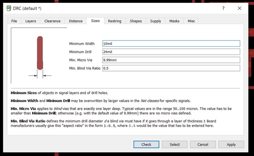
The other important item to check is the minimum size of objects. in this case it would be tracks. If you are using power electronics, you will need to cater for larger object size to cater for bigger current flow to prevent overheating. For my case 12mil is good.-->
Run the DRC again to check that there is no more error. After that, generate the gerber file and your are ready to mill the PCB :).
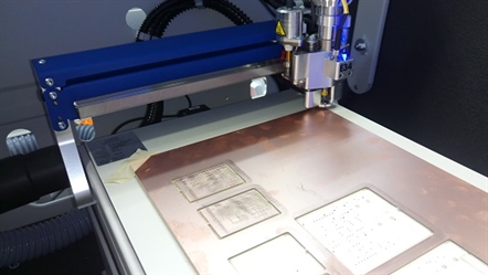
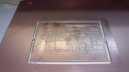
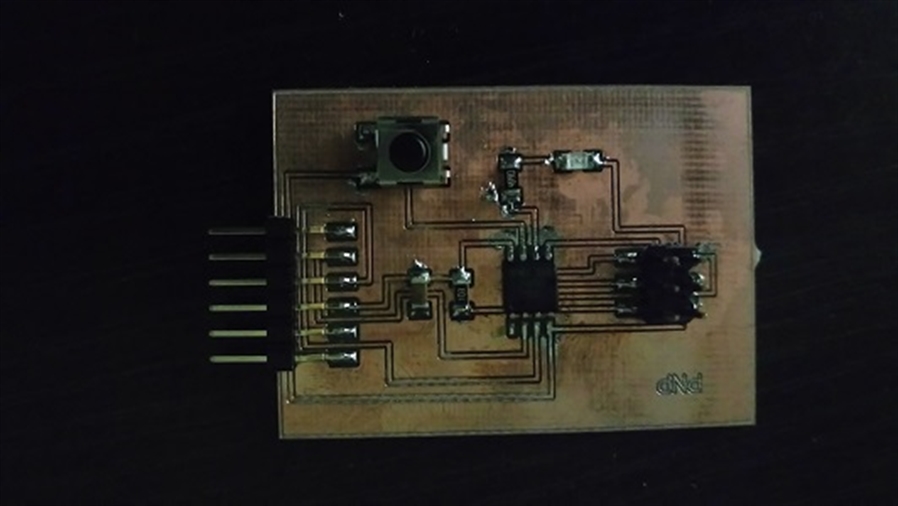
Making the PCB on LKPF PCB router and assemble it.
Click on the "DRC" icon, go through all the DRC errors and warning one by one and clear them. -->
Next go to the DRC window and check the clearance between objects, try to use the bigger clearance possible. It will make the PCB milling process outcome better. I normally use a 12 mil design-->
The other important item to check is the minimum size of objects. in this case it would be tracks. If you are using power electronics, you will need to cater for larger object size to cater for bigger current flow to prevent overheating. For my case 12mil is good.-->
Run the DRC again to check that there is no more error. After that, generate the gerber file and your are ready to mill the PCB :).
Making the PCB on LKPF PCB router and assemble it.
Tesing the PCBA
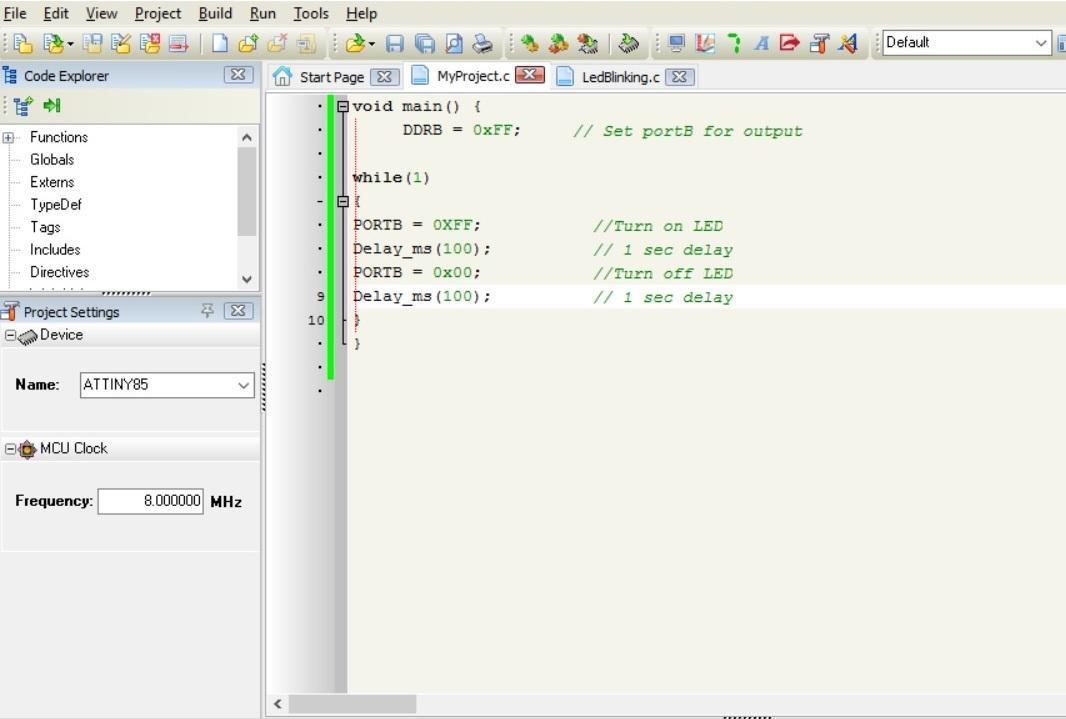
For testig the board, I use a small C program under crosspack on my IMAC to blink the LED
For testig the board, I use a small C program under crosspack on my IMAC to blink the LED
/ main.c
//
// A simple blinky program for ATtiny85
// Connect red LED at pin 6 (PB1)
#include <avr/io.h>
#include <util/delay.h>
int main (void)
{
// set PB1 to be output
DDRB = 0b00000010;
while (1) {
// set PB1 high
PORTB = 0b00000010;
_delay_ms(50);
// set PB1 low
PORTB = 0b00000000;
_delay_ms(50);
}
return 1;
}
Then I flashed the hex file to the PCBA with the command "make install"
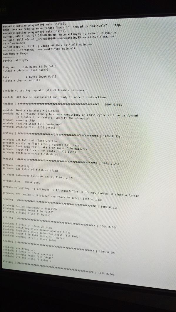
I expected the LED to start blinking but there was nothing. I then checked the LED and current limiting resistor orientations and solder joints. They seemed OK. Never the less, I used soldering iron to touch the joints again to make sure there wasn't any dry joints. Still no blink.
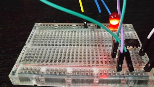
At this point, the problem could be software or handware. If it was software, it would a logic problem because it was able to be compiled without error. I happened to have a DIP Attiny85, so I quickly wired up the circuit on breadboard, flashed the same software and the breadboard version worked, the LED blinked.
At this point, the problem could be software or handware. If it was software, it would a logic problem because it was able to be compiled without error. I happened to have a DIP Attiny85, so I quickly wired up the circuit on breadboard, flashed the same software and the breadboard version worked, the LED blinked.
Measure the operation
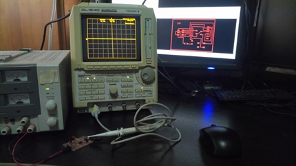
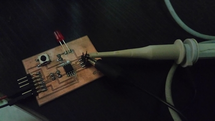
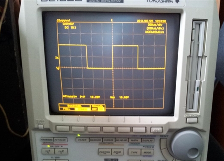
The scope I am using is a yokogawa 150Mhz storage scope. To check the signal from PB1 of Attiny45/85, connect the probe to pin 6 for the signal and GND on the 2X3 header. An oscilloscope is a waveform measuring potential(voltage) change against time. Setting wise, I use a 2.5V per grid as voltage and 200ms for time scale.
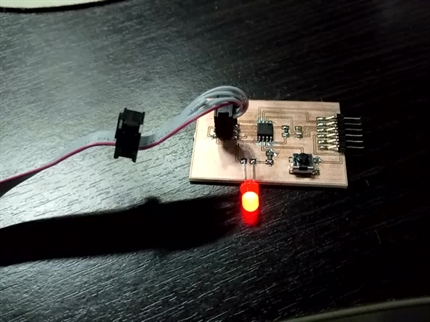
The scope display showed that there was square wave coming out from PB1. At this point I am pretty sure it could be the LED or the resistor giving problem, more likely the LED. However I don't have another SMD 1206 LED at hand and it's Sunday evening, so I decided to replace the SMD LED with a PTH LED. And the board start blinking:)
The scope I am using is a yokogawa 150Mhz storage scope. To check the signal from PB1 of Attiny45/85, connect the probe to pin 6 for the signal and GND on the 2X3 header. An oscilloscope is a waveform measuring potential(voltage) change against time. Setting wise, I use a 2.5V per grid as voltage and 200ms for time scale.
The scope display showed that there was square wave coming out from PB1. At this point I am pretty sure it could be the LED or the resistor giving problem, more likely the LED. However I don't have another SMD 1206 LED at hand and it's Sunday evening, so I decided to replace the SMD LED with a PTH LED. And the board start blinking:)
//The code to turn on the LED when the pushbutton is pressed is shown below.
#include <avr/io.h>
int main(void)
{
while(1)
{
DDRB= 0b00000010; // set PB1 as output and PB2 as input
int pushbutton= PINB2;
if (pushbutton == 0){
PORTB= 0b00000110; // enable pull up resistor in input PB2 and switch on Output PB1
}
else
{
PORTB= 0b00000100; // enable pull up resistor in input PB2 and switch off Output PB1
}
}
}
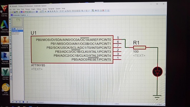
Simulate the operation
Attiny 85 opeation simluation can be done with Proteus Design Suite. This is a simulation tool suggested by our guru Mr Steven Chew at SP@FabLab, so I decided to give it a try, normal, I would use main stream tools like simulink or multisim. Proteus is an EDA tool that includes schematic capture, simulation and PCB layout modules. The software runs on Windows operating system.
To perform microcontroller simulation on an Attiny 85 blinking an LED, create a short program and generate a hex file on compiler such as Mikro C. Then go to Proteus Design Suite, Create an schematic diagram for Attiny 85, a current limiting resistor and a LED. The Proteus Design Suite allow Hex file to be imported for simulation. WIth all that done. a click on the simulation play button and the software will show a LED changing color (Blinking) according to Hex file.
I have written the short code using Mikro C as show below and drawn the schematic diagram using Proteus.
However, I cannot show the blinking LED here because the edition that I have downloaded is a Demo only. The microcontroller simulation is disabled. None the less, you can still see it in the full tutorial for using Mikro C and Proteus to simulate an Attiny microcontroller blinking a LED here.
https://www.youtube.com/watch?v=sbZqWYgWNNU
Reflection
Trouble shooting an electronic circuit requires good understanding of the hardware circuit design and its operation, including the working of the code loaded. It is also important to be familiar with the use of necessary measuring tools such as oscilloscope, multimeter etc...
Simulation is a good way of testing software and hardware design even before the PCB is built and assembled, making development faster and less risky.