3D Scanning and Printing
Assignment
* group project: test the design rules for your printer(s)
* design and 3D print an object (small, few cm) that could not be made subtractively
* 3D scan an object (and optionally print it) (extra credit: make your own scanner)
Group Assignment
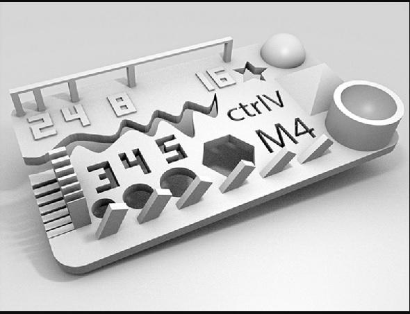
We downloaded the CtrlV M4 Version 2 cablibration piece from thingiverse.com.
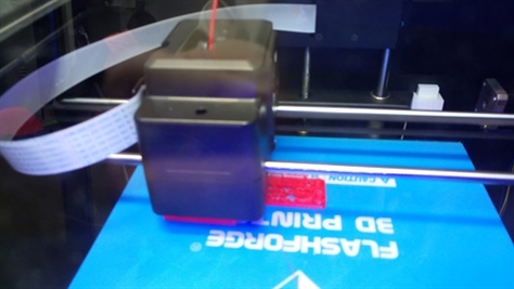
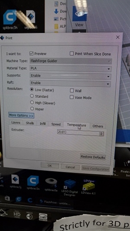
For my part, printing was done on a Flashforge guider 3D printer. This machine can only print PLA material.
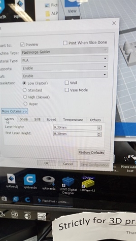
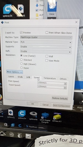
At the advance setting section, there are only 3 parameters you can play with as shown below, they are layer height, print speed and nozzle temperature.
We downloaded the CtrlV M4 Version 2 cablibration piece from thingiverse.com.
For my part, printing was done on a Flashforge guider 3D printer. This machine can only print PLA material.
At the advance setting section, there are only 3 parameters you can play with as shown below, they are layer height, print speed and nozzle temperature.
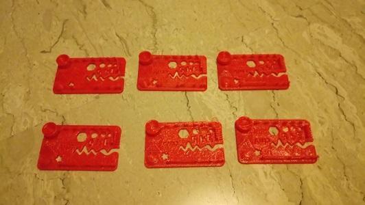
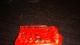
For the samples shown above, print setting from left to right, then next row below
Layer height Print speed Nozzle Temperature Remark
0.3mm 100mm/sec 210 C
0.3mm 80mm/sec 210 C Best overall result
0.2mm 60mm/sec 210 C
0.3mm 100mm/sec 220 C
0.3mm 80mm/sec 220 C
0.2mm 60mm/sec 220 C
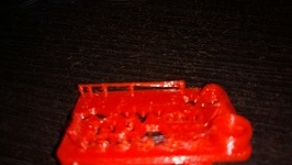
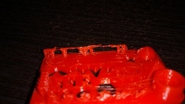
Finding: setting nozzle temperature higher at 220 C is not a good idea, the print quality was bad due to the runiness of the material. For this particular printer in its current condition, layer hight of 0.3mm with print speed of 80mm/sec at 210 C gives a overall better result. The detail print result pictures are shown below.
Layer height Print speed Nozzle Temperature Remark
0.3mm 100mm/sec 210 C
0.3mm 80mm/sec 210 C Best overall result
0.2mm 60mm/sec 210 C
0.3mm 100mm/sec 220 C
0.3mm 80mm/sec 220 C
0.2mm 60mm/sec 220 C
Finding: setting nozzle temperature higher at 220 C is not a good idea, the print quality was bad due to the runiness of the material. For this particular printer in its current condition, layer hight of 0.3mm with print speed of 80mm/sec at 210 C gives a overall better result. The detail print result pictures are shown below.
Tip formation: Worst Better Best
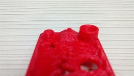
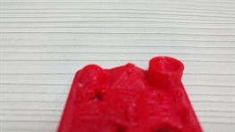
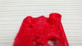
Overhang : Worst Best Better
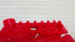
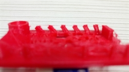
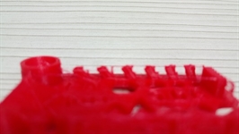
Thin Wall: Worst Better Best
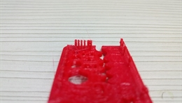
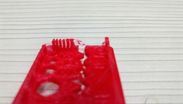
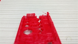
Bridge: Better Best Worst
Hole Dimensional Accuracy; one of more important requirement for my final project is the accuracy of 3D printing, particullarly sizes of holes where fittings are installed. So I also did a hole size calibration.
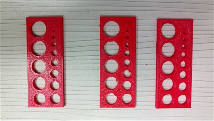
For Samples shown above, print setting from left to right.
Layer height Print speed Nozzle Temperature Remark
0.3mm 100mm/sec 210 C
0.3mm 80mm/sec 210 C
0.2mm 60mm/sec 210 C Slightly better
Measurements were done with a vernier caliper as shown below.
Layer height Print speed Nozzle Temperature Remark
0.3mm 100mm/sec 210 C
0.3mm 80mm/sec 210 C
0.2mm 60mm/sec 210 C Slightly better
Measurements were done with a vernier caliper as shown below.
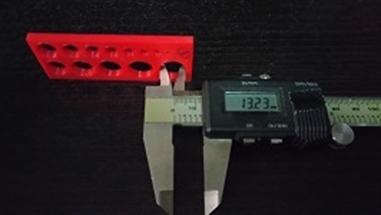
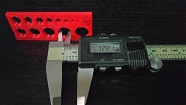
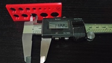
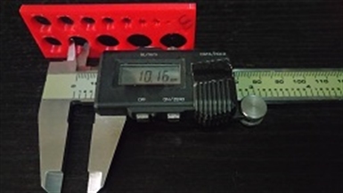
Hole Measurements for samples left to right respectively
Size 10mmm 11mm 12mm 13mm
Measurement 1 10.15mm 11.22mm 12.22mm 13.23mm
Measrurment 2 10.16mm 11.21mm 12.22mm 13.21mm
Measurement 3 10.11mm 11.20mm 12.21mm 13.20mm
Finding: The print results from different settings are not significantly different here. The 0.2 layer hight is marginally better. However, it take a much longer time to print.
Individual Assignment
Design and 3D print an object (small, few cm) that could not be made subtractively
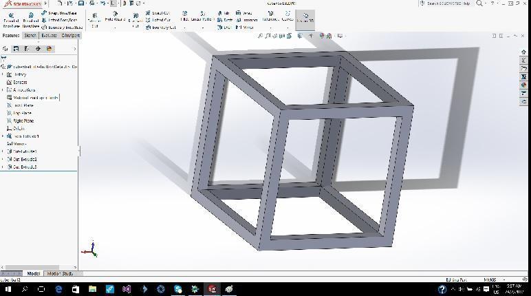
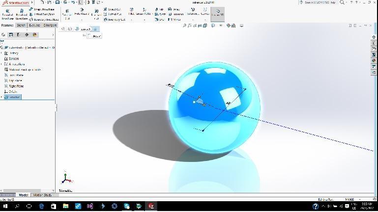
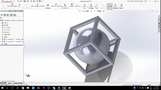
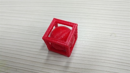
This is a 20mm sphere inside a 20mm cube frame design.
Using Solidworks, first create a 20mm cube frame.
Then a 20mm sphere.
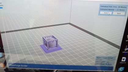
Finally an assembly with the sphere inside the centre of the cube frame.
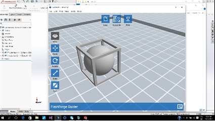
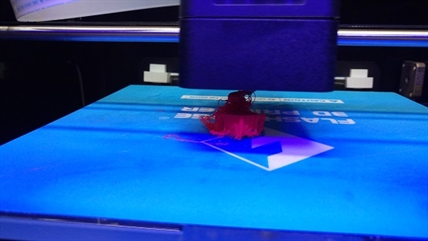
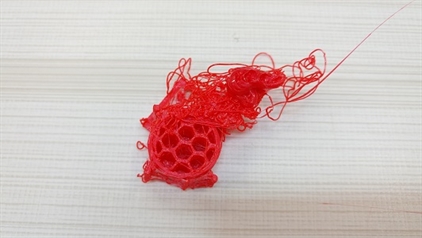
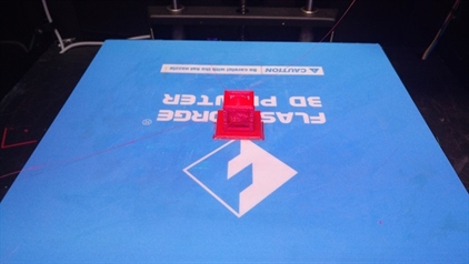
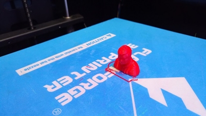
Next is to save as a .stl file for 3D printing. During first printing, the sphere did not stick to the surface and the print was a failure.
After adding a raft to improve the adhereness of the sphere to the surface, it was a success.
Design and 3D print an object (small, few cm) that could not be made subtractively
This is a 20mm sphere inside a 20mm cube frame design.
Using Solidworks, first create a 20mm cube frame.
Then a 20mm sphere.
Finally an assembly with the sphere inside the centre of the cube frame.
Next is to save as a .stl file for 3D printing. During first printing, the sphere did not stick to the surface and the print was a failure.
After adding a raft to improve the adhereness of the sphere to the surface, it was a success.
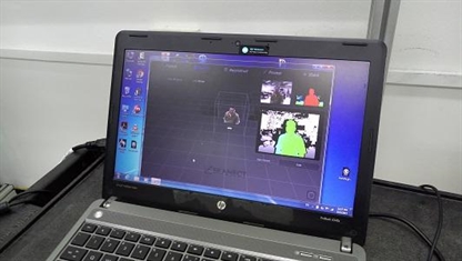
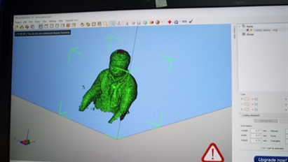
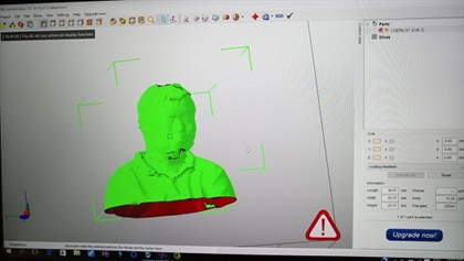
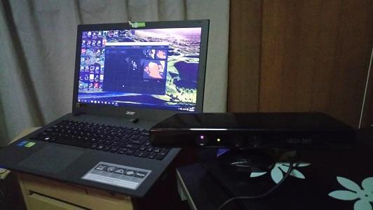
3D Scanning using Microsoft Kinect Sensor at SP@FabLab
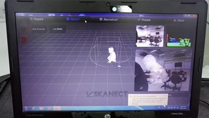
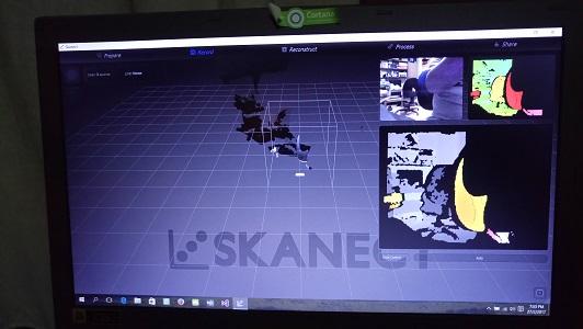
This is a scanner using a depth image sensor(microsoft kinect). follow the steps shown on the display to get a body scan.
1. Prepare, set the body as scan area
2. Record, the actual scanning process
3. Reconstruct and Process, touch up the scan mesh.
4. Share, export and save as .stl file.
5. Post repair and croping can be done with Netfabb software.
6. Print the part.
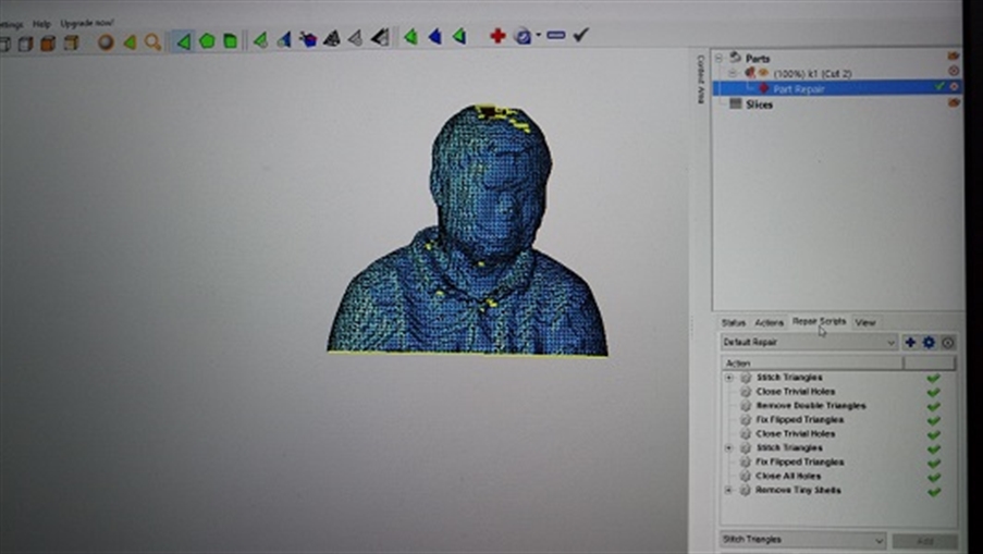
Post processing:
Netfab is a software now under Autodesk that can be used to repair broken mesh data after scanning. it can also be used to remove and crop unwanted section of the mesh, making the stl file ready for 3D printing.
Netfab is a software now under Autodesk that can be used to repair broken mesh data after scanning. it can also be used to remove and crop unwanted section of the mesh, making the stl file ready for 3D printing.
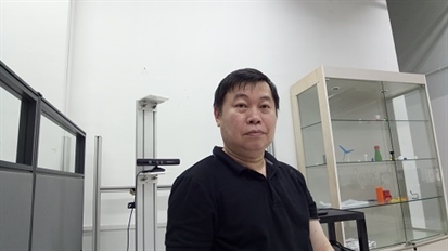
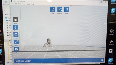
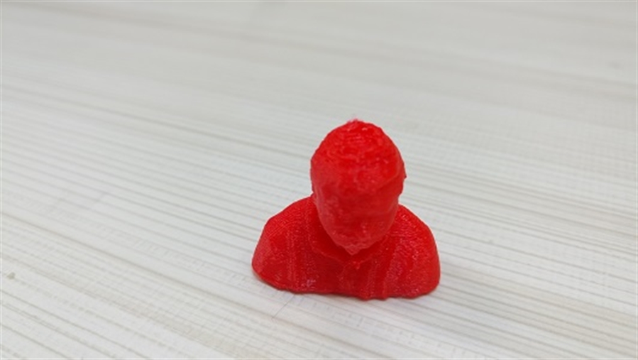
3D printing of myself :)
Bonus
Making your own scanner.
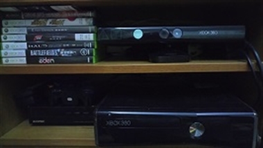
If you have a Xbox 360 game console and Kinect sensor, then you are in luck, it can be turned into a 3D scanner quite easily as shown previously,
Here are what you will need:
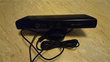
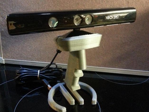
-Miscrosoft Kinect sensor
The Kinect contains three vital pieces that work together to detect your motion and create your physical image on the screen: an RGB color VGA video camera, a depth sensor, and a multi-array microphone.
The camera detects the red, green, and blue color components as well as body-type and facial features. It has a pixel resolution of 640x480 and a frame rate of 30 fps. This helps in facial recognition and body recognition.
The depth sensor contains a monochrome CMOS sensor and infrared projector that help create the 3D imagery throughout the room. It also measures the distance of each point of the player's body by transmitting invisible near-infrared light and measuring its "time of flight" after it reflects off the objects.
You can also buy a refurbished kinect for US$29.99 from amazon
https://www.amazon.com/Microsoft-XBOX-Kinect-Sensor-Certified-Refurbished/dp/B005GA1H4C/ref=pd_bxgy_63_2?_encoding=UTF8&refRID=NCCWFMPVS4841NKVV7GB&th=1
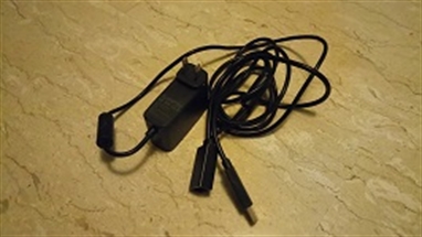
-Power adapter for Kinect
12V DC adaptor, Kinect runs on 12VDV on 5V, you can either do some clever wiring from the xbox 360 console or get the adepter shown on the right from amason, it is US$3.99.
https://www.amazon.com/Adapter-Kinect-360-HandHelditems-Sketch-Universal/dp/B005EIXVAE
-PC
CPU Reconstruction: 2 GB RAM, Quad core processor.
GPU Reconstruction: 2 GB RAM, Intel Core 2, Cuda 2.0 compatible graphics card, with 1 Gb of memory
Recommended PC: Windows 7 or later (64 bits), Intel i7, 4 GB RAM, NVIDIA GTX 560 or higher.
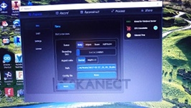
-Scanner software from Skanect
Steps:
1. Download and install Microsoft Kinect SDK software.
2. Download and install Skanect software
http://skanect.occipital.com/
3. Connect Power adapter to Kinect, then connect Kinect to a USB port of PC. Launch Skanect software and the scanner is ready to be used.
Making your own scanner.
If you have a Xbox 360 game console and Kinect sensor, then you are in luck, it can be turned into a 3D scanner quite easily as shown previously,
Here are what you will need:
-Miscrosoft Kinect sensor
The Kinect contains three vital pieces that work together to detect your motion and create your physical image on the screen: an RGB color VGA video camera, a depth sensor, and a multi-array microphone.
The camera detects the red, green, and blue color components as well as body-type and facial features. It has a pixel resolution of 640x480 and a frame rate of 30 fps. This helps in facial recognition and body recognition.
The depth sensor contains a monochrome CMOS sensor and infrared projector that help create the 3D imagery throughout the room. It also measures the distance of each point of the player's body by transmitting invisible near-infrared light and measuring its "time of flight" after it reflects off the objects.
You can also buy a refurbished kinect for US$29.99 from amazon
https://www.amazon.com/Microsoft-XBOX-Kinect-Sensor-Certified-Refurbished/dp/B005GA1H4C/ref=pd_bxgy_63_2?_encoding=UTF8&refRID=NCCWFMPVS4841NKVV7GB&th=1
-Power adapter for Kinect
12V DC adaptor, Kinect runs on 12VDV on 5V, you can either do some clever wiring from the xbox 360 console or get the adepter shown on the right from amason, it is US$3.99.
https://www.amazon.com/Adapter-Kinect-360-HandHelditems-Sketch-Universal/dp/B005EIXVAE
-PC
CPU Reconstruction: 2 GB RAM, Quad core processor.
GPU Reconstruction: 2 GB RAM, Intel Core 2, Cuda 2.0 compatible graphics card, with 1 Gb of memory
Recommended PC: Windows 7 or later (64 bits), Intel i7, 4 GB RAM, NVIDIA GTX 560 or higher.
-Scanner software from Skanect
Steps:
1. Download and install Microsoft Kinect SDK software.
2. Download and install Skanect software
http://skanect.occipital.com/
3. Connect Power adapter to Kinect, then connect Kinect to a USB port of PC. Launch Skanect software and the scanner is ready to be used.

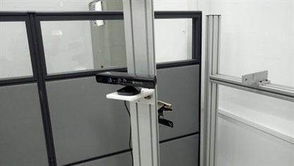
Optionally, you can go to thingiverse(as shown below) or design and print your own kinect sensor holder.
Reflection
There are many 3D printing technologies on the market, only one (Fused deposition modelling) is used in this exercise. Additive manufacturing technology offers the advantage of saving material and the ability to print complex design. Similarly, there are many 3D scanning technologies existing. These are effective and quick ways to capture structural design
There are many 3D printing technologies on the market, only one (Fused deposition modelling) is used in this exercise. Additive manufacturing technology offers the advantage of saving material and the ability to print complex design. Similarly, there are many 3D scanning technologies existing. These are effective and quick ways to capture structural design