Interface and application programming
Assignment
Write an application that interfaces with an input &/or output device that you made,
comparing as many tool options as possible
Write an application that interfaces with an input &/or output device that you made,
comparing as many tool options as possible
Application that interface to MPU 6050 module
This is a test jig to see if a MPU6050 connected to a DIY Atmega328P is working properly. To do that. An real time aviation horizon display shows the data graphically by tilting the scale bar and horizon line.
This is a test jig to see if a MPU6050 connected to a DIY Atmega328P is working properly. To do that. An real time aviation horizon display shows the data graphically by tilting the scale bar and horizon line.
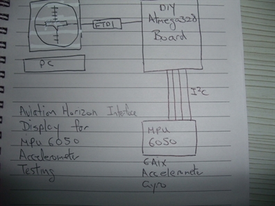
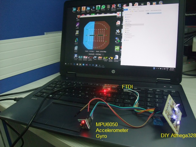
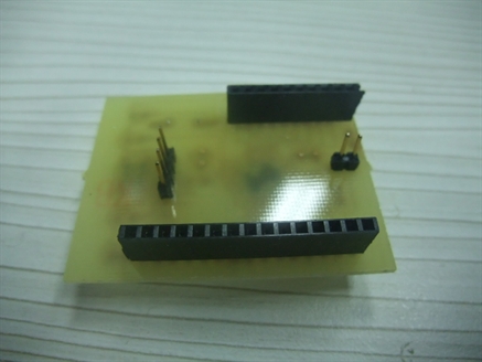
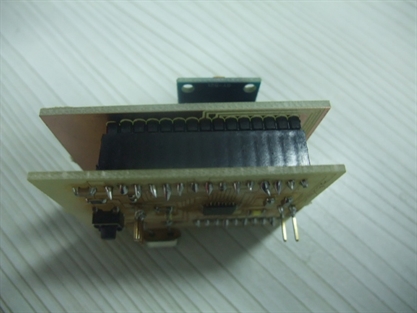
Hardware includes a DIY Atmega328P based board interfaces to PC via a FTDI cable. if everything works, I will make a DIY shield piggybacked on the Atmega328P board. The shield will houses the MPU-6050 module.
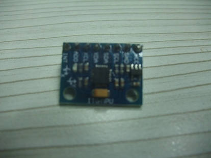
The MPU-6050 sensor contains a accelerometer and a gyro in a single chip. It is very accurate, as it contains 16-bits analog to digital conversion hardware for each channel. Therefor it captures the x, y, and z channel at the same time. The sensor uses the I2C-bus to interface with the Atmega 328 board.
The MPU-6050 sensor contains a accelerometer and a gyro in a single chip. It is very accurate, as it contains 16-bits analog to digital conversion hardware for each channel. Therefor it captures the x, y, and z channel at the same time. The sensor uses the I2C-bus to interface with the Atmega 328 board.
The interface application is developed with Processing. Processing is a flexible software sketchbook and a language for learning how to code within the context of the visual arts. Since 2001, Processing has promoted software literacy within the visual arts and visual literacy within technology. There are tens of thousands of students, artists, designers, researchers, and hobbyists who use Processing for learning and prototyping.
More on how to use processing can be found at:
https://processing.org/
More on how to use processing can be found at:
https://processing.org/
How the application works
On the left, you can see the main part of the program.
First the setup() setups the serial communication with the Atmega328 board at 15200 bps.
In processing, draw() is the main program loop. There are 4 main functions to decode the information from MPU6050 via Atmega328 boards.
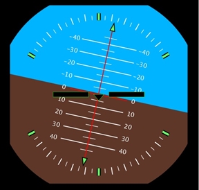
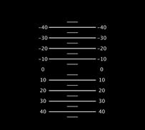
First is Horizon(), this function paints the main background and displays the angular scale as shown below.
Next is the PitchScale() which displays the ladder pitch diagram as shown below.
Axis() is the function that displays the row graphical information.
And finally, the plane() function display the static horizontal wing.
On the left, you can see the main part of the program.
First the setup() setups the serial communication with the Atmega328 board at 15200 bps.
In processing, draw() is the main program loop. There are 4 main functions to decode the information from MPU6050 via Atmega328 boards.
First is Horizon(), this function paints the main background and displays the angular scale as shown below.
Next is the PitchScale() which displays the ladder pitch diagram as shown below.
Axis() is the function that displays the row graphical information.
And finally, the plane() function display the static horizontal wing.
Serial port;
float Phi; //Dimensional axis
float Theta;
float Psi;
void setup()
{
size(700, 700); //was 1400, 700
rectMode(CENTER);
smooth();
// strokeCap(SQUARE);//Optional
println(Serial.list()); //Shows your connected serial ports
port = new Serial(this, Serial.list()[0], 115200);
//Up there you should select port which arduino connected and same baud rate.
port.bufferUntil(' ');
}
void draw()
{
background(0);
translate(W/4, H/2.1);
MakeAnglesDependentOnMPU6050();
// Horizon();
// rotate(-Bank);
// PitchScale();
// Axis();
// rotate(Bank);
// Borders();
Plane();
}
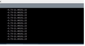
void serialEvent(Serial port) //Reading the datas by Processing.
{
String input = port.readStringUntil(' ');
if(input != null){
input = trim(input);
String[] values = split(input, " ");
if(values.length == 3){
float phi = float(values[0]);
float theta = float(values[1]);
float psi = float(values[2]);
print(phi);
print(theta);
println(psi);
Phi = phi;
Theta = theta;
Psi = psi;
}
}
}
float Phi; //Dimensional axis
float Theta;
float Psi;
void setup()
{
size(700, 700); //was 1400, 700
rectMode(CENTER);
smooth();
// strokeCap(SQUARE);//Optional
println(Serial.list()); //Shows your connected serial ports
port = new Serial(this, Serial.list()[0], 115200);
//Up there you should select port which arduino connected and same baud rate.
port.bufferUntil(' ');
}
void draw()
{
background(0);
translate(W/4, H/2.1);
MakeAnglesDependentOnMPU6050();
// Horizon();
// rotate(-Bank);
// PitchScale();
// Axis();
// rotate(Bank);
// Borders();
Plane();
}
void serialEvent(Serial port) //Reading the datas by Processing.
{
String input = port.readStringUntil(' ');
if(input != null){
input = trim(input);
String[] values = split(input, " ");
if(values.length == 3){
float phi = float(values[0]);
float theta = float(values[1]);
float psi = float(values[2]);
print(phi);
print(theta);
println(psi);
Phi = phi;
Theta = theta;
Psi = psi;
}
}
}


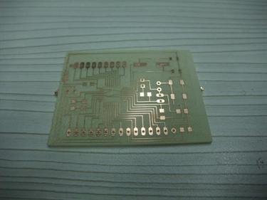
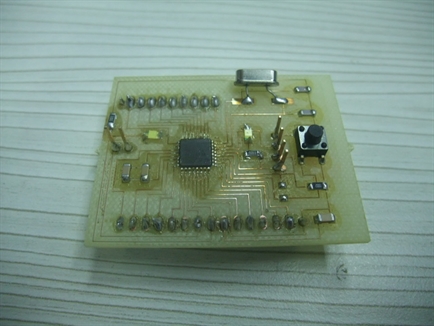
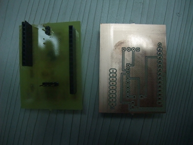
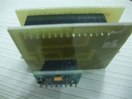
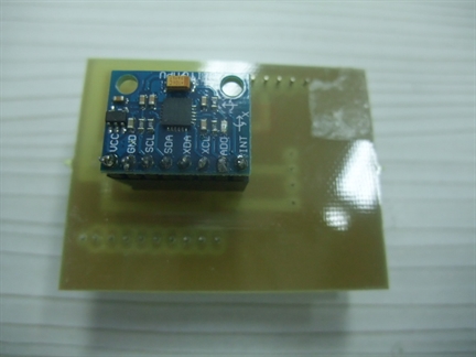
After making sure everything is working, I made an interface board for the MPU6050.
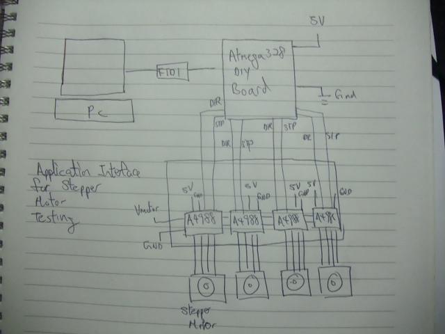
Application interface for stepper motor testing
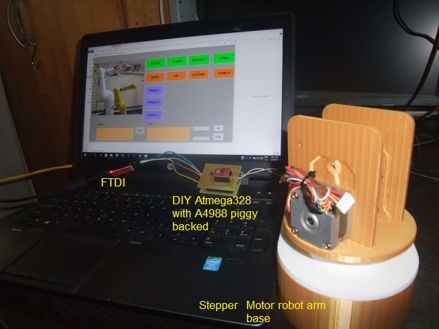
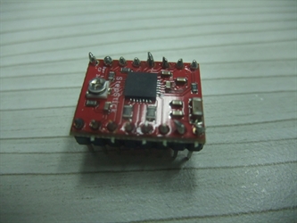
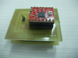
This application is developed using .Net development tool. The hardware include a DIY Atmega328P based board interfaces to a PC via FTDI cable. There is a DIY shield piggy backed on the Atmega328P board. The shield houses an A4988 stepper driver module.
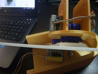
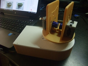
The application will be designed to run four stepper motors, but for testing, I will use one stepper driver to control the robot arm base in my final project using D5 and D6 dir direction and step control respectively.
If everything works, I will expand the piggy back expansion board to include four A4988 drivers using D7,D8,D9,D10,D11,D12 as control lines for another 3 steppers..
This application is developed using .Net development tool. The hardware include a DIY Atmega328P based board interfaces to a PC via FTDI cable. There is a DIY shield piggy backed on the Atmega328P board. The shield houses an A4988 stepper driver module.
The application will be designed to run four stepper motors, but for testing, I will use one stepper driver to control the robot arm base in my final project using D5 and D6 dir direction and step control respectively.
If everything works, I will expand the piggy back expansion board to include four A4988 drivers using D7,D8,D9,D10,D11,D12 as control lines for another 3 steppers..
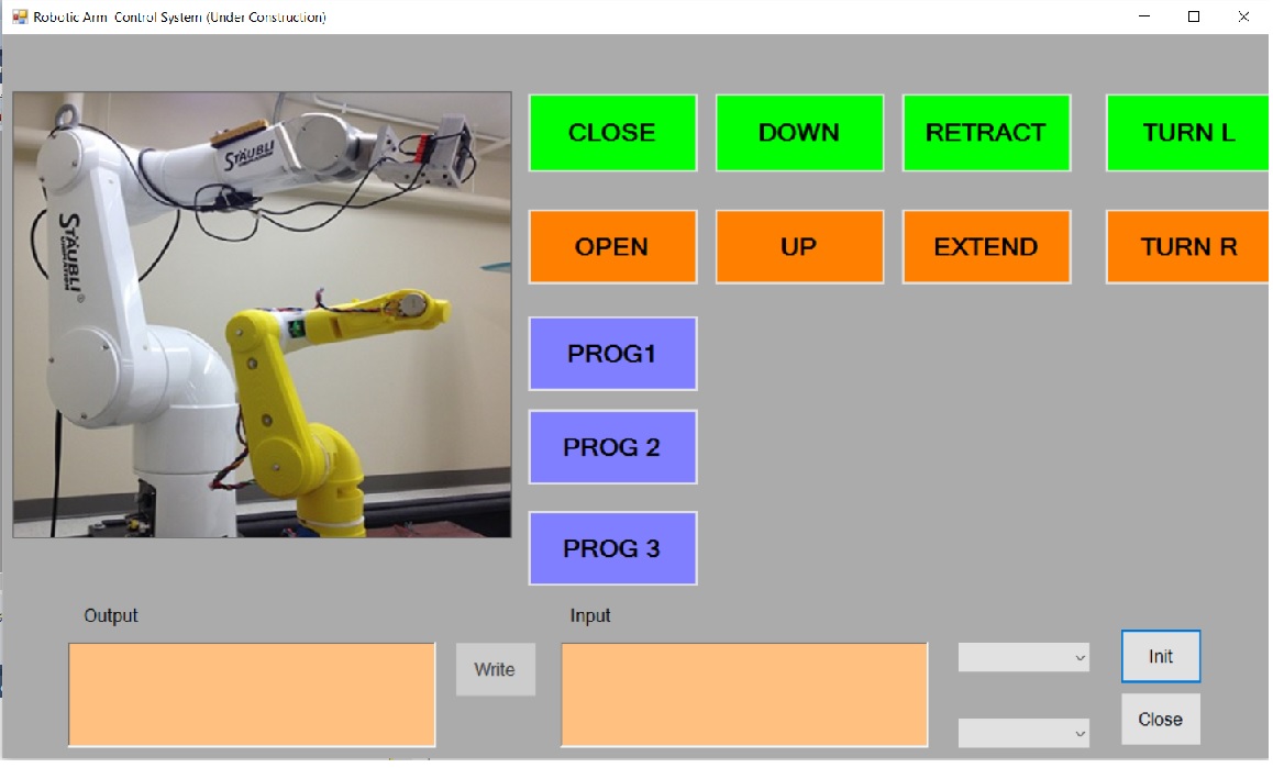
User interface
The user interface includes a number of buttons to move each stepper motor joints.
There are three Buttons, PROG1 to PROG3 to initiate a predefined sequence of movements.
And the bottom. There are buttons and displays to activate and monitor serial communication between the application interface and Atmega328 board.
How the program works
First the application interface establish a serial link with the Atmega328 board at 9600 bps.
When a button is pressed, for example the “UP”, the UI will send a corresponded character to Atmega328 board, which in turn send direction and step pules to the A4988 stepper driver to move the stepper motor.
PROG1 to PROG3 like other buttons, sends a unique character to the Atmega328 board, but this time it triggers a hard coded routine to perform a series of movement involving more than one stepper motors.
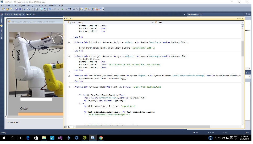
Imports System
Imports System.Threading
Imports System.IO.Ports
Imports System.ComponentModel
Public Class Form1
'------------------------------------------------
Dim myPort As Array
Delegate Sub SetTextCallback(ByVal [text] As String) 'Added to prevent threading errors during receiveing of data
'------------------------------------------------
Private Sub Form1_Load(sender As System.Object, e As System.EventArgs) Handles MyBase.Load
myPort = IO.Ports.SerialPort.GetPortNames()
ComboBox1.Items.AddRange(myPort)
Button2.Enabled = False
End Sub
'------------------------------------------------
Private Sub ComboBox1_Click(sender As System.Object, e As System.EventArgs) Handles ComboBox1.Click
End Sub
'------------------------------------------------
Private Sub Button1_Click(sender As System.Object, e As System.EventArgs) Handles Button1.Click
SerialPort1.PortName = ComboBox1.Text
SerialPort1.BaudRate = ComboBox2.Text
SerialPort1.Open()
Button1.Enabled = False
Button2.Enabled = True
Button4.Enabled = True
End Sub
'------------------------------------------------
Private Sub Button2_Click(sender As System.Object, e As System.EventArgs) Handles Button2.Click
SerialPort1.Write(RichTextBox1.Text & vbCr) 'concatenate with
End Sub
Private Sub Button4_Click(sender As System.Object, e As System.EventArgs) Handles Button4.Click
SerialPort1.Close()
Button1.Enabled = True
Button2.Enabled = False 'This Butoon is not in used for this section
Button4.Enabled = False
End Sub
Private Sub SerialPort1_DataReceived(sender As System.Object, e As System.IO.Ports.SerialDataReceivedEventArgs) Handles SerialPort1.DataReceived
ReceivedText(SerialPort1.ReadExisting())
End Sub
Private Sub ReceivedText(ByVal [text] As String) 'input from ReadExisting
If Me.RichTextBox2.InvokeRequired Then
Dim x As New SetTextCallback(AddressOf ReceivedText)
Me.Invoke(x, New Object() {(text)})
Else
Me.RichTextBox2.Text &= [text] 'append text
Me.RichTextBox2.SelectionStart = Me.RichTextBox2.Text.Length
'' Me.RichTextBox2.SelectionLength = 0
' Me.RichTextBox2.Text &= [text] 'append text
Me.TextBox1.Text = text.ToString
'' Me.Label3.Text = " ' this is a control system for moving the arm up and down
'' Me.Label3.Text &= [text]
End If
End Sub
Private Sub Button3_Click(ByVal sender As System.Object, ByVal e As System.EventArgs) Handles Button3.Click
'' SerialPort1.Open()
SerialPort1.Write("1")
'' SerialPort1.Close()
End Sub
Private Sub Button5_Click(ByVal sender As System.Object, ByVal e As System.EventArgs) Handles Button5.Click
'' SerialPort1.Open()
SerialPort1.Write("0")
'' SerialPort1.Close()
End Sub
Private Sub Button7_Click(ByVal sender As System.Object, ByVal e As System.EventArgs) Handles Button7.Click
'' SerialPort1.Open()
SerialPort1.Write("2")
'' SerialPort1.Close()
End Sub
Private Sub Button8_Click(ByVal sender As System.Object, ByVal e As System.EventArgs) Handles Button8.Click
'' SerialPort1.Open()
SerialPort1.Write("3")
'' SerialPort1.Close()
End Sub
Private Sub Button9_Click(ByVal sender As System.Object, ByVal e As System.EventArgs) Handles Button9.Click
'' SerialPort1.Open()
SerialPort1.Write("4")
'' SerialPort1.Close()
End Sub
Private Sub Button10_Click(ByVal sender As System.Object, ByVal e As System.EventArgs) Handles Button10.Click
'' SerialPort1.Open()
SerialPort1.Write("5")
'' SerialPort1.Close()
End Sub
Private Sub Button11_Click(ByVal sender As System.Object, ByVal e As System.EventArgs) Handles Button11.Click
'' SerialPort1.Open()
SerialPort1.Write("0")
Threading.Thread.Sleep(1000)
SerialPort1.Write("1")
Threading.Thread.Sleep(1000)
SerialPort1.Write("2")
Threading.Thread.Sleep(1000)
SerialPort1.Write("3")
Threading.Thread.Sleep(1000)
SerialPort1.Write("4")
Threading.Thread.Sleep(1000)
SerialPort1.Write("5")
'' SerialPort1.Close()
End Sub
Private Sub Button12_Click(ByVal sender As System.Object, ByVal e As System.EventArgs) Handles Button12.Click
'' SerialPort1.Open()
SerialPort1.Write("2")
Threading.Thread.Sleep(1000)
SerialPort1.Write("3")
Threading.Thread.Sleep(1000)
SerialPort1.Write("4")
Threading.Thread.Sleep(1000)
SerialPort1.Write("5") '' central system is not available for command and control
Threading.Thread.Sleep(1000)
SerialPort1.Write("4")
Threading.Thread.Sleep(1000)
SerialPort1.Write("5")
SerialPort1.Write("0")
Threading.Thread.Sleep(1000)
SerialPort1.Write("1")
Threading.Thread.Sleep(1000)
'' SerialPort1.Close()
End Sub
Private Sub Button13_Click(ByVal sender As System.Object, ByVal e As System.EventArgs) Handles Button13.Click
'' SerialPort1.Open()
Threading.Thread.Sleep(1000)
SerialPort1.Write("4")
Threading.Thread.Sleep(1000)
SerialPort1.Write("5")
Threading.Thread.Sleep(1000)
SerialPort1.Write("4")
Threading.Thread.Sleep(1000) '' control for this section is not available for sytem review
SerialPort1.Write("5")
Threading.Thread.Sleep(1000)
SerialPort1.Write("2")
Threading.Thread.Sleep(1000)
SerialPort1.Write("3")
Threading.Thread.Sleep(1000)
SerialPort1.Write("0")
Threading.Thread.Sleep(1000)
SerialPort1.Write("1")
Threading.Thread.Sleep(1000)
'' SerialPort1.Close()
End Sub
Private Sub Button15_Click(ByVal sender As System.Object, ByVal e As System.EventArgs) Handles Button15.Click
'' SerialPort1.Open()
SerialPort1.Write("6")
'' SerialPort1.Close()
End Sub
Private Sub Button14_Click(ByVal sender As System.Object, ByVal e As System.EventArgs) Handles Button14.Click
'' SerialPort1.Open()
SerialPort1.Write("7")
'' SerialPort1.Close()
End Sub
End Class
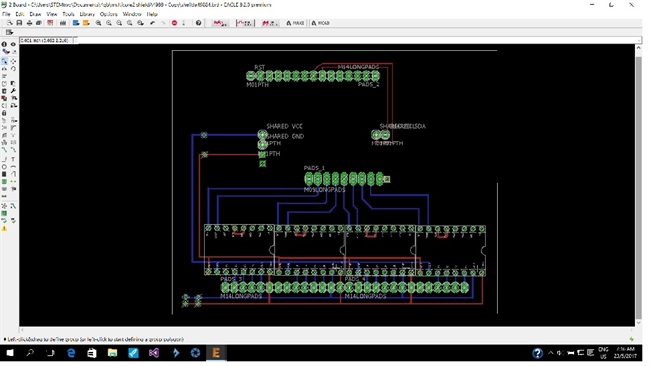
Follow up works
After successfully tested a single stepper motor, it is time to add more motors to the circuitry for my final project.
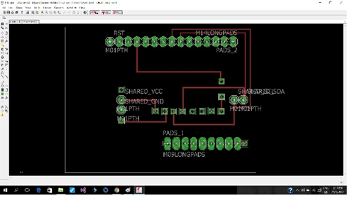
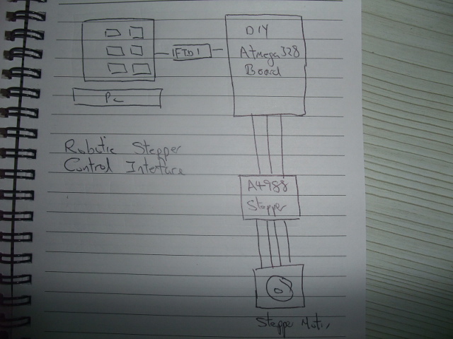
There are 2 possible approaches. I can either use one Atmega328 with one A4988 and serial link them together, much like gestalt node, or control four stepper motors with one Atmega328 board as shown below. The advantage of later design is that it would be possible to use existing GBRL control software.
After successfully tested a single stepper motor, it is time to add more motors to the circuitry for my final project.
There are 2 possible approaches. I can either use one Atmega328 with one A4988 and serial link them together, much like gestalt node, or control four stepper motors with one Atmega328 board as shown below. The advantage of later design is that it would be possible to use existing GBRL control software.
Reflection
There are many software tools available for developing interface application. But generally for mission critical application (ie must finish a certain task within a specific time) Compiled language such as C is preferred over interpreter language such as Basic.
So for Industrial project, I would use C language and some time for critical application, assembly language. For casual project and rapid prototyping, I would use .Net viusal basic, Python or Processing.
Often writing interface application is the final step of system development where final system integration is carried out. At this stage all sub system need to debuged to be fully functional. This is why the application developer is often the final system integrator.