Networking and communications
Assignment
Design and build a wired &/or wireless network connecting at least two processors.
For this week assignment, I will make a wired network and a wireless network. The wired network will consist of two Atmega 328 boards . The wireless network I will use a Atmega328 boardwith a Bluetooth interface to PC.
If time allows, I will also try out the Attiny 45 version of serial network.
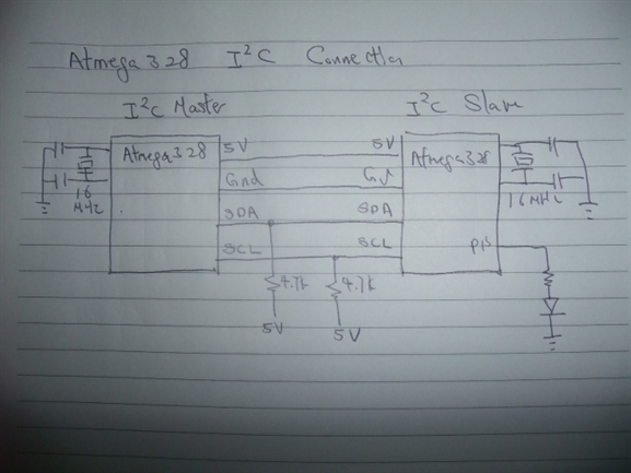
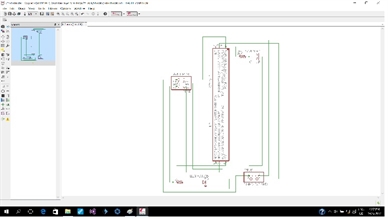
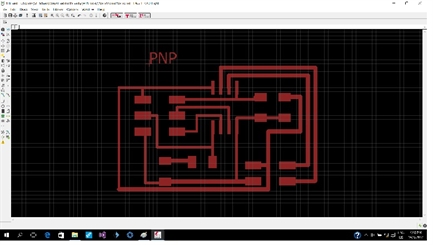
Wired 12C network
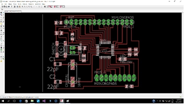
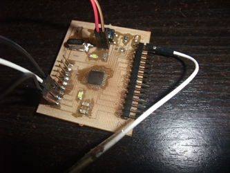
I used satshakit’s design with a small change. The modification is required because I don’t have a SMD 16Mhz crystal, So I add 2 through holes to use the PTH version of crystal that I have.
I used satshakit’s design with a small change. The modification is required because I don’t have a SMD 16Mhz crystal, So I add 2 through holes to use the PTH version of crystal that I have.
// I2C Master
// Original by Cornel Amariei
// Modified by Kenny Phay for
// Include the required Wire library for I2C
#include <Wire.h>
int x = 0;
void setup() {
// Start the I2C Bus as Master
Wire.begin();
}
void loop() {
Wire.beginTransmission(9); // transmit to device #9
Wire.write(x); // sends x
Wire.endTransmission(); // stop transmitting
x++; // Increment x
if (x > 5) x = 0; // `reset x once it gets 6
delay(500);
}
// I2C Slave
// Original by Cornel Amariei
// Modified by : Kenny Phay 10 May 2017
// Include the required Wire library for I2C
#include <Wire.h>
int LED = 13;
int x = 0;
void setup() {
// Define the LED pin as Output
pinMode (LED, OUTPUT);
// Start the I2C Bus as Slave on address 9
Wire.begin(9);
// Attach a function to trigger when something is received.
Wire.onReceive(receiveEvent);
}
void receiveEvent(int bytes) {
x = Wire.read(); // read one character from the I2C
}
void loop() {
//If value received is 0 blink LED for 200 ms
if (x == 0) {
digitalWrite(LED, HIGH);
delay(200);
digitalWrite(LED, LOW);
delay(200);
}
//If value received is 3 blink LED for 400 ms
if (x == 3) {
digitalWrite(LED, HIGH);
delay(400);
digitalWrite(LED, LOW);
delay(400);
}
}
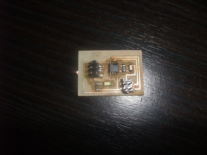
Wireless Bluetooth network.
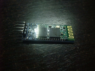
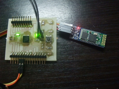
For wireless network, Again I am using the Atmega 328 with a HC-06 modue.
For wireless network, Again I am using the Atmega 328 with a HC-06 modue.
char blueToothVal; //value sent over via bluetooth
char lastValue; //stores last state of device (on/off)
void setup()
{
Serial.begin(9600);
pinMode(13,OUTPUT);
}
void loop()
{
if(Serial.available())
{//if there is data being recieved
blueToothVal=Serial.read(); //read it
}
if (blueToothVal=='n')
{//if value from bluetooth serial is n
digitalWrite(13,HIGH); //switch on LED
if (lastValue!='n')
Serial.println(F("LED is on")); //print LED is on
lastValue=blueToothVal;
}
else if (blueToothVal=='f')
{//if value from bluetooth serial is n
digitalWrite(13,LOW); //turn off LED
if (lastValue!='f')
Serial.println(F("LED is off")); //print LED is on
lastValue=blueToothVal;
}
delay(1000);
}
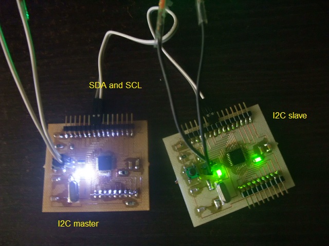
There are two firm wares, one for the master board and the other for the slave board. Here is how they works.
The master board will send a number from 0 to 5 in sequence at a 0.5 sec interval.
For the slave board, when it receives an integer 0 from the master, it will switch on the pin 13 LED for 200 ms. If the integer is 3. It will blink the LED 3 times at an interval of 400 ms.
Listed below is the I2C master code on the left and Slave on the right.
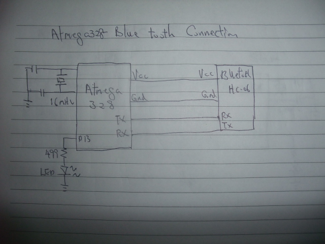
When the Bluetooth module is powered up, it is waiting to be pair. Go to setting section of a PC and look for available Bluetooth module to be pair. Look for HC-06. The paring password is “1234”.
Here is how the code works. After pairing. Open serial monitor and look for the Comm port for HC-06. If a character ‘n’ is sent and received by the Bluetooth-Atmega328, it will switch on the pin 13 LED and reply “LED is on”. On the other hand, sending a ‘f’ will switch of the LED and get a reply “LED is off””.
Here is how the code works. After pairing. Open serial monitor and look for the Comm port for HC-06. If a character ‘n’ is sent and received by the Bluetooth-Atmega328, it will switch on the pin 13 LED and reply “LED is on”. On the other hand, sending a ‘f’ will switch of the LED and get a reply “LED is off””.
Wired asynchronous network
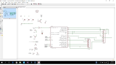
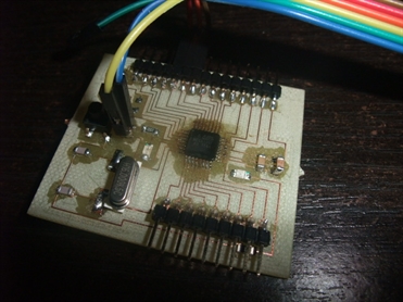
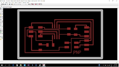
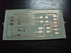
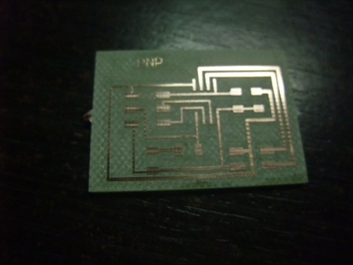
I use Neil’s hello.bus.45 design but modified it to use Attiny85, reason for using Attiny85 is I only have Attiny85 available. I first recreate the design using eagle files, mill the PCB and solder the components.
First we have the bridge.
I use Neil’s hello.bus.45 design but modified it to use Attiny85, reason for using Attiny85 is I only have Attiny85 available. I first recreate the design using eagle files, mill the PCB and solder the components.
First we have the bridge.
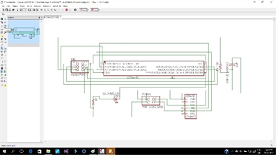
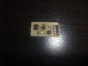
Then we have the node.
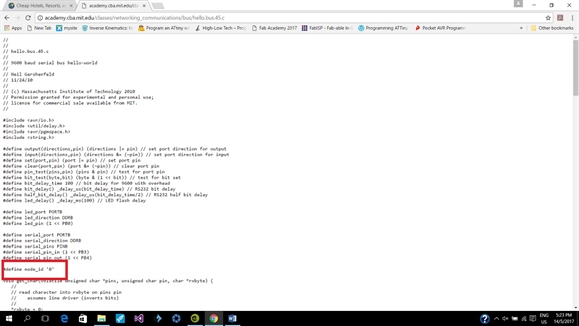
Firmware modification
Since I am using Attiny85, I went to the make file and change the MMCU to attiny85.
For the c.program.
for bridge use node_id ='0'
for node use node_id ='1'
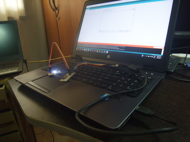
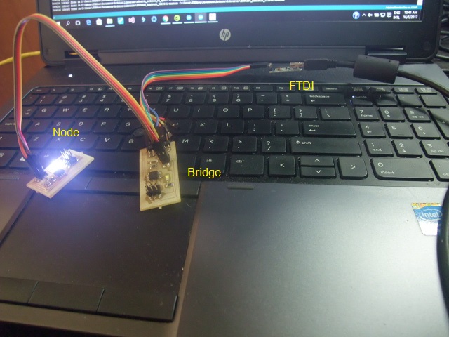
Connect the bridge board and
the node board with a 4 pin cable.
Connect the bridge to FTDI cable then to a USB port.
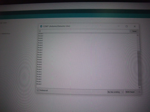
On the serial monitor, press 0 to light up LED on bridge and it will echo "node0" back to serial monitor.
Press 1 to lioght up LED on node and the node will echo "node1" back to serial monitor.
Since I am using Attiny85, I went to the make file and change the MMCU to attiny85.
For the c.program.
for bridge use node_id ='0'
for node use node_id ='1'
Connect the bridge board and
the node board with a 4 pin cable.
Connect the bridge to FTDI cable then to a USB port.
On the serial monitor, press 0 to light up LED on bridge and it will echo "node0" back to serial monitor.
Press 1 to lioght up LED on node and the node will echo "node1" back to serial monitor.
Reflection
I used Atmega 328 for the exercise because I am going to use them for final project as well.
I also discovered that doing a full rubout of PCB make soldering so much easier:), only thing is that it takes about 2 hours to mill a board with a 0.2mm bit :(
The I2C network has two 4.7K resistor pull up resistors for SCL and SDA lines respectively. However it can also work without them, but for reliability concern, I think I will just leave it there.
The serial network is only working at TTL level. The specification for RS232 is higher than 5V and requires a chip like Maxim Max232 to do level shifting.
I have a ESP8266 WIFI module at hand for WIFI or IOT project, but run out of time ( see below). Another time…:)