Output Device
Assignment
Add an output device to a microcontroller board you've designed and program it to do something
Add an output device to a microcontroller board you've designed and program it to do something
For this week assignment, I am starting to have this idea of using the weekly assignments to build up the final project, a robotic arm. For output device, I would like to have a LCD display and a stepper driver. And on input device, perhaps a keyboard or limit switch monitor board. Maybe it would be a good idea to links these devices with a RS485 or I2C during the network and communication assignment.
I will start with output device to make a microcontroller board based on Attiny 85, connect a graphic LCD to it as output device, program the microcontroller to display something. Next I will make a microcontroller based A4988 stepper driver board.
I will make the LCD display first to full fill the assignment requirement, the completion of the stepper driver is optional depends on how much time is left (Although I like to spend a lot of time doing this, but I still have a day job and need to keep the boss happy :])
As a habit, I always start my design on paper, make sure that there is enough though given to the design and it can be turned into a real working item. Like anybody, I would look around the internet to see if there is something closely resembled what I want to do that I can modify for my purpose.(Life is too short to reinvent the wheel everytimes : ). Then I will build a test piece using breadboard to make sure that all the hardware and software are working as planned before going to the CAD station to design the PCB. This way I know that if the final product is not working, it would just be the PCB assembly process.
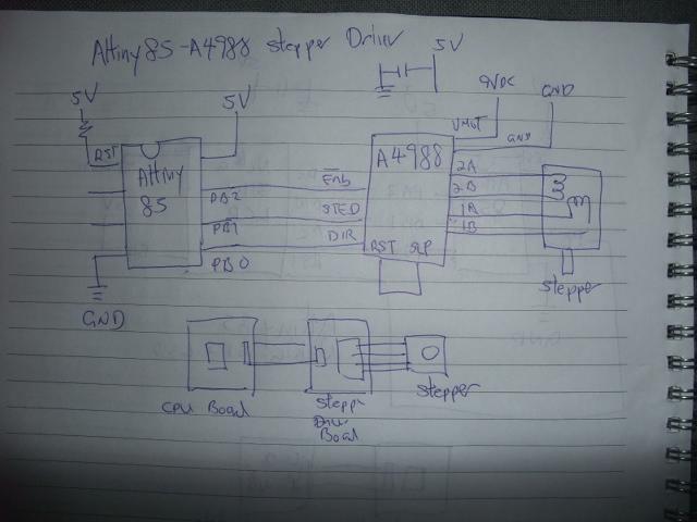
The conceptual design of the microcontroller LCD system is as shown below.
I will start with output device to make a microcontroller board based on Attiny 85, connect a graphic LCD to it as output device, program the microcontroller to display something. Next I will make a microcontroller based A4988 stepper driver board.
I will make the LCD display first to full fill the assignment requirement, the completion of the stepper driver is optional depends on how much time is left (Although I like to spend a lot of time doing this, but I still have a day job and need to keep the boss happy :])
As a habit, I always start my design on paper, make sure that there is enough though given to the design and it can be turned into a real working item. Like anybody, I would look around the internet to see if there is something closely resembled what I want to do that I can modify for my purpose.(Life is too short to reinvent the wheel everytimes : ). Then I will build a test piece using breadboard to make sure that all the hardware and software are working as planned before going to the CAD station to design the PCB. This way I know that if the final product is not working, it would just be the PCB assembly process.
The conceptual design of the microcontroller LCD system is as shown below.
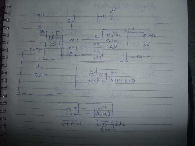
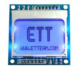
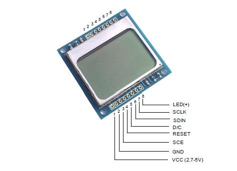
The graphic LCD is a 48 x 84 Dot LCD Display from Etteam.The datasheet can be downloaded from the link below:
http://skpang.co.uk/catalog/images/lcd/graphic/docs/User_Manual_ET_LCD5110.pdf
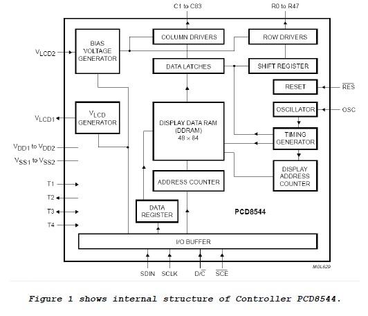
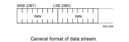
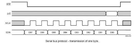
The format of command that is used to communicate with LCD is divided into 2 modes; Command Mode and Data Mode. In this case, it uses Pin D/C to divide and control signals; if D/C = 0, the data that is sent to LCD is Command (see more detailed information of commands in the Table 1); and if D/C = 1, the data that is sent to LCD wil1 be Data and it will placed in DDRAM Memory (Display Data RAM) to be displayed on LCD Display. After 1 byte data has already been written, 1 value of DDRAM address will be increased automatically. The format of data will be serial and it will send MSB (The Most Significant Bit) first. Generally, its structure is displayed as follows;
http://skpang.co.uk/catalog/images/lcd/graphic/docs/User_Manual_ET_LCD5110.pdf
The format of command that is used to communicate with LCD is divided into 2 modes; Command Mode and Data Mode. In this case, it uses Pin D/C to divide and control signals; if D/C = 0, the data that is sent to LCD is Command (see more detailed information of commands in the Table 1); and if D/C = 1, the data that is sent to LCD wil1 be Data and it will placed in DDRAM Memory (Display Data RAM) to be displayed on LCD Display. After 1 byte data has already been written, 1 value of DDRAM address will be increased automatically. The format of data will be serial and it will send MSB (The Most Significant Bit) first. Generally, its structure is displayed as follows;
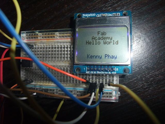
I have a DIP packaged Attiny85 so I can test the circuit before committing it to Eagle Cad and PCB fabrication,
The breadboard test set up and the Arduino sketch are shown below. The Library driving the LCD is from basic library LCD5110_Basic of henningkarlsen.com, link is below:
http://www.rinkydinkelectronics.com/library.php?id=44
The breadboard test set up and the Arduino sketch are shown below. The Library driving the LCD is from basic library LCD5110_Basic of henningkarlsen.com, link is below:
http://www.rinkydinkelectronics.com/library.php?id=44
// SCK (CLK) ------- Attiny85 pin 5
// MOSI (DIN)------- Attiny85 pin 6
// DC (register select) ------- Attiny85 pin 7
// RST ------- Attiny85 pin 2
// CS (CE) ------- to GND
//LCD5110 myGLCD(0, 1, 2, 3, 6); //D6 don't exist - conect CS to GND
extern uint8_t BigNumbers[];
void setup(void) {
myGLCD.InitLCD();
myGLCD.clrScr();
}
void loop(void) {
myGLCD.setFont(SmallNumbers);
myGLCD.clrScr();
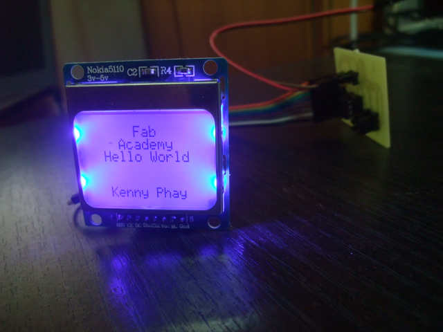
myGLCD.printNumF("Fab", 1, CENTER, 14);
myGLCD.printNumF("Academy", 1, CENTER, 14);
myGLCD.printNumF("Hello World", 1, CENTER, 14);
myGLCD.printNumF("Kenny Phay", 1, CENTER, 14);
}
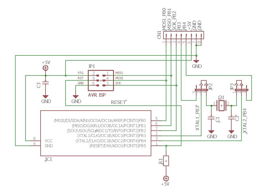
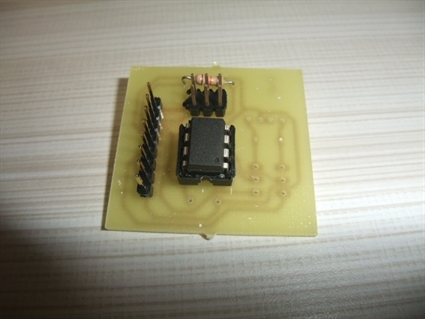
Atting 45/85PCB design, fabrication and assembly
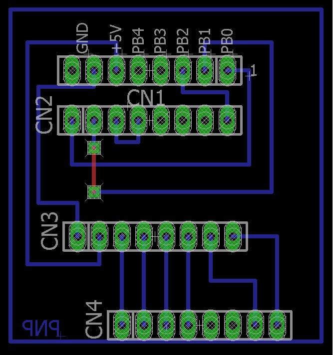
I have been using all SMD assembly for the past assignment. I have some experiences that the SMD connector came off after prolong use. As I am going to use the assignment’s output devices for my final project. I decided to try out PTH components especially for the connector for better durability and reliability. There is additional process of drilling holes for component mounting but I think it is worth the time
I have been using all SMD assembly for the past assignment. I have some experiences that the SMD connector came off after prolong use. As I am going to use the assignment’s output devices for my final project. I decided to try out PTH components especially for the connector for better durability and reliability. There is additional process of drilling holes for component mounting but I think it is worth the time
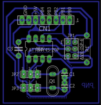
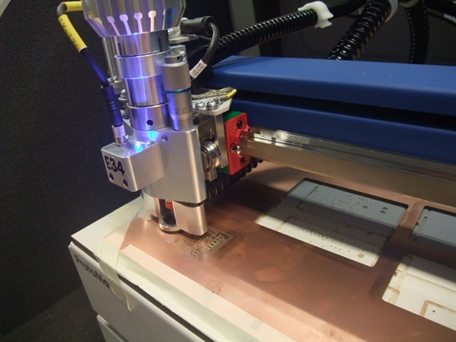
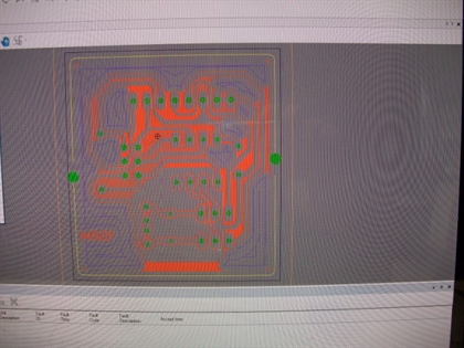
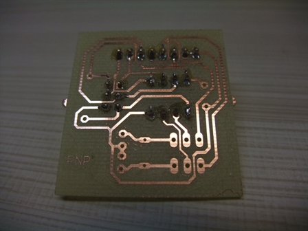
Nokia5110 LCD PCB design, fabrication and assembly
A4988 stepper driver board
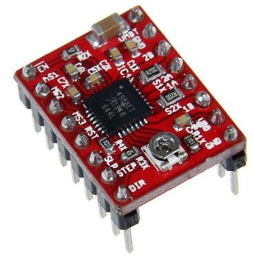
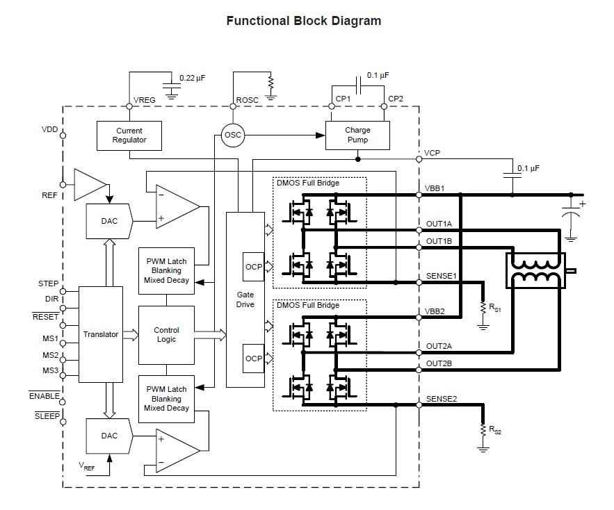
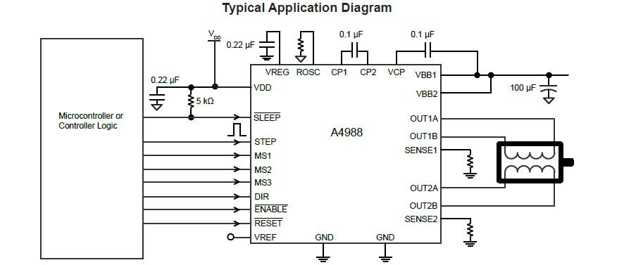
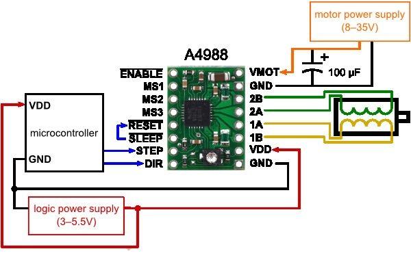
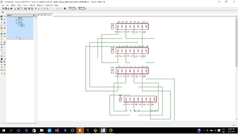
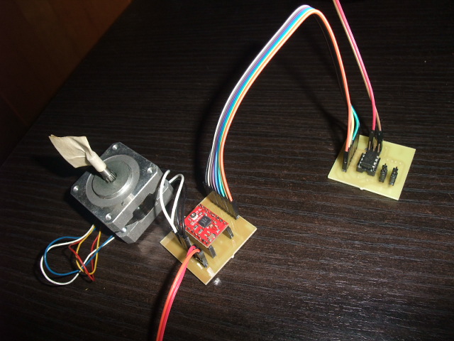
The next output device I will be making is a Attiny85 based stepper driver board based on A4988 driver module.
The next output device I will be making is a Attiny85 based stepper driver board based on A4988 driver module.
The A4988 is a complete microstepping motor driver with built-in translator for easy operation. It is designed to operate bipolar stepper motors in full-, half-, quarter-, eighth-, and sixteenth-step modes, with an output drive capacity of up to 35 V and ±2 A. The A4988 includes a fixed off-time current regulator which has the ability to operate in Slow or Mixed decay modes.
The datasheet of A4988 can be downloaded from the link below:
https://www.pololu.com/file/download/a4988_DMOS_microstepping_driver_with_translator.pdf?file_id=0J450
The datasheet of A4988 can be downloaded from the link below:
https://www.pololu.com/file/download/a4988_DMOS_microstepping_driver_with_translator.pdf?file_id=0J450
// Run a A4998 Stepstick from an Attiny85
// Kenny Phay Apr 2017
int x;
void setup()
{
pinMode(2,OUTPUT); // Enable
pinMode(1,OUTPUT); // Step
pinMode(0,OUTPUT); // Dir
digitalWrite(2,LOW); // Set Enable low
}
void loop()
{
digitalWrite(2,LOW); // Set Enable low
digitalWrite(0,HIGH); // Set Dir high
for(x = 0; x < 200; x++) // Loop 200 times
{
digitalWrite(1,HIGH); // Output high
delay(100); // Wait
digitalWrite(1,LOW); // Output low
delay(100); // Wait
}
delay(1000); // pause one second
}
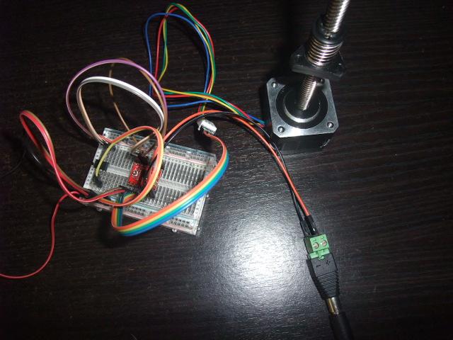
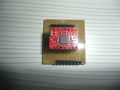
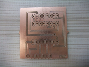
After testing the circuit on a breadboard. Here are the A4988 Stepper driver board PCB design, fabrication and assembly
Reflection
It would be easier to just follow the designs provided by Neil. But it is more fun to define what I want and make it works.
It would be easier to just follow the designs provided by Neil. But it is more fun to define what I want and make it works.