Exercise 15 - Networking and Communications
Assignment for this week
I2C Communication
For this week assignment, I would like to explore I2C Communication. The Inter-integrated Circuit (I2C) Protocol is a protocol intended to allow multiple “slave” digital integrated circuits (“chips”) to communicate with one or more “master” chips. Like the Serial Peripheral Interface (SPI), it is only intended for short distance communications within a single device. Like Asynchronous Serial Interfaces (such as RS-232 or UARTs), it only requires two signal wires to exchange information.

The I2C bus uses two wires: serial data (SDA) and serial clock (SCL). The I2C master and slave devices are connected with only those two wires. The master generate bus clock and initiate communication on the bus, slaves devices then respond to the commands on the bus. In order to communicate with specific device, each slave device must have an address which is unique on the bus. I2C master devices (usually microcontrollers) don't need an address since no other (slave) device sends commands to the master.
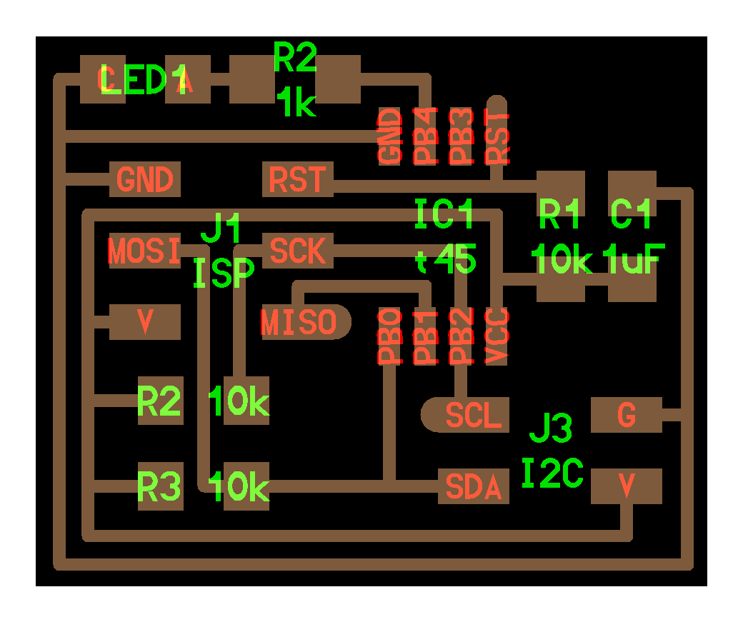
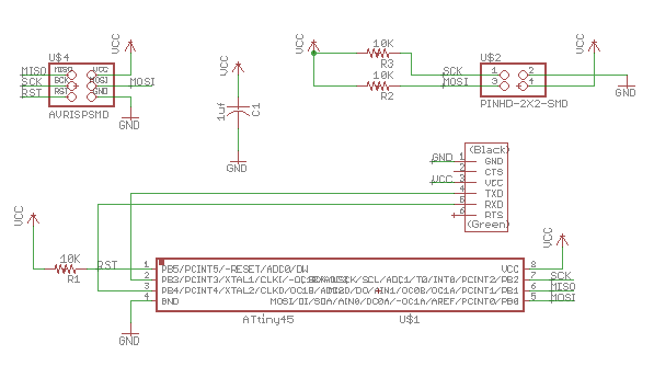
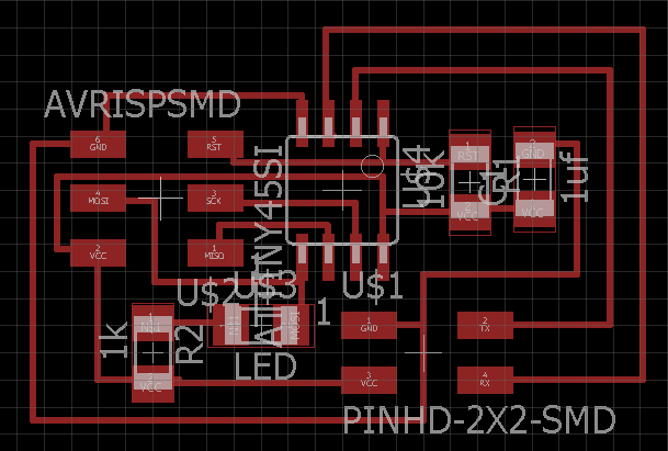
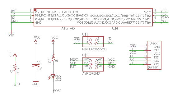
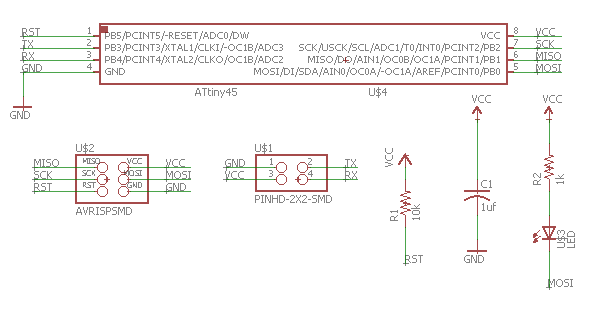
With reference to Arduino playground and The Wandering Engineer, I would like to try out using Arduino Uno as the master and the Hello Board I created in Exercise 6 as the slave.
Pin Connection
| ATtiny85 | Pin 5 | Pin 7 |
| Arduino UNO | A4 | A5 |
The connection for the Master and Slave will be simliar to that of the I2C diagram above except there is only one master and a Slave. 2 resistors of value 4.7K is used.
Before I proceed to test the code, I need to download ATtiny 85 i2c slave library. Next I will have to program the Hello board as the slave using the FabISP and then later uses the "SCK" pin and "MOSI" pin at the ISP Pin header as the "SDA" and "SCL" respectively.
The following is the code used
Master - Arduino Uno
#include (Wire.h)

void setup()
{
Serial.begin(9600);
Wire.begin();
Serial.println("'a' - Enter Character a to turn on Slave 1 LED");
Serial.println("'b' - Enter Character b to turn off Slave 1 LED");

}

void loop()
{

while(Serial.available())
{
char c = Serial.read();
if (c == 'a')
{
Wire.beginTransmission(1);
Wire.write('a');
Wire.requestFrom(1, 1);// request from slave device #1
while (Wire.available()) { // slave may send less than requested
Serial.println("LED is on from Slave");
int x =Wire.read();
Serial.println(x);// print the character
}
Wire.endTransmission();
delay(1000);

}
else if (c == 'b')
{
Wire.beginTransmission(1);
Wire.write('b');
Wire.requestFrom(1, 1);// request from slave device #1
while (Wire.available()) { // slave may send less than requested
Serial.println("LED is off from Slave");
int x =Wire.read();
Serial.println(x);// print the character
}
Wire.endTransmission();
delay(1000);
}
}
}
Slave - Hello Board
#include (TinyWireS.h)

// Code for the ATtiny85

#define I2C_SLAVE_ADDRESS 0x1 // Address of the slave

int i=1;
void setup()
{
TinyWireS.begin(I2C_SLAVE_ADDRESS); // join i2c network
TinyWireS.onReceive(receiveEvent);

// Turn on LED when program starts
pinMode(PB1, OUTPUT);
}

void loop()
{
// This needs to be here
TinyWireS_stop_check();
}

void receiveEvent()
{

while(TinyWireS.available())
{
char c = TinyWireS.receive();

if(c == 'a')
{
digitalWrite(PB1,HIGH);
TinyWireS.send(i);
}
else if(c == 'b')
{
digitalWrite(PB1,LOW);
TinyWireS.send(i);
}
}
}
Understanding the program
When character a is enter in serial monitor, the slave turn on the LED and response with integer 1. When character b is enter in serial monitor, the slave turn off the LED and response with integer 1. Integer 1 is to indicate it is slave number 1.
I2C Bridge and Node
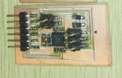
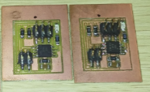
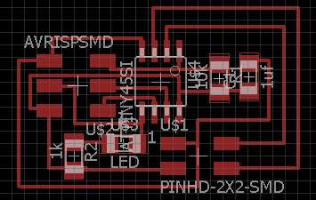
Next attempt is to make 3 boards (one bridge and 2 nodes) to communicate with one another. With reference to the class site, I would be referring to Neil's boards in my design, a hello.I2C.45.bridge and hello.I2C.45.node will be created in Eagle.
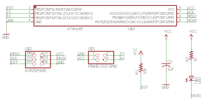
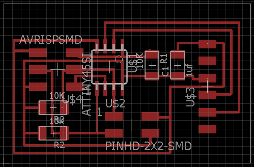
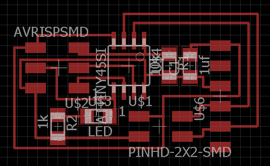
Once is ready, prepare to mill the board using PCB2020B. Details of the milling process has been documented in those week which involved Electronic Production so will not be repeated.
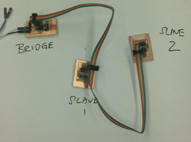
Testing the I2C Bridge and Node
Before we proceed to test the I2C bridge and nodes, two important library to be downloaded when using Arudino IDE - TinyWireM and TinyWireS. The following simple code has been used for the communication for the bridge and the two nodes.
I2C Bridge
#include (TinyWireM.h)
#define device (1)
#define slave (2)
void setup() {
TinyWireM.begin();
}
void loop() {
TinyWireM.beginTransmission(device);
TinyWireM.send(1);
TinyWireM.endTransmission();
delay(2000);
TinyWireM.beginTransmission(device);
TinyWireM.send(0);
TinyWireM.endTransmission();
delay(2000);
TinyWireM.beginTransmission(slave);
TinyWireM.send(1);
TinyWireM.endTransmission();
delay(2000);
TinyWireM.beginTransmission(slave);
TinyWireM.send(0);
TinyWireM.endTransmission();
delay(2000);

}
I2C Node
#include (TinyWireS.h)
int output=PB4;
#define I2C_SLAVE_ADDR (1)
void setup() {
// put your setup code here, to run once:
TinyWireS.begin(I2C_SLAVE_ADDR);
pinMode(output, OUTPUT);
}
volatile byte msg = 0;
void loop() {
if (TinyWireS.available())
msg = TinyWireS.receive();
if (msg == 1)
digitalWrite(output, HIGH);
else if (msg == 0)
digitalWrite(output, LOW);
else
msg = 0;
}
Understand the program code
For the other node, change the above code #define I2C_SLAVE_ADDR (1) > #define I2C_SLAVE_ADDR (2). The program is written is such that the master is communicating with the node which has adddress 1, and then send a 1 and 0 to the node. The node with addrees 1 will then respond by turning ON and OFF the LED which correspond with the condition set with the message receive. Next, the master then communicate with address 2 and then the process is repeated.
Asynchronous Serial Communication boards
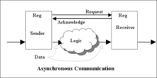
Decided to try and build an asynchronous serial communication network. According to Wikipedia - on Asynchronous Communication, it is the transmission of data without the use of an external clock signal, where data can be transmitted intermittently rather than in a steady stream. In asynchronous transmission, data is sent one byte at a time and each byte is preceded by start bit and stop bit. This site gives a comparison between synchronous and asynchronous transmission.
Asynchronous Bridge and Node
Like I2C, it will have one bridge and 2 nodes to communicate with the computer via a FTDI interface. With reference to the class site, I would be referring to Neil's boards design, a hello.bus.45.bridge and hello.bus.45.node will be created in Eagle.
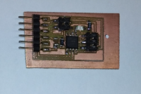
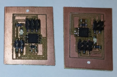
Once is mill using PCB2020B, next is to stuff the board with the necessary components and then get ready to test the program code.
Testing the asynchronous Bridge and Node
Using Neil code from the class site. After successfully loaded using Atmel Studio, realise that when a "0" is enter in terminal, all LEDs from the bridge and nodes blink together. Then enter a "1" produce the same result. Later when enter any other keys, the same result return. Spent quite sometime to troubleshoot and understand the C code but it doesn't quite seem to work. Next decided to try the simple blinking program on the 3 boards in Arduino. All the 3 boards are able to response and working well.
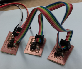
Gather my classmates for discussion and decided to write code in Arduino to try out the asynchronous bridge and node. After which, each board is being tested on its Transmit and Receive, the response to character enter in serial monitor. As the node does not have the FTDI pin header so it is connecting through the 4 pin header. Upon confirming that the 3 boards work individually, proceed to connect all 3 boards and run the code using Arduino IDE.
Asynchronous Bridge and Node
#include "SoftwareSerial.h"

const int rx=PB3;
const int tx=PB4;
int node=48;    // Change accordingly - Number 48 as node 0, 49 as node 1, 50 as node 2
int x=0;

// the setup function runs once when you press reset or power the board
SoftwareSerial mySerial(rx, tx);

void setup() {
  // initialize PB0 as an output.
    mySerial.begin(9600);
  pinMode(PB0, OUTPUT);
  digitalWrite(PB0, HIGH);
}

// the loop function runs over and over again forever
void loop()
{
  if(mySerial.available() > 0)
  {
    x=mySerial.read();

  if (x==node)
    {
    digitalWrite(PB0, LOW);   // turn the LED on (HIGH is the voltage level)
    delay(500);
    digitalWrite(PB0, HIGH);
    delay(500);
    mySerial.print("Responding from node: ");
    mySerial.print(x);
        }
  }
}
The result is not what I expected. Although the LEDs for each board do blink and response to the input enter in serial monitor, but the serial print in the condition loop did not show up even though the number enter correspond to what stated in the condition. Did not proceed to test out further instead one of my course mates suggested to reload the Neil's code.
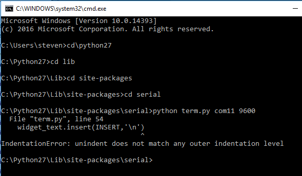
After reload Neil's code, when run the term.py there is an error message on IndentationError. The same file runs on my course mates laptop. So decided to give a last try on my laptop using the Serial Monitor from Arduino. The result seem to be better as both node 0 and node 1 both blink and responded in serial monitor. For node 2, it is unstable and returning garbages.
My Thought
Whenever it comes to Electronics, is always frustrating when the circuit didnt work after the components stuffing. Soldering on SMD components requires patience and concentration. For someone who are already struggling to read small letters on newspaper and magazine is even worse. The pressure on doing it right and getting it work is so stressful. Not forgetting that schematic creation, routing and milling the circuits already took some time. Then come the testing and programming of the circuit, trying to understand the C code is not an overnight event. Fallling back using Arduino IDE was the option that I took. But neither option is a good option for me as I am not familiar with programming but still have to give it a try. Nevertheless when you see the board you have mill, components you have spent time stuffing and then the program written works, it is such a great relief. Like what I have said before - Programming is an art if one really understand and know how to use it. Because you creates something out of nothing. Is this the last Electronics board that I going to make guess I still have my final project to worry :).