Exercise 15 - Embedded Networking and Communications
Requirement
- Design and build a wired and/or wireless network connecting at least two processors .
I²C (Inter-Integrated Circuit)
I-squared-C, is a multi-master, multi-slave, packet switched, single-ended, serial computer bus invented by Philips Semiconductor (now NXP Semiconductors). It is typically used for attaching lower-speed peripheral ICs to processors and micro-controllers in short-distance, intra-board communication. Alternatively I²C is spelled I2C (pronounced I-two-C) or IIC (pronounced I-I-C)
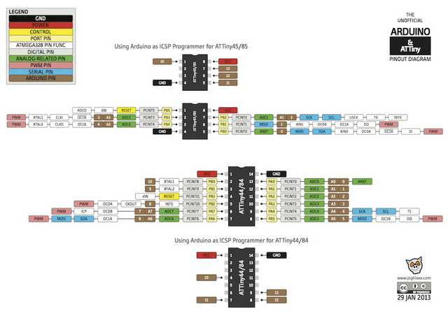
For this week assignment, I started with Arduino Uno (Atmega 328p) to communicate with another MCU (ATtiny45). Using Atmega 328p as a Master and the ATtiny as a Slave receiving signal/ commands to "ON" and "OFF" the LED.
Each I²C bus consists of two signals: SCL and SDA. SCL is the clock signal, and SDA is the data signal. The clock signal is always generated by the current bus master
Arduino Uno (Atmega 328p) and ATtiny45
With reference to the data sheet, Pin 27 (PC4) and Pin 28 (PC5) on the Atmega 328p is the dedicated pin for SDA and SCL.
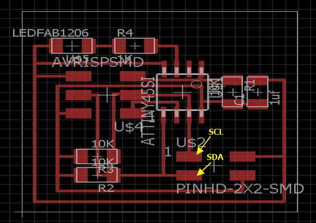
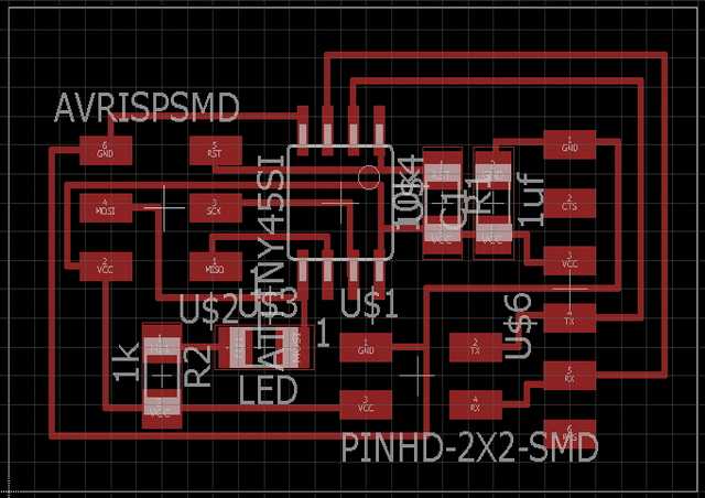
Instead of using Arduino Uno, I mill out a FABkit v4 and a communication board using ATtiny 45 with both SCL and SDA pin connected to pin header. Milling of board is explained in week 4 so will not further explain on this.
In order for ATtiny MCU to communicate using I²C, new libraries need to be install into Arduino IDE. As a Master ->TinyWireM, as a Slave ->TinyWireS.
To include library in Arduino IDE. TinyWireM.h as master and TinyWireS.h as slave
    #include "TinyWireM.h"
    #include "TinyWireS.h"
In I2C, setup initialization uses the command "begin". As a Master in I2C, address is not require.
    void setup()
    {
      TinyWireM.begin();
    }
But as a Slave in I2C, user need to predefine an address for the MCU
    #define I2C_SLAVE_ADDRESS 0x6

    void setup()
    {
      TinyWireS.begin(I2C_SLAVE_ADDRESS); // join i2c network as slave
    }
Examples are included when both the library are install, or more example can be found on the web site (TinyWireM, TinyWireS).
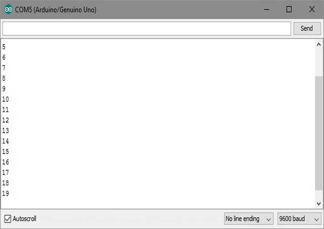
Using IDE to program the slave to "ON" the LED when program start and then send an incremental single byte to master. Master will display the increasing number in serial monitor.
I²C between 2 slaves and 1 Master
With the basic testing done, moving forward will trying to connect 3 MCUs together. Communication between a master and 2 slaves.
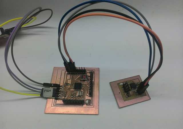
Connnection using SDA, SCL pins (PB0 and PB2) and a common Vcc and Gnd. Milling of board is explained in week 4 so will not further explain on this.
The program: Master MCU will communicate to the slave/s MCU/s which join the network by sending "1" and "0" to "ON" and "OFF" the on board LED, at the sametime slave/s will send a feedback to master that the LED is either "ON" or "OFF" through FTDI and display on the serial monitor.
    void loop()
    {
    TinyWireM.beginTransmission(device);
    TinyWireM.send(1);
    TinyWireM.endTransmission();
    inputmsg1();

    TinyWireM.beginTransmission(device);
    TinyWireM.send(0);
    TinyWireM.endTransmission();
    inputmsg1();

    TinyWireM.beginTransmission(slave);
    TinyWireM.send(1);
    TinyWireM.endTransmission();
    inputmsg2();

    TinyWireM.beginTransmission(slave);
    TinyWireM.send(0);
    TinyWireM.endTransmission();
    inputmsg2();
    }

    void inputmsg1()
    {
      volatile byte msg =0;
      TinyWireM.requestFrom(device,1);

      if (TinyWireM.available()){
        msg = TinyWireM.receive();}
      if (msg ==2){
        mySerial.println("Slave 1 LED On");}
      else if (msg ==3){
        mySerial.println("Slave 1 LED Off");}
      else
        {}
    }

    void inputmsg2()
    {
      volatile byte msg =0;
      TinyWireM.requestFrom(slave,1);

       if (TinyWireM.available()){
        msg = TinyWireM.receive();}
       if (msg ==4){
        mySerial.println("Slave 2 LED On");}
       else if (msg ==5){
        mySerial.println("Slave 2 LED Off");}
       else
        {}
    }
Asynchronous Communication
With some time left, I decide to try out asynchronous serial communication.
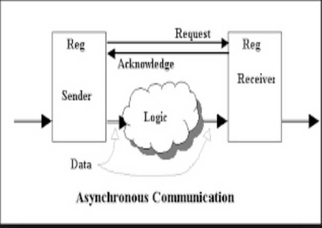
Asynchronous communication is transmission of data, generally without the use of an external clock signal, where data can be transmitted intermittently rather than in a steady stream. The most significant aspect of asynchronous communications is that data is not transmitted at regular intervals, thus making possible variable bit rate, and that the transmitter and receiver clock generators do not have to be exactly synchronized all the time. In asynchronous transmission data is sent one byte at a time and each byte is preceded by start bit and stop bit.
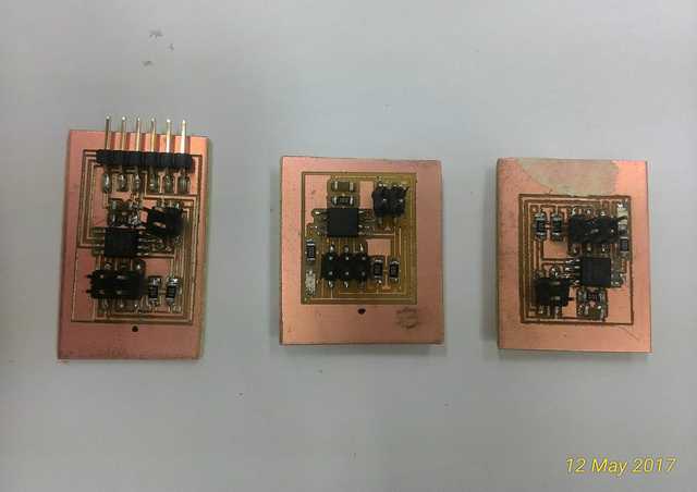
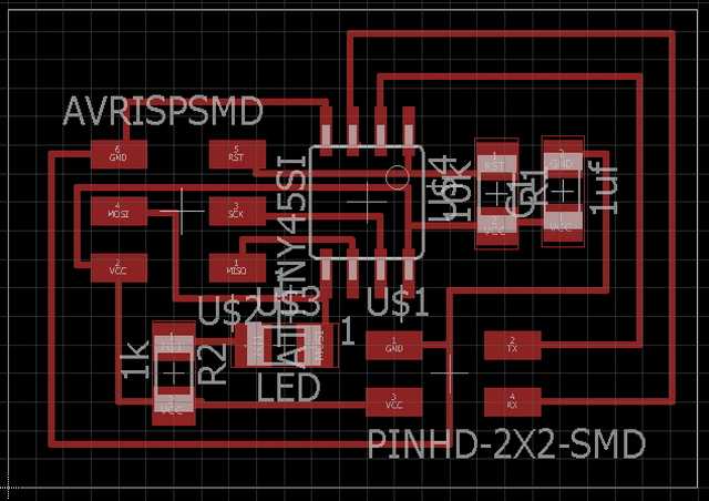
With reference to Neil's design, we milled out 1 bridge and 2 nodes for asynchronous serial communication testing. Milling of board is explained in week 4 so will not further explain on this.
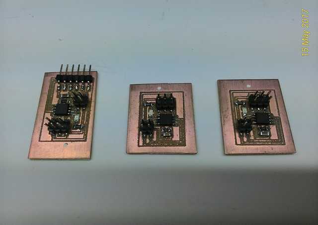
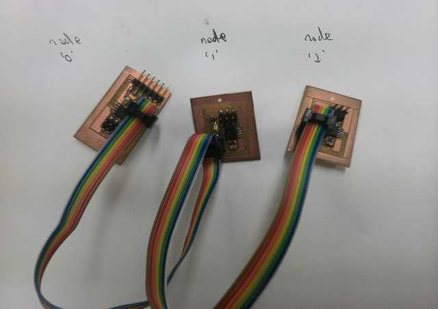
After stuffing all the boards, and using Neil's C code to program all the boards. The only different and only changes to make in coding is the individual node ID. Neil's C code can be found here under serial bus communication.
    #define node_id '0'   for ID Node 0
    #define node_id '1'   for ID Node 1
    #define node_id '2'   for ID Node 2
When user press "0" all the boards will blink once, only the board with ID 0 (bridge)will blink twice. The result is the same for both "1" and "2" (Node1 and Node2)
Problem encounter: Using the same coding for Node 0 and Node 1. Node 2 for unknown reason, feedback acknowledgment return rubbish but LED is responding well. Need further troubleshoot when time permits.
And I also write something similar and simple in IDE sketch to test the serial communication. I was able to get the right nodes and bridge to light up on the assigned keys (ID 0 to 2) but was unable to get the return message from either boards. Still work in progress, will be back if times allows
My thoughts
Network communication is a very big topic which consist of many method and different devices, but getting the I2C to work is really some accomplishment done.
Download
My I2C Master - Fabkit v4
My I2C Slave - ATtiny45 (Arduino IDE)
My I2C - ATtiny45 (Board)
My I2C - ATtiny45 (Schematic)
My I2C Master - ATtiny45 (Arduino IDE)
My Slave 1 - ATtiny45 (Arduino IDE)
My Slave 2 - ATtiny45 (Arduino IDE)
My Serial - bridge using ATtiny45 (Board)
My Serial - bridge using ATtiny45 (Schematic)
My Serial - Node using ATtiny45 (Board)
My Serial - Node using ATtiny45 (Schematic)
My Serial - communication (Arduino IDE)
References
Wikipedia - I²C
Atmega 382p - Data sheet
Wikipedia - Asynchronous communication
Return to top