Exercise 3 - Computer-controlled cutting
Requirement
- Design, make, and document a parametric press-fit construction kit.
- Cut something on the vinyl cutter.
What is parametric in design?
Parametric originates from mathematics (parametric equation) and refers to the use of certain parameters or variables that can be edited to manipulate or alter the end result. In our case, alter the design dimension base on changes.
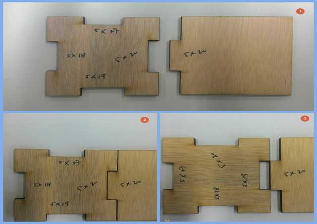
Understanding Kerf.
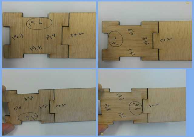
Before going into the laser machine to cut out the press-fit kit, we need to find out about Kerf. Kerf in short is how much material the laser cutter burns away when cutting specific materials. For better understanding of Kerf, can visit Ponoko for a much detail write-up.
Fablab@SP is equipped with a few different laser cutters. So this week, I decided to experiment with Universal laser (VLS 660): to find out the Kerf with preset setting. VLS 660 is a 60w laser cutter with a cutting table of est 800mm x 450mm.
The Preset setting contain information on how much "Power": strength of laser, "Speed": how fast the laser head move, "PPI" refer to pulses per inch and "Z-axis": for material thickness.
Setting for laser machine is like using a pen-knife, strength = how hard to press the knife, speed = how fast to move the knife and setting will varies from different materials and different thickness. With the above concept, after some trial and error with the setting on different materials, we came up with those few predefine setting.

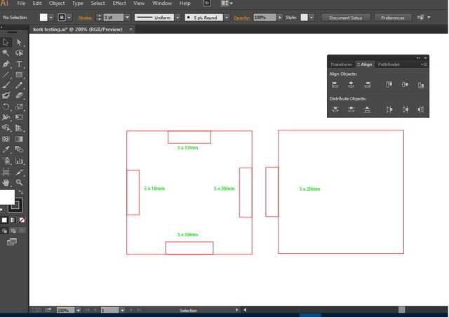
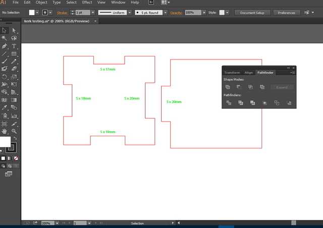
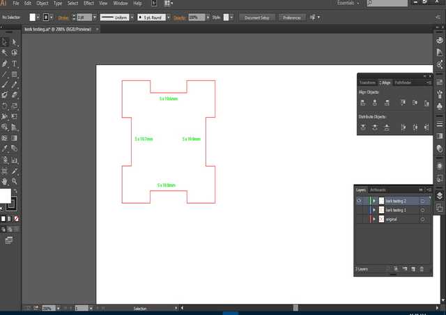
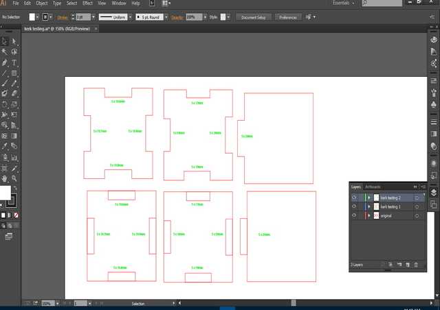
Adobe Illustrator (AI), AutoCad and CorelDraw are some of the software use to communicate between the laser cutter and user design. As I am more familiar AI, I come up with a simple finger joint to test out Kerk of this laser cutter.
Using the Laser cutter for press-fit construction kit.
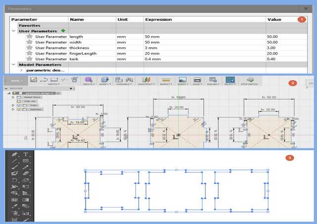
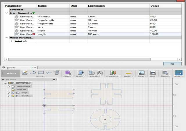
After I found out the Kerf for the laser cutter. I design a press-fit box using Fusion 360 which equipped with parametric design: where user can define and make change to thickness, length, width, Kerf and finger length as and when needed.
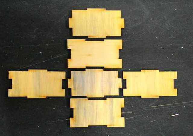
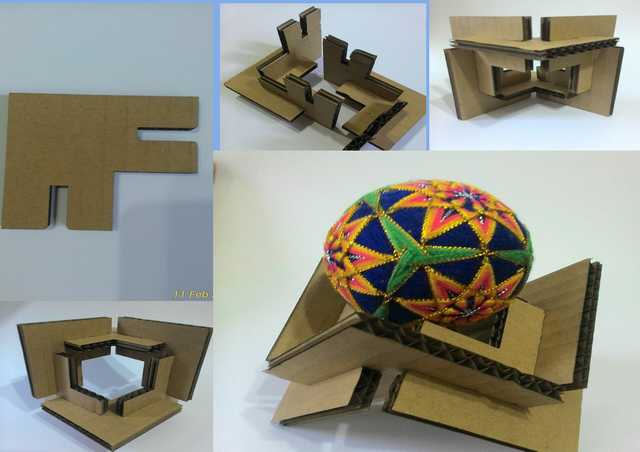
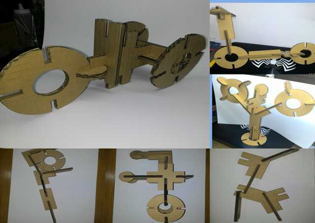
Press-Fit construction kit
Instead of just making a box or dice, I wanted something fun and interesting. So after surfing the web for some ideas, I come with the following press-fit kit.
I am using Fusion 360 to design the kit, with the help of parametric function I am able to adjust the size as and when there are change.
Laser cut process
The laser machine (Universal laser system) is configure to work with Adobe Illustrator (AI), so user only need to make their design in AI and print (ctrl + p) to the laser machine. We have also predefine some setting for some common material, user will then load using the predefine setting for different material before cutting
- Make design in AI
- Print design over to laser machine (ctrl + p)
- Load predefine setting according to material or set your on setting in laser control panel
- Place and align material into machine
- Start laser cutting, remove all material from cutting table after done
Points to take note:
- Laser cutter like a color printer operate on consumables (toner) in this case Carbon Dioxide (CO2) tube. So Setting might varies over time depending on usage.
- Different materials require different setting.
- Materials must be laid flat, for best result.
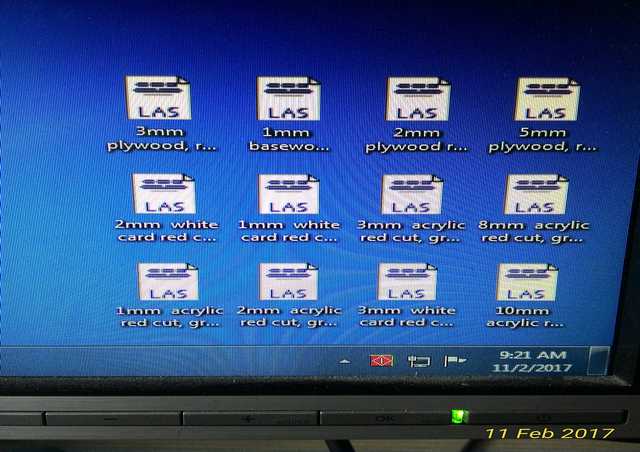
Links for the above file.
- Kerf Design in AI.
- Test fit box in AI.
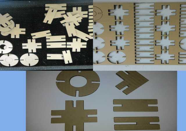
- Corrugated cardboard shape in AI.
- Test fit box in Fusion 360.
- Corrugated cardboard shape in Fusion 360.
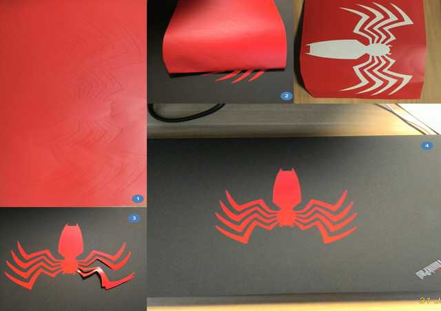
Vinyl cutting
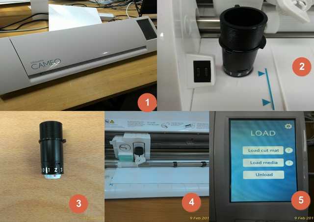
In our FabLab and MakerSpace (located in the library), they are equipped with Silhouette Cameo- a digital cutter which is able to do vinyl cutting.
Silhouette Cameo also comes with a free software - Silhouette Studio® which is able to work in both windows and Mac, and now there is even a mobile version for IOS, Android, Windows and Kindle.
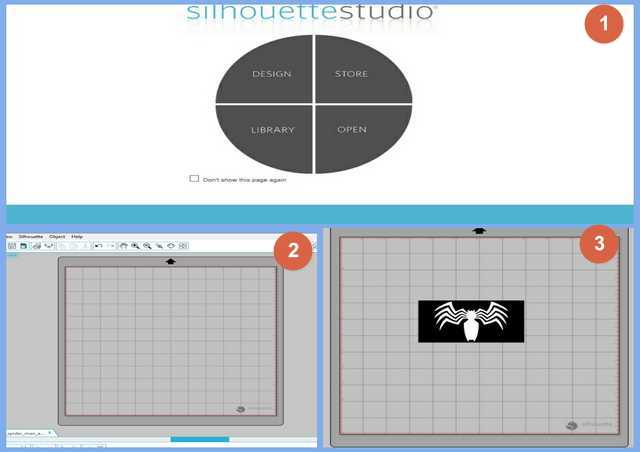
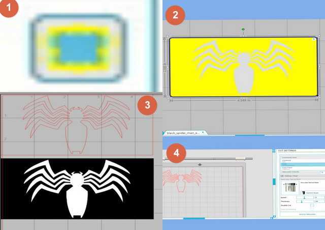
Silhouette Studio is an easy and user friendly software where it provide shapes, lines, text where user can work on it, or user can import images (jpg), trace it then send for cutting.
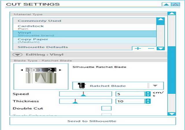
![]()
Points to take note:
- Cutting is easy. But if your design is complicated, pasting it will be a challenge, unless you have transfer tape.
- Cut setting will varies, depending on usage due to wear and tear.
Links for the above file.
My thoughts
With the help of technology, machine like Laser cutter and vinyl cutter can replace lots of manual cutting using pen knife, but one still need to master the software first else the machine useless.References:
Return to top