~ Computer controlled machining.
~ post date: 2017.3.15, recent update: 2017.6.24
Computer Numerical Control (CNC) is a method of directing machines via a computer programmed sequence of commands. Without requiring human involvement in intricate machine movement, a significantly higher design fidelity and accuracy is possible. Further, translating computer produced designs into machine made things can be a more faithful procedure and highly replicable. Not all machines can do all things, however, and unique material qualities influence variable machine outcomes. Until machines are able to recognize their own shortcomings and adjust accordingly, we need to be machine literate.
In this post, I will be exploring the possibilities of a CNC three-axis mill cutting plywood strictly two-dimensionally. I plan to create a kit of parts that when combined make a big three-dimensional thing. The process will be quickly creating an initial generative design influenced heavily by precedent, testing machine and material constraints based on the hopes of the design, tuning the design and finally producing a first prototype.
Update : The CNC mill we have access to from Fablab O is owned and placed in the Tongji University workshop. As Fab Academy students, we have extremely limited access to the machine both in time (a four hour window in the evenings shared with all the students from the university) and in software and hardware, both of which need to be channelled through the hands of a student lab assistant (with limited language overlap). We are not permitted to touch the machine or generate our own machine code for cutting. This arrangement is extraordinarily difficult to overcome and has made doing experimentation and testing on the mill infeasible. Therefore, I will not be able to cut my "Testing Constraint" design. Instead, I am attempting to cooperate with the workshop to cut a frame for my final work.
Project files
Unravel : Mysteries, preparing a design.
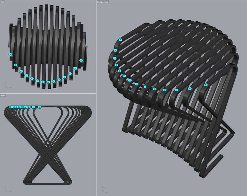
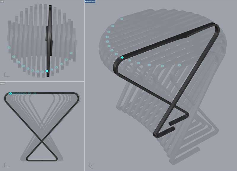
I wanted to make a work that appeared to be a single surface looped around and around like a coil or a spring. I like to make things that use machines natural ease in replication as a starting point and then find ways to create variation or intrigue. It could be imagined that this one thing can be unwound into a long straight line or that this coiled state is the natural tendancy of the material.
One important note: in this first prototype I plan to use machine kerf to make the plywood flexible in specific zones. In future iterations of this project or similar designs, I would like to explore bending, for instance with steam, and/ or finishing to conceal the intentional kerf.

I started using a combination of Maya, Rhinoceros and Grasshopper. I hope to have time after my first built prototype to convert the entire model into a grasshopper definition for versioning. For me, it is yet difficult to start a design in grasshopper. I like to design more like sculpting: adding material, tearing material away, fast, intuitive and sloppy, which is easy in Maya and once I have a clearer version of the design, I can begin translating the variables into Grasshopper and create a generative model. Nonetheless, Maya does propogate several changes throughout its history. As I starting point, I intend to use 10mm thick plywood and the overall dimensions fit within a 600mm x 600mm x 600mm virtual box. That may change with material testing. The ribbon is typically 20mm wide.
The bending areas will be living hinges from tool kerf. I need to test what the best pattern for this will be and optimize the radii. I think I prefer just a simple straight line cut through the top few layers of plywood which research suggests work in both directions. That is good, because the bends are reversed from top to bottom. Thr project will look cleaner with the cuts facing inward which could be achieved by flipping the material between cuts. Flipping the material is a complication I will reserve for a later version. Otheriwse, the kerf will need to cut through the thickness of the material and the bands at 20mm may be too thin.
Fourteen bands are broken out of the one continuous band in the digital model. Material constraints primarily dictate this decision. I could reduce the number of bands if the joints were not aligned which may be interesting if not for the structural challenges of putting joints anywhere but the bottom where there is the least amount of vertical momentum. I think for the first version, there are enough challenges withstanding. Thus, the joints will be in the center of the base.
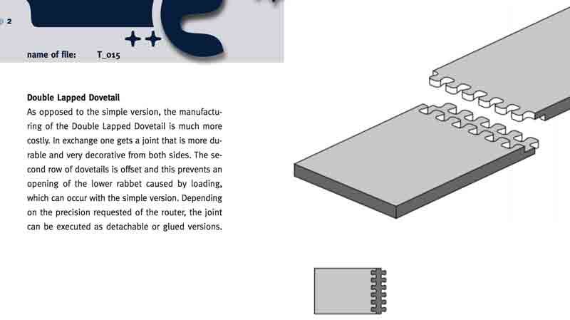
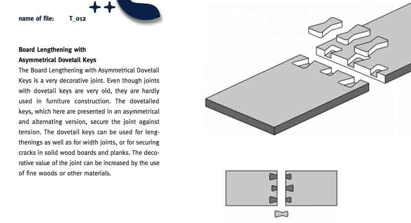
A benefit to flipping the material between cuts is the possibility of making a lapped dovetail joint which I think would be stronger. As I am not flipping the material between cuts, I will do a start with a variation of dovetail cut through.
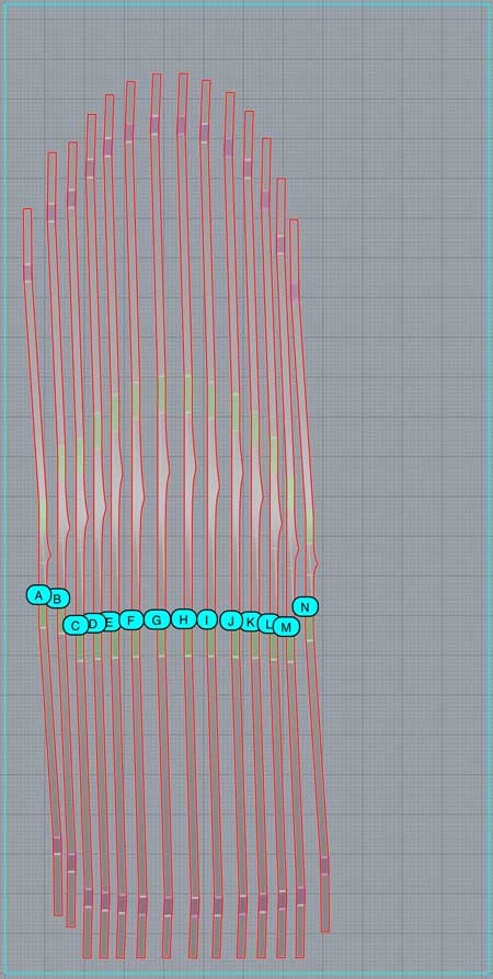
This drawing is for reference. It shows the current size of the cuts relative to the stock. The kerf patterns need to be optimized in testing and then I will likely extend the cuts beyond the red lines (full cuts). Plus, the joint needs to be added to the ends after testing. Then I can optimize the positioning to save material. No reason to do that effort before finalizing the cut shapes. The purple zones are 20mm radius bends and the green 40mm. The darkest lines of the grid are spaced 100mm.
I will post links to resources I have found helpful here.
Testing constraint : machining materiality
With design intent sketched and prepared with assumptions digitally, I need to setup and execute tests of the machine and material. A three-axis CNC mill is similar to the tabletop CNC mill I used to cut PCBs. The endmill's orientation is locked perpindicular to the cutting surface and is moved along the length, width and height of the material.
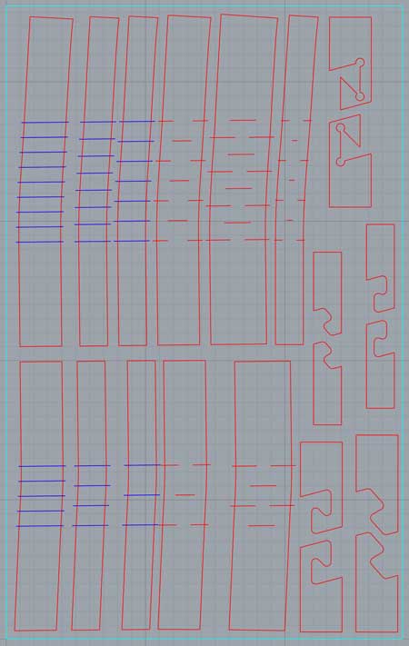
I am testing the bending of the material with a scored kerf and a through cut kerf with band thicknesses of 20, 30 and 40mm. And I have two types of custom joints with two thicknesses of band. The blue lines are scoring with a 3mm endmill and red cuts with a 6mm endmill.
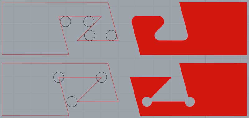
The cutting endmill is 6mm. This means any angle less than 180 degrees will have a 3mm radius fillet. Especially when designing connections, either draw with the fillet, or remove extra material behind the angles. Also, be mindful of the movement of the endmill. Any gap less than 6mm wide cannot be cut with a 6mm endmill. This is further dependent on the machine tolerances.
The kerf patterns are drawn with the intention that the mill is centered on the lines. Each space with a cut will be a flexible section of material while the spaces between the cuts will remain inflexible. To be considered is how deep the cuts, how segmented the bent appearance and how visible the grooves as they are bent, they widen. For quickly generating variations to be tested, I setup a simple grasshopper graph which additionally helped compensate for the slight directional changes that occur through the bending zones in this version of the overall design.
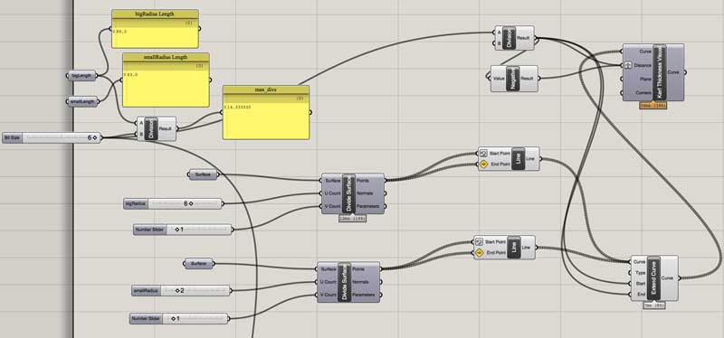
When organizing the pieces for cutting, tool path diameter needs to be accounted. I setup a simple grasshopper graph to help visualize this as I organized the pieces. And I varied distances between the pieces some to see how that would effect the machining. This is not exact. The tool will generally be moving between the green and red lines.

Now export the lines as an DXF for the CAM application. The Tongji shop requires me to use their CAM application, Type 3, which is inconvenient because it is Chinese language and can only be used by a lab assistant. After initially having file compatibility problems, I found exporting as an R12 Natural DXF from Rhinoceros works well.

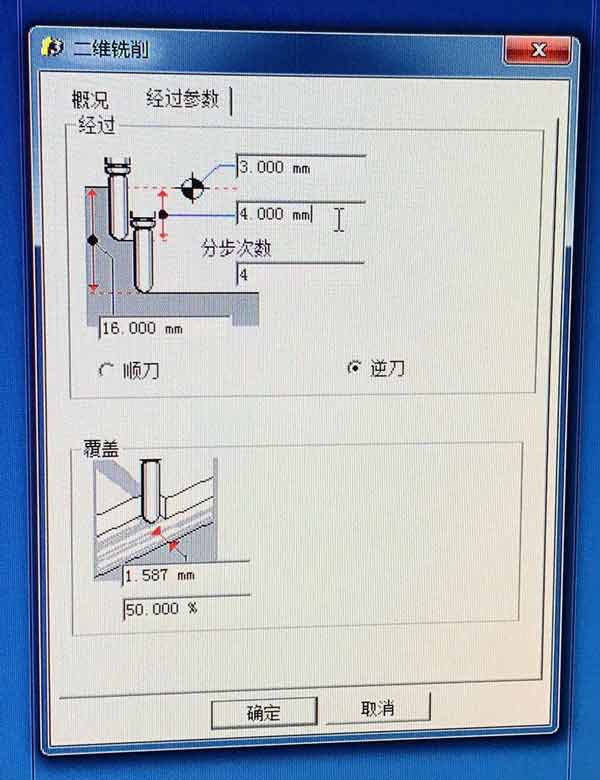
Open Type3. Import the DXF and start making the tool paths. This file will be separated into three jobs. One for the scored kerf, a second for the full cut kerf and finally the outlines. The ordering is critical for loading the machines into the mill and for minimizing movement of parts between cuts. First I created a file to cut the outlines. This dialogue sets the total material thickness, the 6mm endmill and the type of job: orientating the mill along the outside edge of the outlines.
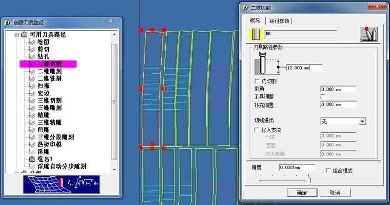
This second tab sets the depth of each cut. 6mm for two passes.
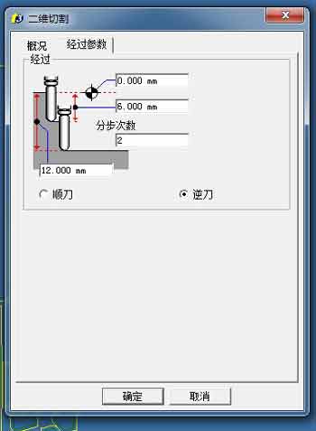
The other type of job requires the endmill to be centered on the lines. In the second tab the depth is set to 7.5mm for the score and 12mm for the full cut kerf.

After the cuts are prepared, compile the code that dictates the movements to the mill. Select this option from the right click menu of each job. The lab technician was unable to show me how to make tabs in Type3. Tabs hold the pieces in place throughout the cutting and then are small enough to easily be removed with wood carving tools afterwards. I will attempt this job without tabs and that is a huge concern.

Set the file name in the top zone. Then press the bottom highlighted button first succeed by button in the middle. This generates the G code.

With a plugin, G code can be viewed in brackets, or other applications that will not impact the file type.

The mill is a Woodpecker, produced by a Chinese company in Shanghai.

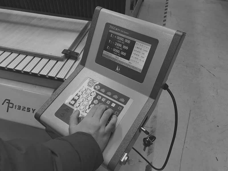
First I clamped the material to the mill and set the XYZ zero manually from the connected terminal. The Z is set to the top of the material surface.
Straight away, in addition to the lack of tabs, I had concerns with the amount of bowing in the material and the fact it is not screwed into the safety substrate. True to form, this caused problems milling so in the future I will always screw the board to the substrate. When a file is loaded into the terminal, the toolpaths are visualized for confirmation.

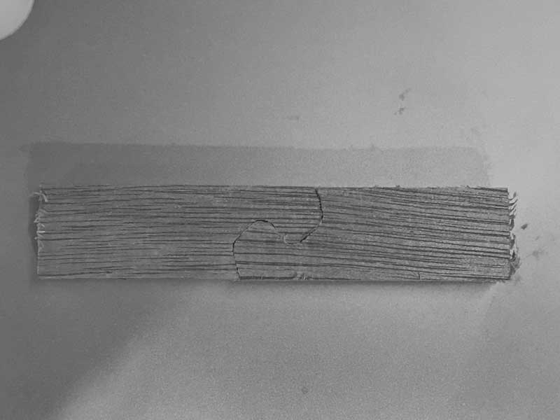
The first series of cuts are 7.5mm scores. Unfortunately, the fear of not screwing down the plywood immediately became a problem. Many of the scores went through the 10mm plywood. Further, the 6mm bit is too big for the size I need in the design. Visually, the cuts are too wide and in most of the resultant cuts the material simply broke when testing bending.

Next, along with the problem of the bowing in the plywood, the lack of tabs resulted in pieces flying around mid-job. No bueno, hombre. I cannot confidently say the tabs would have made a big difference on this particular job because the plywood was not screwed down. It is clear, though, that tabs are necessary. This is a language barrier that will need to be overcome before the next trial. Following are some brutal photos.


I kept the machine running because there were always unfinished parts that I hoped might be salvaged and it was so difficult just to get to the point of using the mill between schedule and language challenges. For the most part, well, as you can see, here is the whole bloody affair in one photo.

In the end I did get some effective joints and a piece of bendable kerf pattern. So along with improving the setup procedures, I do have some design feedback. I would like to try to gain access to a smaller endmill for the kerfing. I will widen the bands in the design and the joints could work as designed, but I will test some iteration.

This job is too tricky for the accessibility of this machine. I need to do loads of little experiments to get all the settings in place. I think this is a good start to an interesting little design, so I would like to see it through. I will follow Neil's advice in the review, laser cut a mockup first, find what can work and modify digitally, then test small pieces on the mill, modify digitally, and finally cut the first version on the mill. So, this is to be continued in another fab academy.
I will post links to resources I have found helpful here.
Bioelectrochemistry : grow module frame
For my final work, Pure Imagination, I would like to use 2 dimensional milling to cut a wood frame to carry the concrete grow modules and hide the electronics. There will be a small cut-out on one side for an LCD which will be displaying data coming from sensors across the system.
The concrete casting process was not precise due to some flexure in the walls of the mold. Each module has an extra 4-5mm total width in both directions. So the first part of making the frame was to compensate for this error. I should note, I kind of like the little bit of error in the concrete, I think it gives the modules a little character and it is the reason I did not seek to reinforce the walls of the mold.
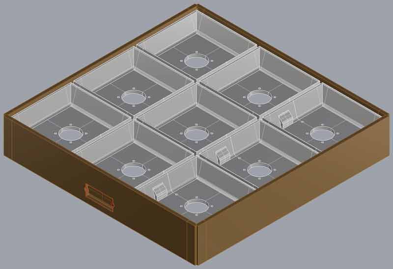
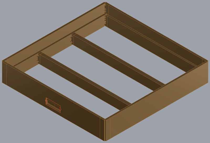
There are two types of joints, both of which I want to keep hidden. The rails catch a groove I designed into the base of the modules and there is not a crossing piece because of space required for electrical wires. I hope it is rigid without the opposite direction of ribs. The overall size is 484mm x 484mm.
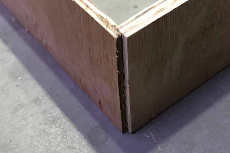
For the joints, I modified Secret Finger Tenons for the corners and the T joints were Throughole Finger Tenons. The graphic came from this ITP Fabrication post.

I redrew these joints for my plywood thickness: 14mm overall, 7mm in the upper half. From the outside, these will be invisible.
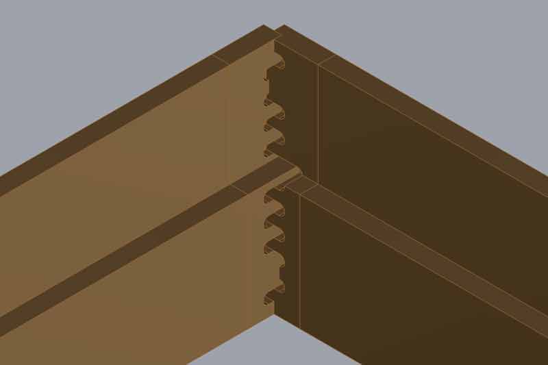
The T-joint was simplified for a smaller adjoining section of material and so that it does not go through the depth of the stock (invisible on the opposite side).

On the flipside of one of the outer pieces of frame, I will cut a pocket for a Lumex LCD module.

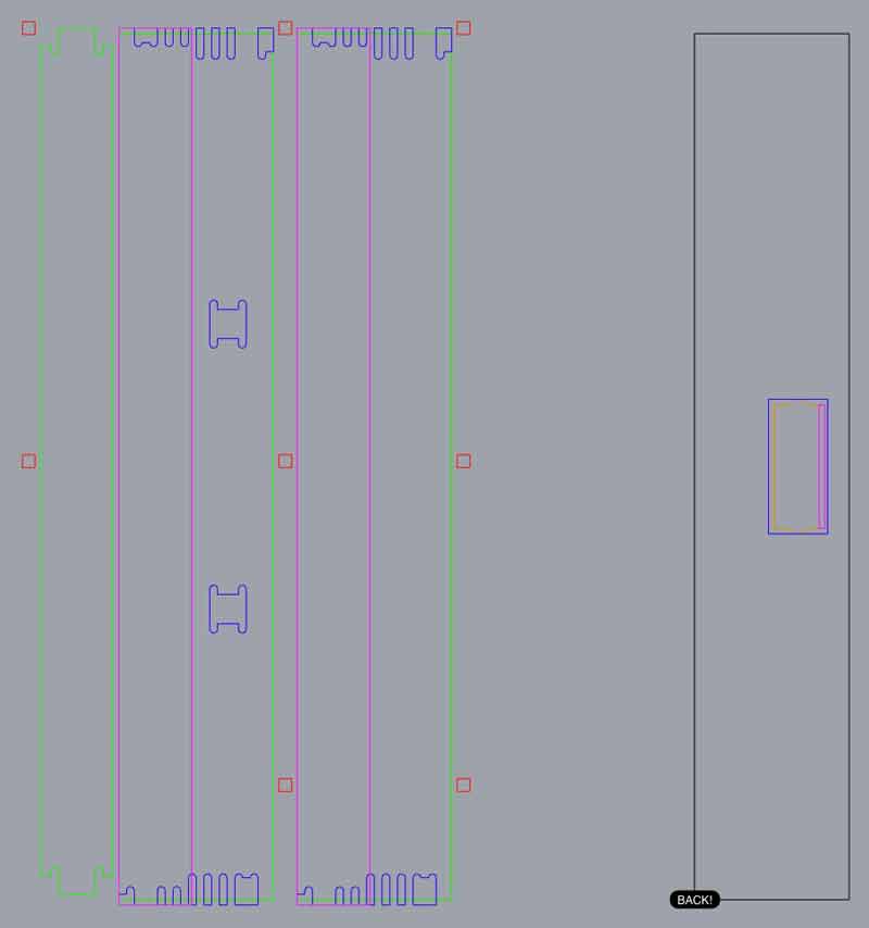
These are the cut lines. The Purple rectangles are 7mm pockets. The Blue zones are 10mm pockets. The green lines cut all the way through. And, the first job will be the red circles, just barely cut into the material in order to mark safe locations to screw the stock to the table. The blue and green lines need to be cut with a 4mm or smaller endmill. (The black circles are some existing holes in my plywood I want to avoid.)
First I cut the slight pockets to mark the safe screw hole locations. This way, I ensured the stock was tight to the table around the toolpaths, which vary in depth. No toolpaths should go through the stock unless intended.

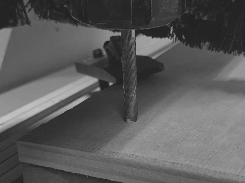
Be careful to check the tool often for too much cut material.

After cutting the pockets for the upper half of the walls, I switched from a 6mm to 3.165mm endmill.

The third cut was the pockets for the connections between pieces and finally the outlines. I added 10mm x 5mm dogbones every 300mm which worked very well to keep the pieces together throughout the cut. After, it was not difficult to remove the three pieces.
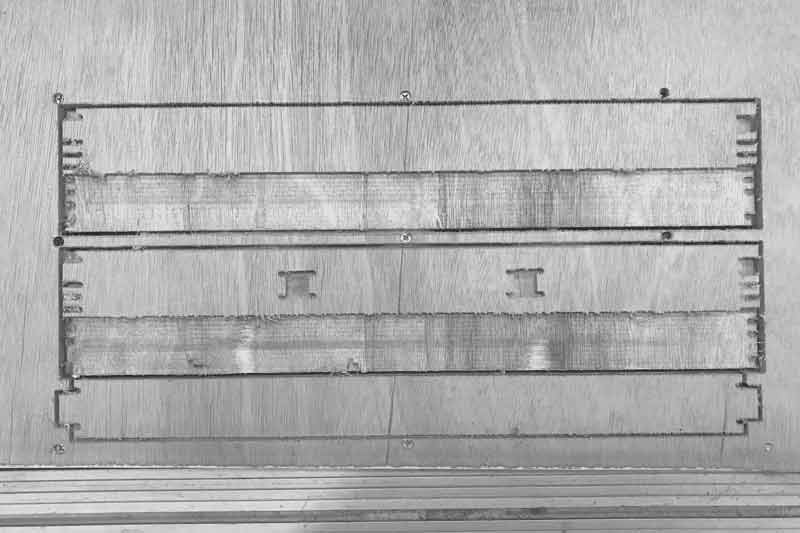
All the joints worked as designed and the cuts went much better than my first try on this machine. I intentfully left extra space on the back side of the joints just to be certain the connections would work fully on the first try.

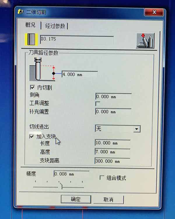
In Type3, this setting is used to make dogbones. The first of the three options is width, followed by height and finally distance between each. Bear in mind, the second setting is the total planned cutting depth plus dogbone height. For instance, -16mm cutting depth plus 7mm dogbone means -11mm to the top of the dobbone. This may be a factor if the total cutting depth is set slightly below the material thickness.
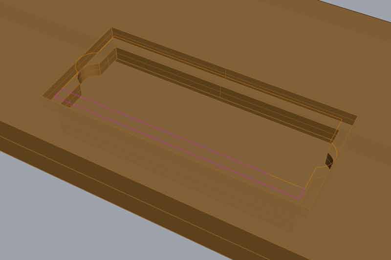
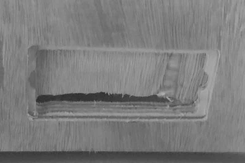
Next I flipped the wall without joints for the ribs and cut an pocket for a Lumex LCD. I added a little extra depth across the front so I can add a small laser cut piece of trim to conceal the circuit board behind the screen.

When I tested the LCD panel, I found the 1x pin header I soldered to the back of it was every so slightly throwing off the rotation of the LCD. With a dremel, I roughly fixed the wire opening. Looks like crap but will never be seen by anyone beyond this blog.
After this success, I cut three more identical pieces with the same gCode files for the other half of the box (no additional LCD).
After day one, I started looking through the gCode and found that some of the heights in the pockets were off by +3mm. When I returned to the lab, I found a setting in the Type3 software that was causing the problem. The zRef was set to 3mm. All my cutting depths were set to my depth input plus 3mm. Instead of using another 8 hours to recut all the pieces, I carefully used a dremel with an endmill and custom jig to fix the problems on the first three pieces I cut. The second three I fixed in the code before cutting.
The movement speeds in this lab are set from the terminal and password protected. Personally, I find this approach cumbersome and leading to a lack of education about proper movement speeds for different types of cuts, materials, etc.
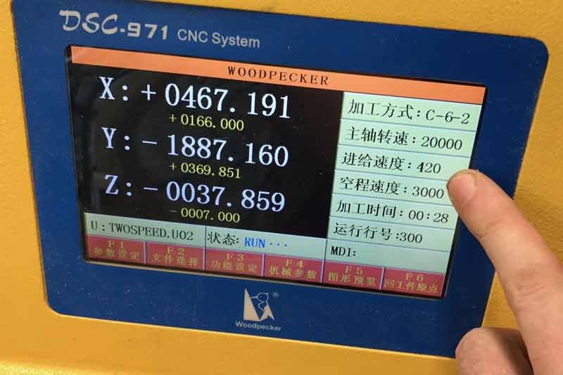
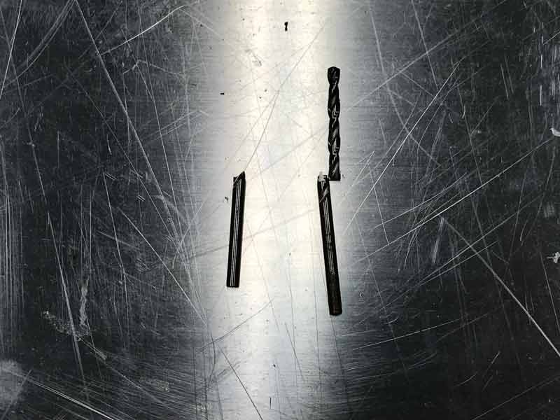
Perhaps related, two 3.165 end mills were broken. I cannot say if the setup of our job specifically caused this. At the time of both breaks the machine was cutting through 3mm depth plywood moving at 420mm per minute and for the other 300mm per minute.
Significant sanding was needed to clean up the wood at the cuts.
And, finally, the fully assembled plywood frame (no glue or fasteners). Empty it is very wobbly. Filled with the concrete grow modules, it stays true. Because the joints are hidden, they are not as strong as would be if they went all the way through the material. After building this, I would like to make adjustments and do a second version. However, using the CNC mill at Tongji is just too difficult and time consuming when working through language barriers with the lab technicians. However, it was a good experience in learning to overcome these barriers to entry to complete work. Next time I use a large format CNC machine, I hope it will be in my own language with me at the controls.

Download project files
I will post links to resources I have found helpful here.
Jump : Index
J.travis Russett © 2017
 All the work contained within is licensed under a Creative Commons Attribution-NonCommercial-ShareAlike 4.0 International (CC BY-NC-SA 4.0) License
You may remix, tweak, and build upon my work non-commercially, as long as you credit me and license your new creations under the identical terms.