Until 22 Feb 2017
Yay!
Electronics Production
Contents
- Covering Basics in Electronic Production!
- Andy: FabISP
- Progamming
- 4th The Fab Academy meeting
Covering Basics in Electronic Production!
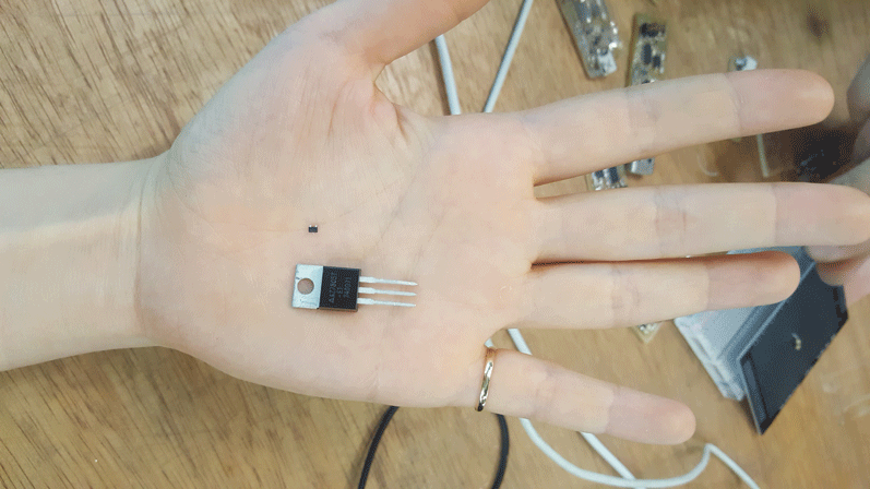
Scale of components
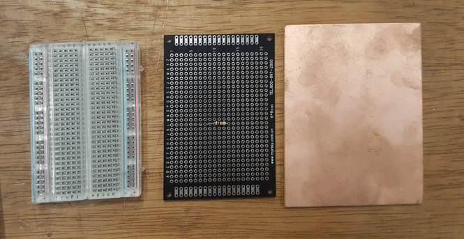
Type of boards
Breadboard - Through hole board - SMD(Surface Mounted Device)
Through hole board has limit with fixed size of the holes, so SMD transistor let us make prototypes with smaller size and sort of permanent placement.
Andy: FabISP(in-system programmer)
Preparing File
link to Andy
Original Version 2.3 FabISPkey
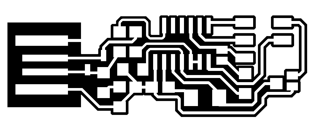
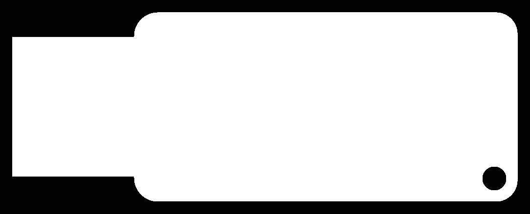
link to Fab Modules: preparing files for SRM-20 Roland Modela
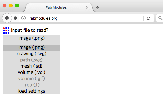
Open your image file.
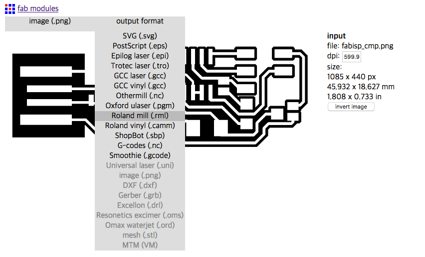
Select your output format

Change your PCB traces settings. Speed(mm/s): new 3, used 4. Number of offsets could be -1 to fill, but 4 is enough. Cut depth is 0.1, because copper is 0.1mm.

Change your PCB outline settings, Speed (mm/s): 0.5 much slower than trace setting. Number of offsets: 1.
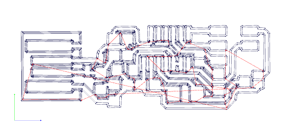
Click Calculate. if you are happy with the result, than hit save!
Mill my own circuit board
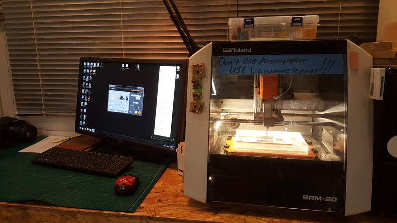
Upload your file to the computer and this case open up VPanel for SRM-20.
* Use double sided tape on the bottom of copper board without bubbles or overlapping tape.
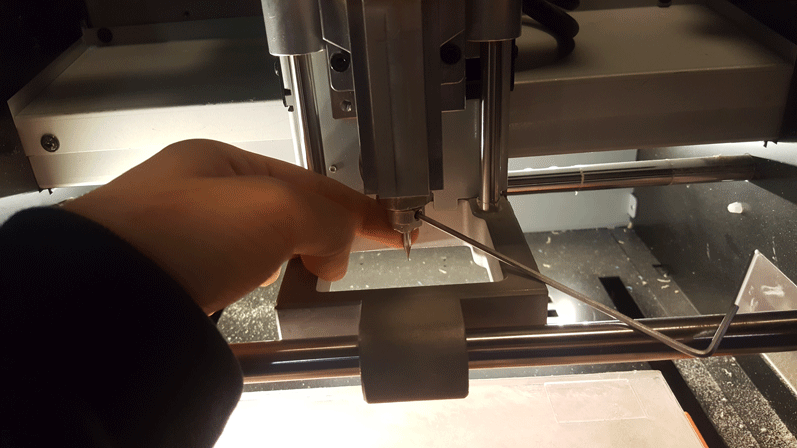
Make sure to warm-up the machine by clicking spindle on button and wait for 5~10 mins.
Replace the end mill for PCB trace(1/64) and make sure that it is tightly screwed.
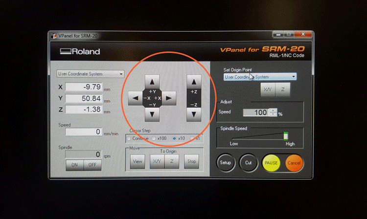
Carefully move the end mill to set up origins for x/y and z. Use x100 and x10 cursor steps for z axis.
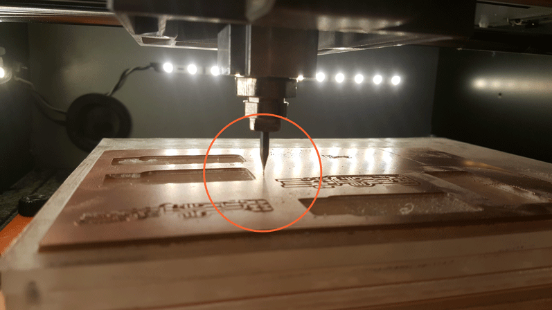
Place the end mill just barely touching the surface. You could see if through the shadows.
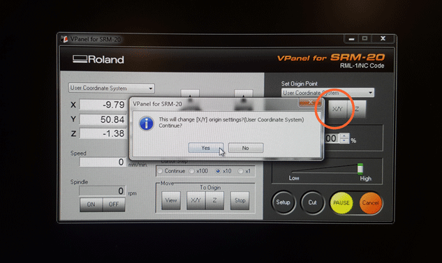
Set origin x/y position.
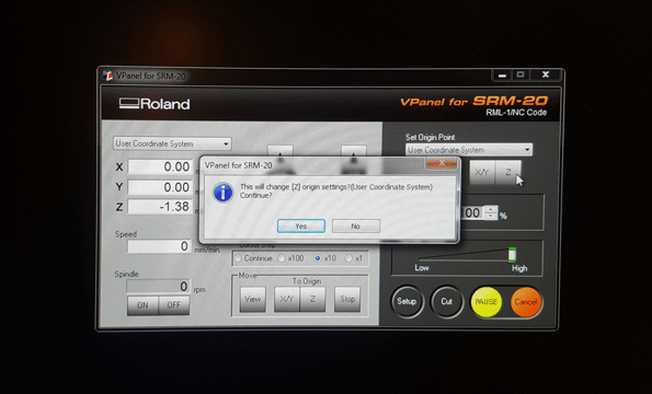
Set origin z position.
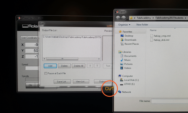
Click cut, add your output file, than finally click output.
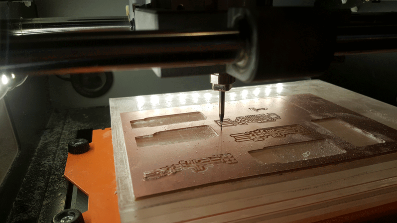
After cutting trace, Change the end mill to PCB outline(1/32). Before you start cutting outline, RESET your z axis.
DON'T CHANGE X and Y!
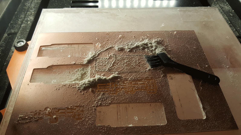
Pick up your PCB and vacumme!
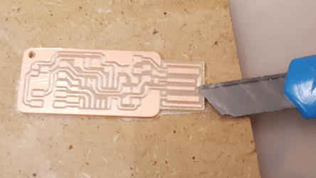
Clean up! If you have any additional copper left, cut it out with xacto knife.
Fails
1. Z axis were to low. It cut too deep, looks too 3D, and some parts were disconnected.
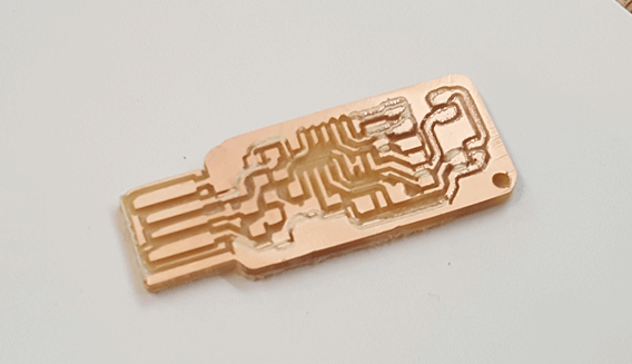
2. I didn't change the z level before cutting the outline, so I end-up cutting too deep. If it went deeper, it will cut with the cone shape of the end-mill, and messup the lines.
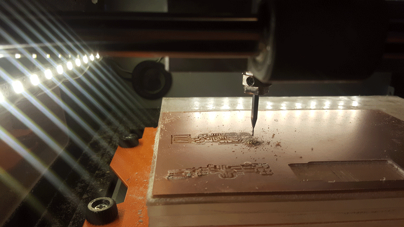
3. I've started cutting outline first.
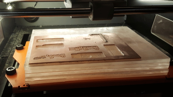
Preparing Materials
I couldn't find material list and I didn't know how to read schematic diagram, so this process felt like a puzzle.
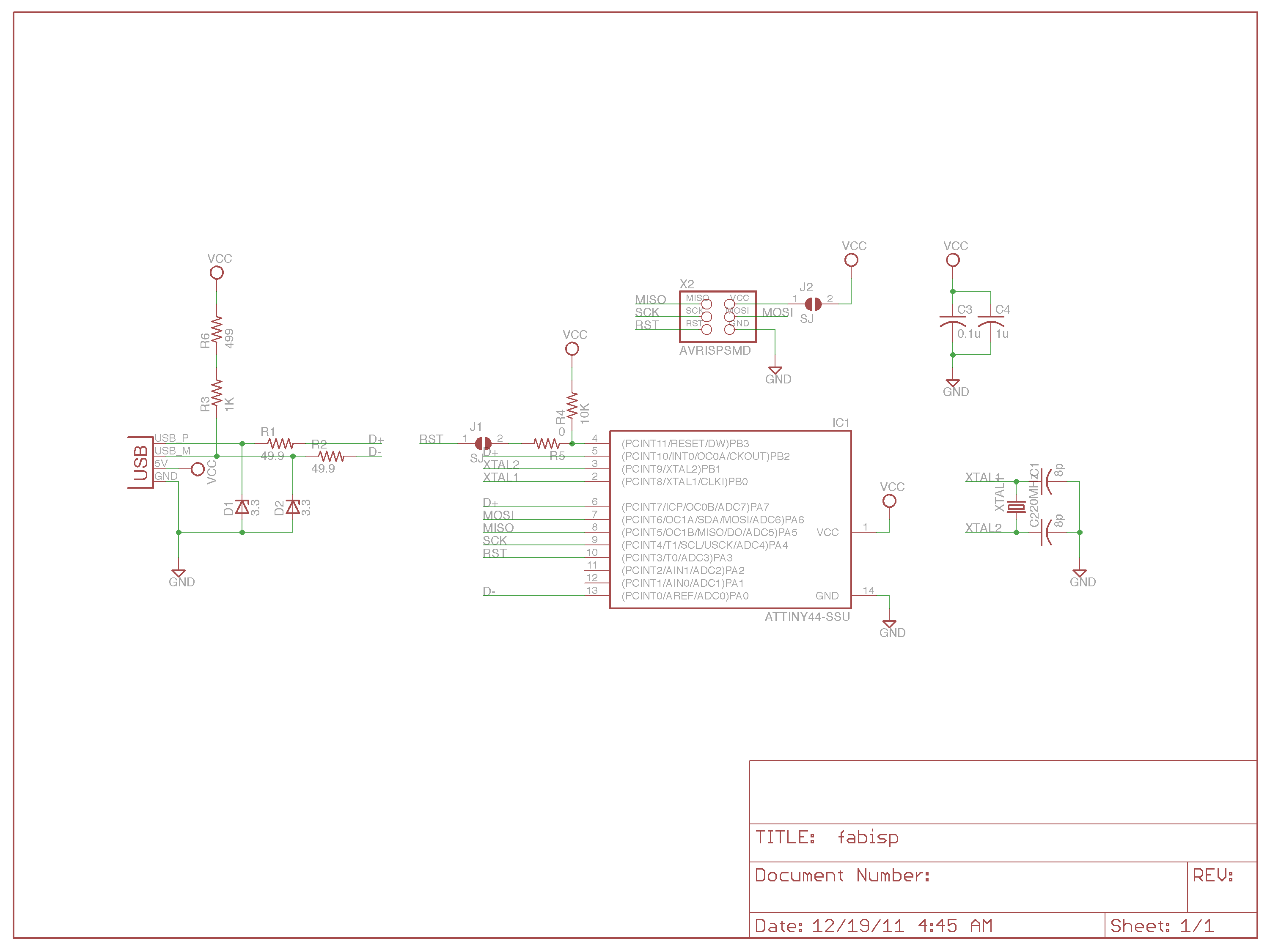
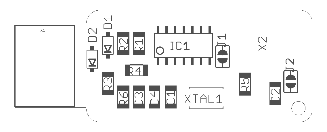
- Diode Zender 3.3v 500MW(2)
- XTAL 20MHz(1)
- CAP 10PF(2)
- CAP 0.1u/100mF(1)
- CAP 1u(1)
- ATTINY 44-SSU
- RES 10k OHM(1)
- RES 499 OHM(1)
- RES 4.99 OHM(2)
- RES 1k OHM(1)
- AVRISP SMD- male connectors(6)
- RES 0.0k OHM(1)

Solder
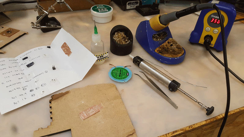
Solder from inside to outside, more complicated to less, and bigger and more bulky to small components.
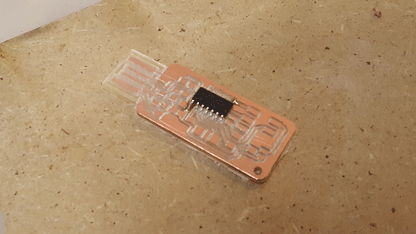
Original
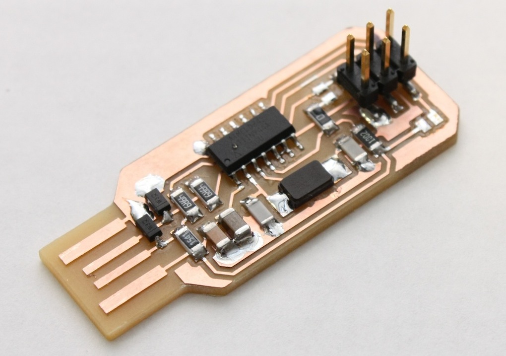
It's doesn't look identical with the original PCB.
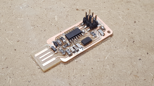
After desoldering the jumper, I realized that my FabISP wasn't registering to the computer. So I have to make new ISP.
ERRORS ERRORS AND ERRORS!!!!
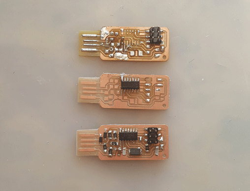
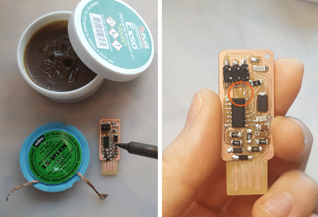
I've tried to reuse components from my original board to my last board. The middle ISP, I pulled copper out of the plate so I made new one. For some reason I ended up making three of this type FabISP and non of it worked. I tried to decode hardware problems and possible software issues. I was able to program it but it doen't register to my computer as ISP.
I gave up. I found another ISP to try. I wanted to have mini USB connector and ATtiny 44. So I tried FabOptimus v.1. At this point I already designed, produced, and programmed working 'Hello Kuri Board' for week 6. I made the board, programed, but still didn't register. Edu tried to help me, but ISP just didn't work. In Fab Lab Seoul, three of us tried this ISP and non of them succeed. I don't know what the problem is.
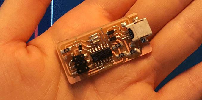
We even looked at all the components with SMD tester to make sure everything works.
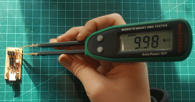
So he suggest different ISP, so I made another FabISP! One that he knows that works.
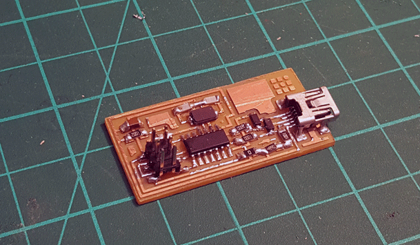
After making this ISP, of course I was able to program, but it didn't register right away. Reason was not enough solder, so after adding more solder by Edu, computer registered my ISP! Another silly thing that I forget is to remove the jumper. After removing jumper, I was able to program my Hello Kuri board. It took me a month to make a working, programable FabISP:)

Programming
Smoke test! Plug it in and if it smokes/heat-up = PROBLEM/Shortage!
Here is the link to see the procedure, with the help of our Seoul Guru! I was able to make my first FabISP.
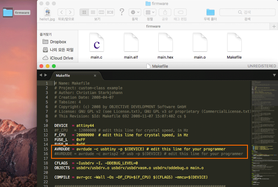
Since Andy was made base on ‘Neil's FabISP is based on David Mellis's FabISP which is based on Limor's USBTinyISP which is based on Dick Streefland's USBTiny.’ First, I’ve downloaded David’s Firmware, but I ended up using the firmware.zip from the academy’s electronics production link.
After downloading I’ve made one change in Makefile.
Connect your ISP with programed ISP.
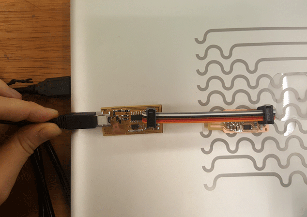
Program
Make Clean

Make Hex
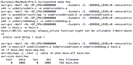
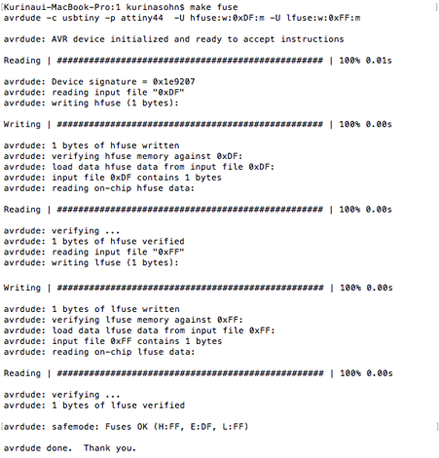
Make Fuse
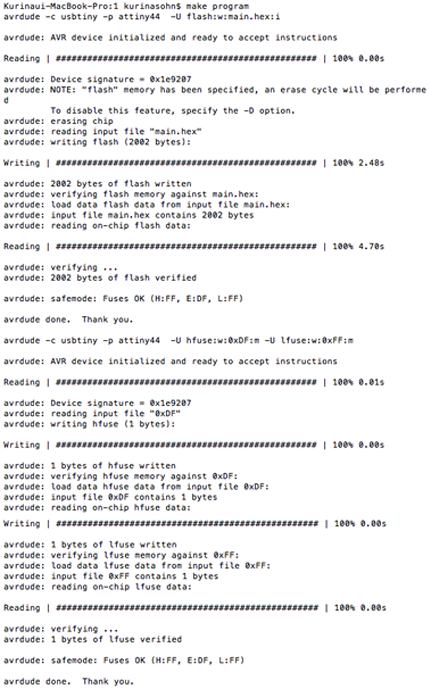
Make Program
Make sure that computer register new ISP.
ERRORS
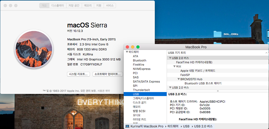
This error kept showing!

I had to resolder the reversed diodes and short in circuit.
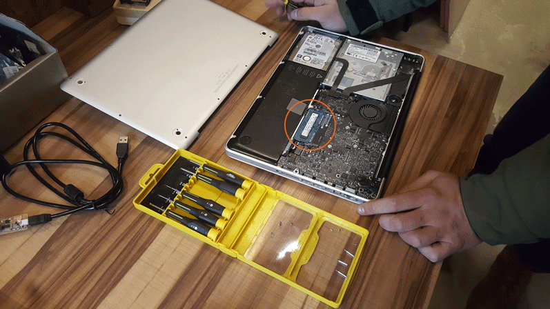
After solving hardware problem, I still had the same error shown on my screen. I reinstalled CrossPack, Xcode and restart my computer. My computer slow down and I wasn't able to complete programming, so I ended up upgraded the RAM. After that I've used OnyX to Clean my computer. My computer is faster now:)
4rd Meeting:
Electronics Production February 15, 2017 11pm~2am(Seoul)
Homework
Make an in-circuit programmer by milling the PCB, then optionally trying other processes.
o- Shown how you made the board
o- Explained any problems and how you fixed them
o- Included a ‘hero shot’ of your board
o- Program
