One of the real challenge of this machine was the tool. Every CNC machine works the same, it is the tool that defines this machine. In our case it was the tufting tool. This tool must move up and down at a certain speed in order to penetrate the fabric just as fast enough to put the thread and not shred the fabric. This speed also must be coordinated with the X axis movement.


First we design a model in the software Solid Works. We used this software because it's really professional for creating ensembles, and it also has a lot of simulation modules so we can make it work to test the up and down movement before we manufacture it. It is also easier to use than other professional softwares like Catia.
The trick for the up and down movement is a cam and gears. This was design in order to solve some of the issues of the tool.
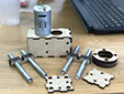
The Cam serves the purpose of transforming the rotational movement generated by the DC motor into a linear movement. The function is explained in the picture. The axis rotates, rotating the cam, every turn of the dc motor the cam will push down the follower which in this case is the needle for the tufting.
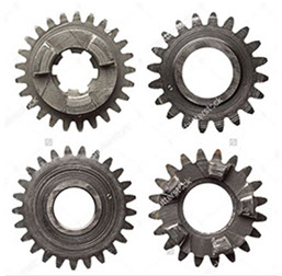
The gears were added to the design so we can slow down the spin speed of the DC motor. Our motors spins so fast that the needle and the fabric may break. We calculated our gears to slow down the motor and gives us the necessary speed to tuft the fabric.
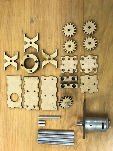
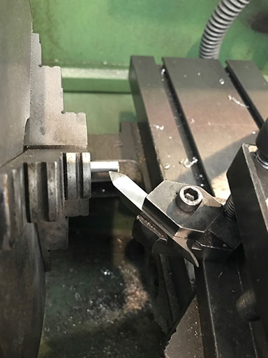
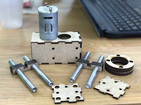
Once our design was ready we decided to prototype it using our laser cutter. This was the fastest option and the more precise for the gears, the cam and other elements. The needle was manufactured in a diferent way using our lathe.
The elements were cut in the laser cutter. Someof the elements needed more thickness than the one provided by our material. 3mm MDF, so we cut multiple times that element and glued them together to gain the thickness that we were looking for. For the metal profiles we used some aluminum pipes that we have in our waste basket and we used the lathe to gave them the 1/8 rope.
.jpg?crc=4164925271)
.jpg?crc=431827750)
.jpg?crc=514162143)
.jpg?crc=186624811)
-crop-u4787.jpg?crc=177223577)

-crop-u4785.jpg?crc=4073890429)


-crop-u4793.jpg?crc=159514231)
114x85.jpg?crc=4051389169)