Final Project - Manufacturing mechanics
This page gives details of making some of the parts for the final project. General presenting of the final project can be found from the Final project page.
Vertical and lateral mover unit building and assembly
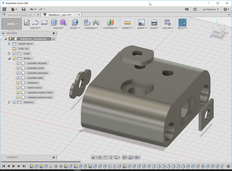
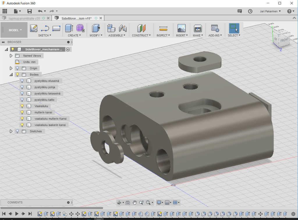
I designed the whole mover unit in Fusion 360. Here is a picture of it. This image does not show the servo arm that will be explained later on the page.
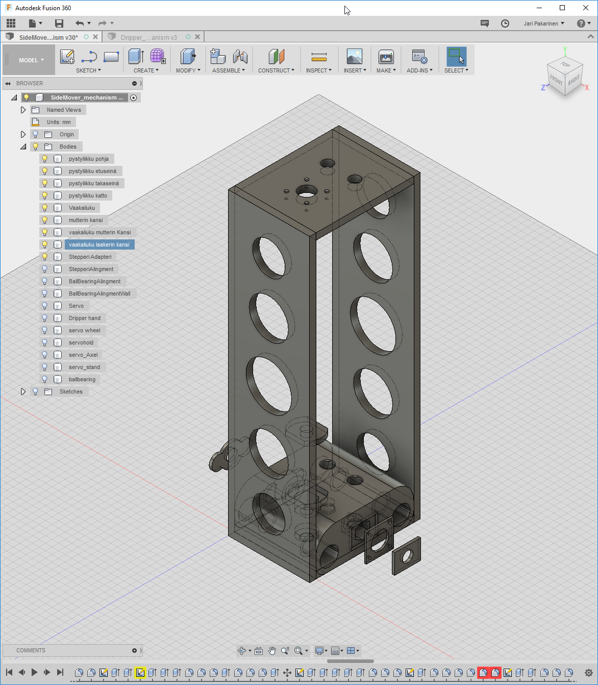
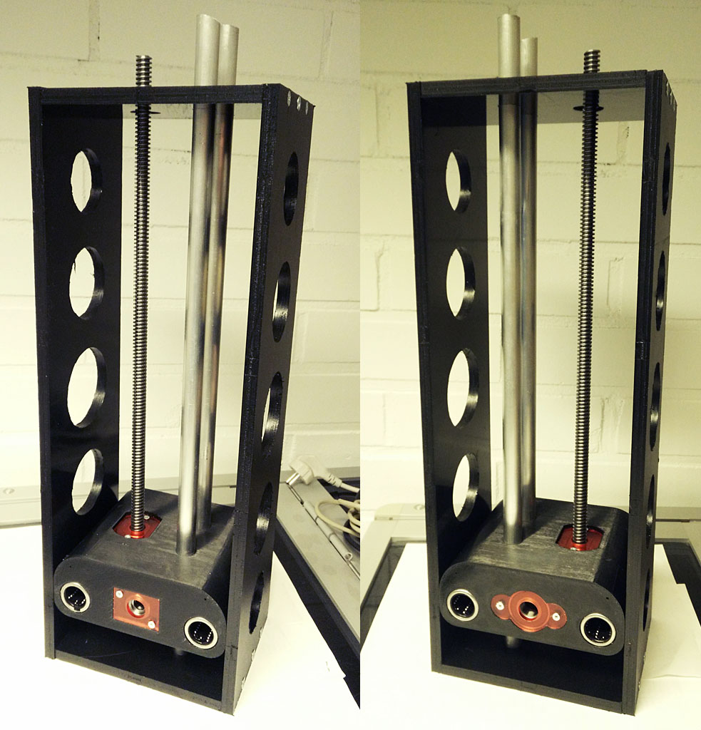
Vertical mover unit
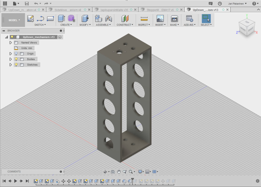
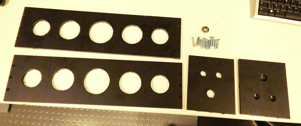
The part that moves up and down and dips the pcb in the tank looks like this.
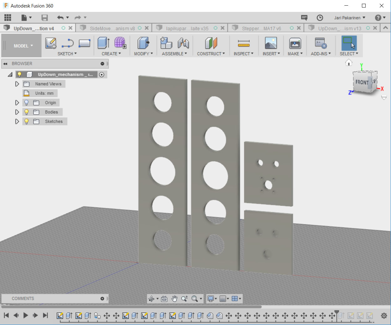
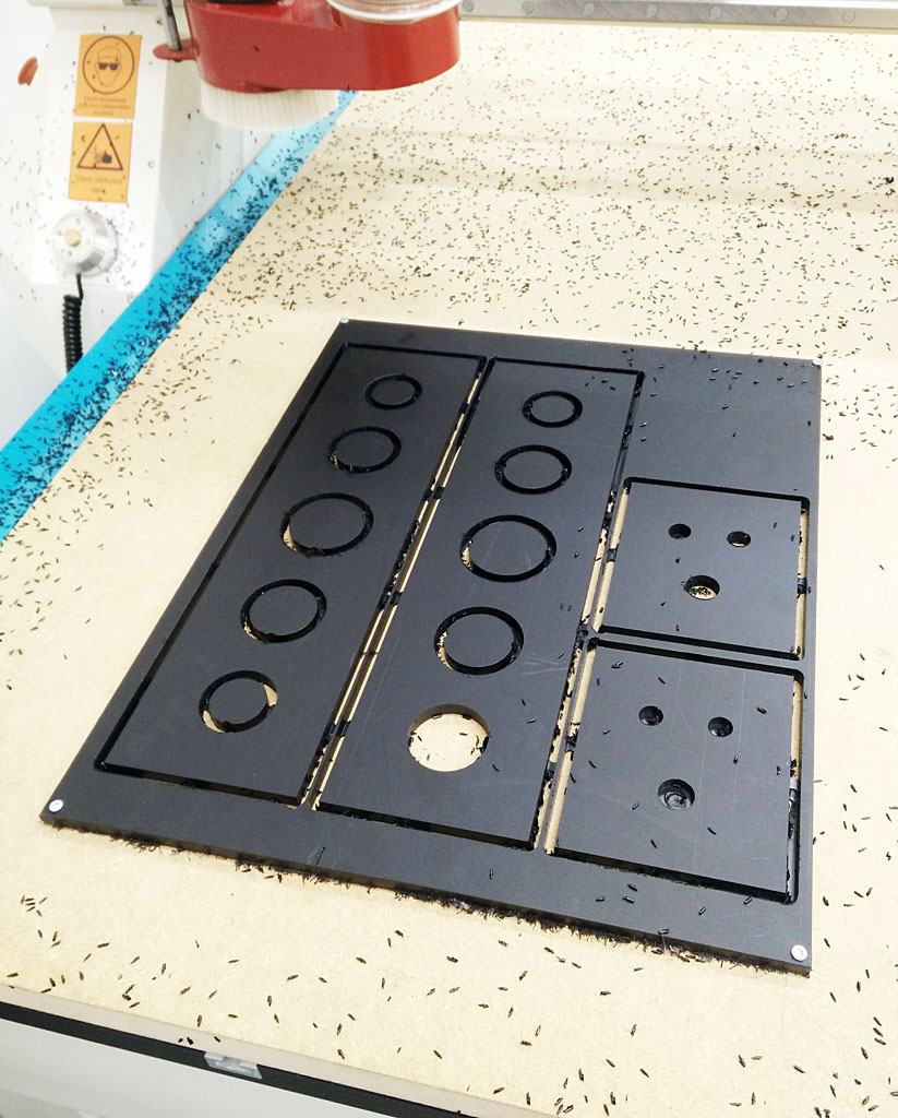
For cutting them out from plactic plate with our big milling machine. I arranged them in one plane and made the milling files. There is one pocket milling, one inside part cut and one outside cut file. In post prosessing I combined them into one file so the milling would go smoothly. Files can be found at the end of the page.
Milling tracks can be seen on this picture.
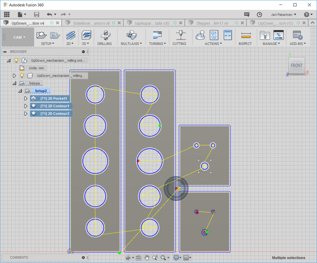
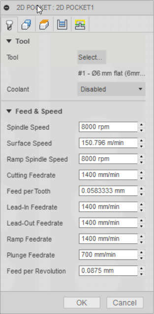
For milling I used 6mm flat head mill bit and these setting. Other setting are more general and can be seen on weekly assignments.
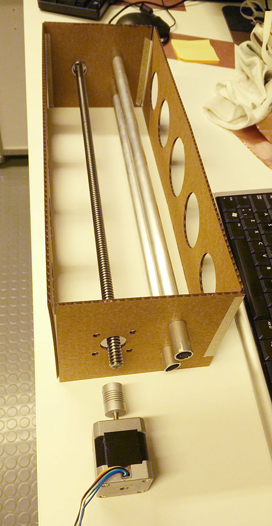
I also laser cut these parts out of cardboard just to see if they would fit with other parts. This is a good way to see if something is measured or arranged wrongly. Pieces fit well to gether.
Here I am cutting the parts out with our big milling machine. It was used at week 7 and procedures to operate the machine is documented there.
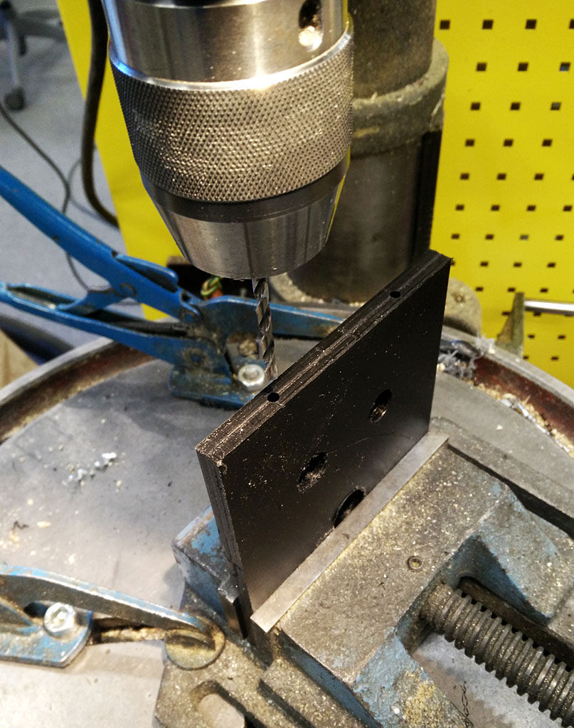
I had to make some manual drilling for screw holes with a drill.
Ready mover unit assemply
Part for the vertical movement structure are ready here.
Lateral mover unit
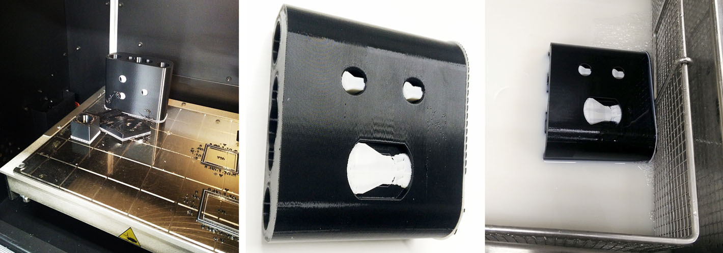
After 3D designing the parts I printed the main slide part with our labs Stratasys printer. It is nice and easy process as you just slice the part and send it to the printer for printing and collect it next day. Only problem I had was removing the support material (white on the pictures). We have a tank full of sodium hydroxide to melt the support away. For my surprise my part did not sink, it was only floating on the surface. After having it in the tank for some time, I desided to use piece of metal (steel) rod to sink the part. This worked fine but it still needs over 24 hours for the support material to dissolve. And after the path, the part is partly filled with the sodium hydroxide. It would take days for it to leak out from the part. I good tip from a friend was to drill couple small holes to the structure for the material to leak out. After that and couple of days waiting the sodium hydroxide was out and part was ready for assembly.
Here is some pictures of the printing.
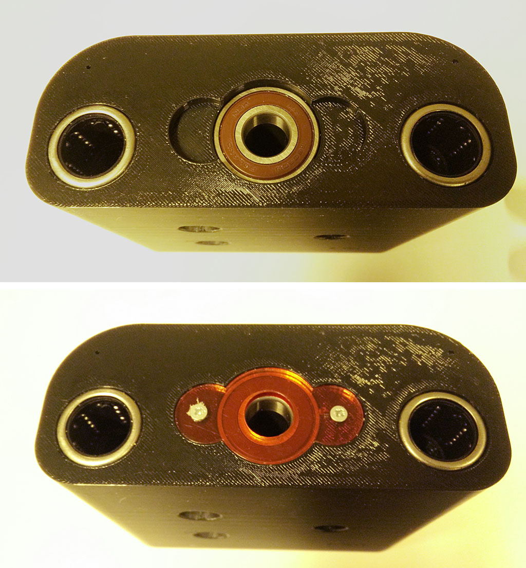
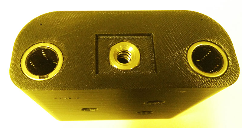
The lateral slider part is the center of the moving structure, it houses the vertical slider structure and the carries the pcb. Here are the parts manufactured and assempled. First image has the lateral slider part and all supporting parts for it including ball bearings and covers.
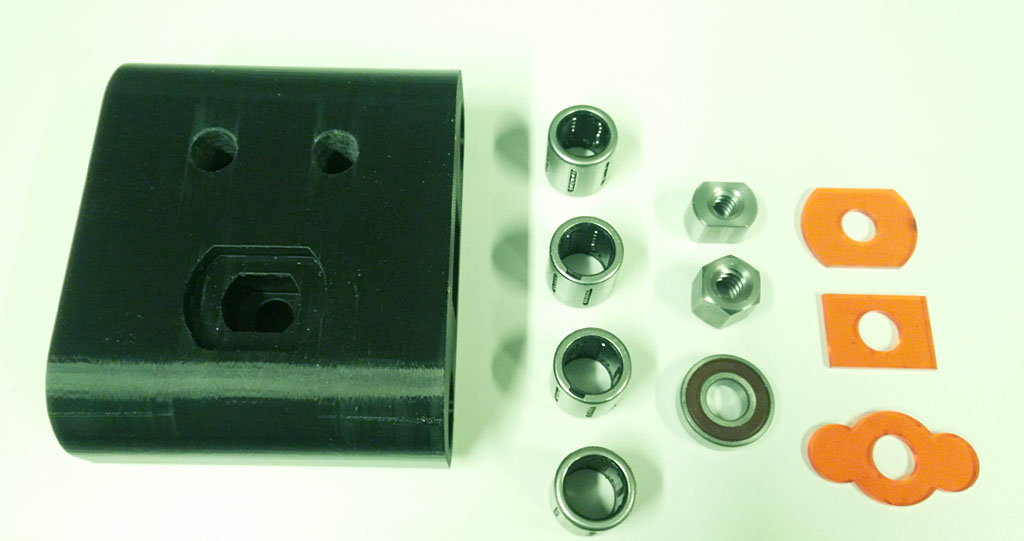
Bearing housings and nut housings have covers laser cut from acryle. Even the parts fit in nice and tight, the covers make sure that they stay in place.
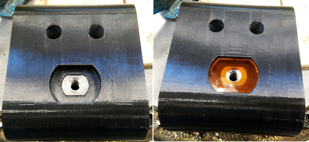
Here is the main lateral slider and the vertical mover structure assempled and ready to be attached to the lateral slides.
Main lateral slide block .stl file
Main lateral slide block nut cover .stl file
Main lateral slide block ball bearing cover .stl file
Main lateral slide block vertical nut cover .stl file
Main lateral slide covers laser cut .pdf file
Main vertical slide parts mill files .nc file
Main vertical slide parts mockup laser cut .pdf file