Computer-Controlled Cutting

Assignment:
Group Assignment: make lasercutter test part(s), varying cutting settings and slot dimensions
Individual Assignment: cut something on the vinylcutter design, make, and document a parametric press-fit construction kit, accounting for the lasercutter kerf, which can be assembled in multiple ways
Work
This is for me, one of the important machine I want to learn for my future. Before all my work I need to kwon how Epilog Helix Laser Cutter works, and his most important funcion; Pros and Cons of laser cutting. For the First the laser must be prepared before send the file and start to cut whatever we want.
I use the both Default Epilog software used for laser cutting; and Visicut Software. Visicut is an open source software, and it can be downloaded at: this link
Visicut must be configured with the Epilog Helix Laser cut configurations; and what kind of material we want to cut(for the first Test we use cardbouard of 6mm) Visicut has this kind of user interface; and the mosts important parameters we must sets are: Frequency,the Power, and the Speed of the Laser. When we open Visicut we have this interface:

For the Firsts test I use cardboard, we set tollerance to zero; that means the thikness of the cardboard is 6mm, and we do a male and female joint with a hole of 6mm.
Test One: Power: 40 - Speed:30 - F: 500.
The cardbord was marked, but not cut. Test Thwo: Power: 60 - Speed:20 - F: 500.
The cardboard was more marked but Isn't yet cut.
You can see the the result on this picture:

On the Test 3 : We Set Power: 100 - Speed:30 - F: 500.
And the cardboard isn't yet cut. The Last Test was successful with this Parameters: Power: 100 - Speed:15 - F: 500
You can see the result on this picture:


In the group assignment we calculate also the kerf value. We Cut 9 little piece of plywood for determine how the kerf is; and how is the perameter to considerate when we cut something. The follow link show how we calculate the Kerf: Group Assignment
The Next Step For me, is to choose a Parametric software that can help me to redefine the parameters of my joint design every time i need; expecially for the joint of my snapfit presskit. The Software I Choose for my design is Fusion 360. This software is very powerful software, but It don't let me export my sketch in dxf or other file format useful for laser cutting. The file i need to generate, is a dxf extension. For this reason I found a plug-in for fusion 360, that able me to export every sketch i do, in a dxf file extension, in this way i can launch my file on the Epilog Laser. The plug in I installed on my Fusion 360 is this:

and you can find it at this address on Autodesk App Store For the Group Assignment we do different kind of test, we start to design the joint with a parametric software; The First Test of Joint is This:

and after we cut it in cardboard with laser. You Can See the different measures we set to the joint. We do also different kind of test, for testing the Power, The frequency and the Speed of the Laser.

Also we make this Joint with plywood: More information about group assignment at this link

This is a very useful Joint, and you can find other like this at this Address Also on This link
Press Fit Construction Kit:
The concept:
For my press Fit Construction Kit I decide to make an Truncated Icosahedron or simply called :Football Ball. For This Solid I do different researches, fot understand how i can contruct the trunched icosahedron once finished to cut the cardboard. I found some important informations on this website:
I must use 2 different joint, because betweek the hexagon and hexagon there's an angle of 138,2° and between pentagon and hexagon there's an angle of 142,6°.


The Design:
For the truncated icosahedron I use Fusion 360 , and I krow that I need of 12 pentagon and 20 hexagon, and I need to do two kind of joint: one with an angle of 138,2° and another with an angle of 142,6°. In Nature we can find this geometry also in this mushroom:
This Is my design and the two joint:

Also in this case the tollerance is egual to zero. I realize a parametric Design usign the contraits of Fusion 360, and If I need to increase the tollerance for the thikness of the cardboard, I only modify a parameter i need and the rest of design fits all it's form.


At the End I export the sketch of my project in dxf format in this way:

This is my Pressfit construction Kit:


And this is the result once assembled :


Download the File:
Trunched Hexagon:
The Neapolitan Amulet:
I try to use also 123Dmake, it's a very useful program for laser cutting. and i create a famous neapolitan amulet with Rhinoceros.
after I import this deign in 123Dmake for create the plan.


This the File of My Neapolitan Amulet
Bottle Holder
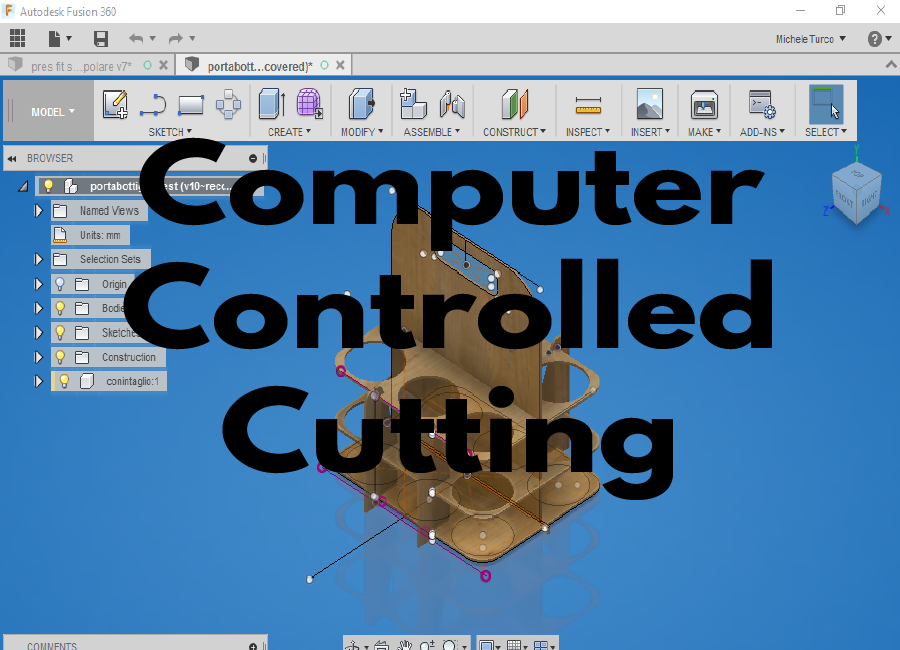
For Laser cuttig plywood i choose to design a bottle holder. Also in this case i choose to design it with fusion 360, and we use a plyeood with 3mm of thikness:


Downlad the File: Bottle Holder
Cut Something with Vinyl Cutter:
For the assignment with the vinyl cutter I decide to create an image with Adobe Illustrator and try to use Fab Moduls for generate a dot.cam file for the vinyl cutter. In Illustrator I use this image for create the vector.

This is the image I generate, and I modify it creating a big extruder on the top of the picture.


Download the File: Vesuvius Extruder
- Back to Home
- Date: 8th February
- Topic: Computer-Controlled Cutting