Juan García-Maestro Gil-Casares

FABLAB MADRID CEU


10. Output Devices


Procedure:
0. Assignment
1. Strategy
2. Material I need
3. Designing My Board - Schematic
4. Building My Board - Board Final Design
5. Milling The Board
6. Reading Atmega 328 Data Sheet + Understanding PWM
7. Programming: My Program - Creating My Program For My Final Project
8. Programming: Tests
9. Code Used
10. Problems Accounted
11. Download Files

0. Assignment


Add an output device to a microcontroller board you have designed and program it to do something.


LEARNING OUTCOMES


Demonstrate workflows used in circuit board design and fabrication.

Implement and interpret programming protocols.

HAVE YOU...


...described your design and fabrication process using words/images/screenshots

...explained the programming process/es you used and how the microcontroller helped you

...outlined problems and how you fixed them.

...included original design files and code.

1. Strategy


The goal this week is to continue developing my final project. As the project is to create a lightning device that can be moved without being touched, my idea is to create a new board connected to a stepper motor.

The reason I chose a stepper motor is because I can have a controlled movement, giving me the opportunity to measure distance (the axis I am using) with steps.

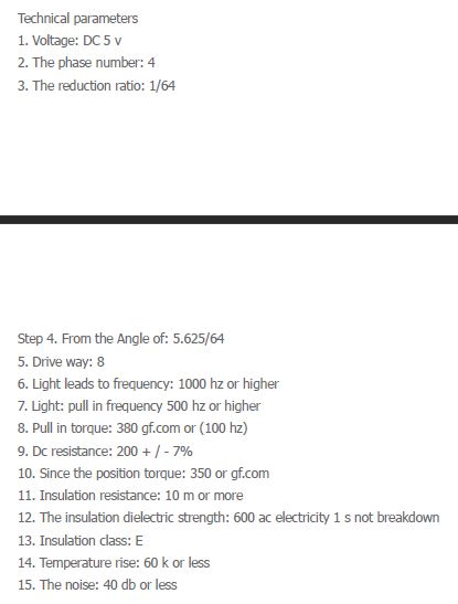
The motor I will be using is

'Stepper - 28BYJ-48':


Check Stepper Motor - Data Sheet:
Your browser does not support this image

Your browser does not support this image

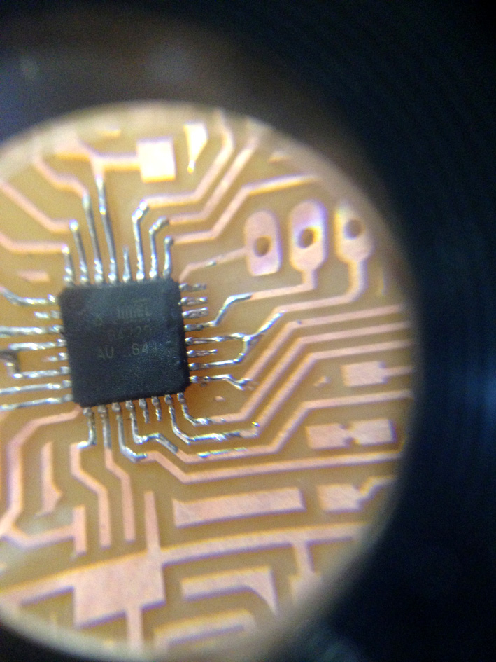
MCU I am going to use:

I will be using a Atmel AtMega 328 P with 32 pins. The reason I chose this one is because it has more memory than the ATiny 44 that Neil uses. Plus, in order to have as well a RGB led, I need more pins to connect the led.

Your browser does not support this image

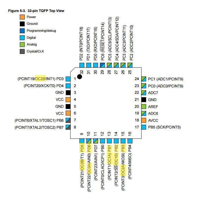
Here is the reference with arduino pins:

Your browser does not support this image

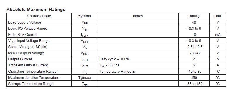
To work with a Stepper Motor, I need to H-Bridge to change the currents direction. I selected H-Bridge A4953 for my board:

Your browser does not support this image

Making sure it can support the 12 Volts that will be supplied to the stepper motor:

Your browser does not support this image

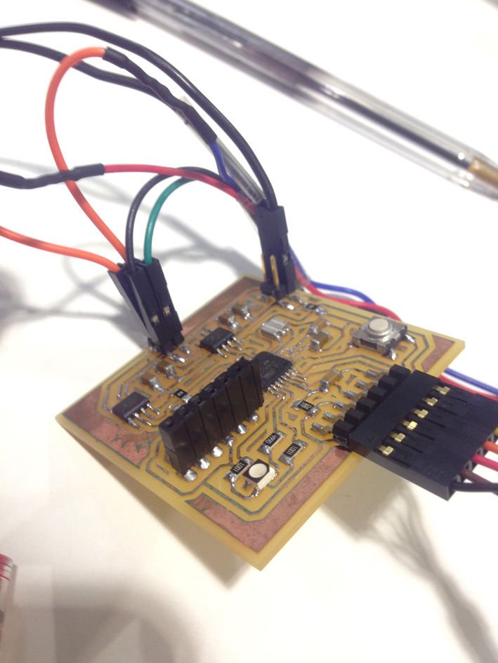
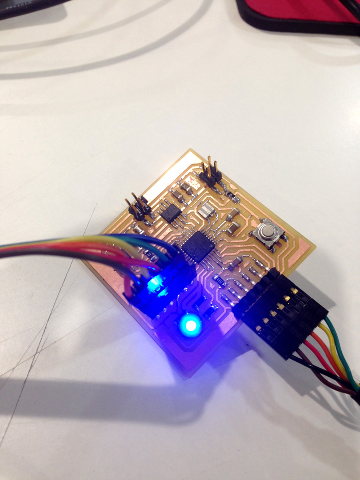
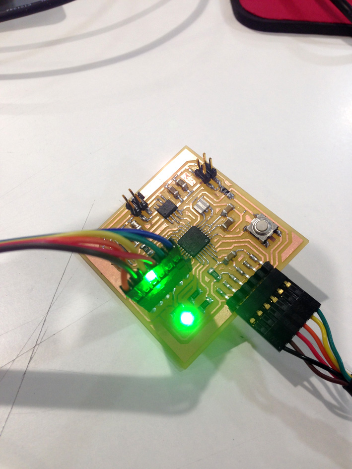
As well, it is highly recommended to have a led incorporated to the board, especially to make sure it works correctly first.

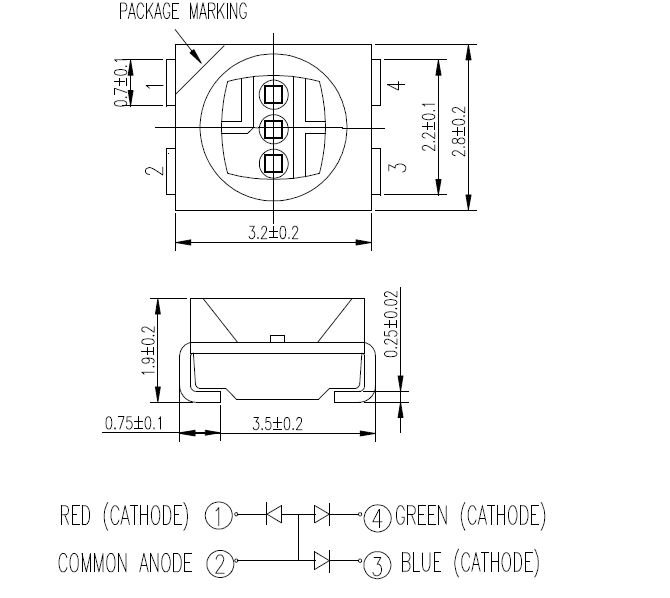
As the last 2 boards I have had an included different colour leds, this time I wanted to use a RGB led (RGB Led CLV1A-FKB)

Your browser does not support this image

Technical information


Your browser does not support this image

Your browser does not support this image

2. Material I need


-1 MCU AtMega 328 P
-2 Capacitors 0.1 uF
-2 Capacitors 1 uF
-3 Capacitors 10 uF
-1 Switch/Slide
-1 RGB Led
-1 Resistor 10k
-2 Resistor 1k
-1 Resistor 499 ohms
-3 Jumpers (0 ohms Resistor)
-One 2x2 Pin For 12 Volts Supply For Motor
-One 2x2 Pin for connection to Stepper Motor
-1 FTDI Male Connector
-1 Resonator 8MHz
-1 Female Connection Pad 1x06 (for the USBTinyISP Programmer)
-2 H-Bridge A4953

3. Designing My Board - Schematic


In order to make my board, I had a look to Fabacademy's archive and based my board on the Fabkit board and Neil's board (for Stepper Motor and RGB Led):

Your browser does not support this image


Your browser does not support this image

Your browser does not support this image

Here is my schematic of my board:

Your browser does not support this image

4. Building My Board - Board Final Design


In one hand, one big difference from the other board I have designed ('Electronic Design Assignment'), is that this time I am using a 12 volt circuit for the motor. This quantity of volts need a bigger trace in order to work correctly.

I entered the internet and entered 'Trace Width Website Calculator' to calculate the minimum width I need to have a stable electric circuit:


Your browser does not support this image

On the other hand, as I am using a MCU that has its pins closer than the ATtiny 44, I had to change the design rules on my software:

Your browser does not support this image

The space between pins is very small. With the previous design rules, all pins would have been connected together.

Final board design:


Your browser does not support this image

5. Milling The Board


As in previous situations, I have used the Modela MDX-20 to create my board. As always, I have my .PNG files (traces, perimeter, holes):

Your browser does not support this image Your browser does not support this image Your browser does not support this image

Uploading PNG files to Mods:

Your browser does not support this image

Once I positioned the mill on the correct place and checked everything was correct, SEND.

Result:


Your browser does not support this image Your browser does not support this image

When milling the board, I had several problems with mods. Although on the png file the traces are clearly separated, mods did not interpret it in the same way, having some copper without being milled. I had to change it on the png on photoshop, making the traces even smaller, but I missed some of them, as they were not as obvious as the microcontroller pins.

I had to go back to Eagle and change how I have designed the traces, go to mods and check if the machine mills correctly. It took a little while, but finally I could make it:

Your browser does not support this image

The colour yellow shows all the problematic places on the board.

Final Result:


Your browser does not support this image

Soldering the Board

Your browser does not support this image Your browser does not support this image

Your browser does not support this image

6. Atmega 328 Data Sheet + Understanding PWM


As I have a RGB Led on my board, I will need to use the PMW to make my led work as I want.

The PWM is a type of digital signal that varies between high (5V) or low(ground) at any time. The signal is made out of the duty cycle (the amount of time the signal is in a high state) and the frequency (how fast the PWM completes a cycle).

This method is used to generate analog signals from a digital source. The more duty cycle it has, the more time the signal is at a high state per cycle.

This method is used to generate analog signals from a digital source. The more duty cycle it has, the more time the signal is at a high state per cycle.

Your browser does not support this image

In order to control the duty cycle and the frequency, I need to know the information in the data sheet about the timers of my MCU.


Here is a 8-bit Timer/Counter Block Diagram of my Atmega 328:

Your browser does not support this image

The pins that can create PWM are the timer/counter pins.

7. Programming: My Program


For the output board receives through serial communication the order (FTDI cable). So, depending on the computer's order (a number), will arrive and activate the stepper motor.

The responsibility of this boards is:
-move the stepper motor so the slider moves to the direction I want to.
-as I will have a fix moving distance, know exactly at what position the slider is so it does not crash to one of the sides.

The orders the board can receive are:
-number 1
-number 2
-number 3

Moving The Stepper Motor


In order to move, I used the command 'myStepper.step(the order. This order can be:

(stopMoving)
(steps)
(-steps)

My strategy is that the motor will move the slider a certain amount of distance each time it receives a number. A non-continuous movement is caused.

My strategy is that the motor will move the slider a certain amount of distance each time it receives a number. A non-continuous movement is caused.

-'stepsPerRevolution': the number of steps the nema-14 stepper motor has are 200.
-'steps': the number of steps I want the stepper motor to do when executing the command: 60.
-'stopMoving': making sure it stops.

As well, there is another command that needs to be declared: setting the stepper motor's speed: 'myStepper.setSpeed(60). In this situation, I decided to have

Your browser does not support this image

Your browser does not support this image

(a part of the output's code, please check the full code either with the file or next chapter).

Position


To make sure the slider does not crash onto one side, the board knows exactly where the slider is positioned. To do this, I store its position every time the loop has been executed.

Previously, I have declared these variables:
-origin: constant variable with assigned value 0.
-totalDistance: after testing it, that horizontal axis has a total of 1200 steps.
-lastPosition: it stores the last position the slider was at.
-newPosition: with the number of steps, the slider knows its position.

When number 2 or 3 arrive from the master board, the slave board has the order to move when this condition takes place:
-it calculate what will be the 'newPosition'.
-if the newPosition goes beyond or under the 'totalDistance', it does not execute the command 'myStepper.step(steps)'.

(Check on the images above the code or go to next chapter to see the complete code)


8. Programming the Board


First of all, as now I have more memory, I am able to burn a bootloader. Once I installed it into MCU's memory, I will be able to upload any program without using the programmer (FabIsp). Let's check that all connection between components are OK and start burning the bootloader:

Your browser does not support this image

Adjustments needed:
-Board: Arduino Pro or Pro Mini
-Processor: Atmega 328 (3.3V, 8 Mhz)
-Port: COM 3
-Programmer: USBTinyIsp
-BURN BOOTLOADER

Your browser does not support this image

Everything OK! Now I can start programming.

Your browser does not support this image

PROGRAMMING THE BOARD - CHECKING IT WORKS CORRECTLY


To start with, instead of going directly programming the stepper motor, I created a quick program to make sure the MCU works correctly. I activated the pins connected to the RGB Led and code it to respond with the 3 different colours: Red, Green, Blue.

Explaining the 'Test Program':


First I define the different variables for each pin (as they are constant variables, I declare them as such). In my case, the red led is pin A4, the green led is A2 and the blue led is A3.

For the setup, I initialize each pin with the command 'pinMode'. I start turning on the red led, then use the command 'delay for 1000 milliseconds, turn of the red led and turn on the green led. The same process to end with the blue led, starting the loop all over again.

Your browser does not support this image

Here are the results:

Your browser does not support this image Your browser does not support this image Your browser does not support this image

STEPPER MOTOR PROGRAM 1


Arduino has two explained examples on its library that I used to understand how a stepper motor works.

The first program makes the motor revolve one step in one direction while it prints on the serial window 'Clockwise'. Then, it revolves one step in the opposite direction printing 'Counterclockwise'.


New functions that I have learnt this time are:

-myStepper (stepsPerRevolutino, 5, 6, 7, 8): This command declares the four pins with which the mcu controls de motor
-setSpeed (rpm): rpm stands for revolutions per minute, setting the speed of the stepper motor.
-myStepper.setSpeed(60): 60 revolutions per minute, another way of setting the speed.
-myStepper.step (steps): declaring how many steps the stepper motor is going to make. As before I have declared the variable 'steps', it can be changed easily.


STEPPER MOTOR PROGRAM 2


The second program helps you to count how many steps there are in one revolution.


New functions used in this second program:

-using a the variable 'stepCount', everytime the loop has been completed, using 'stepCount++' adds one more unit to the variable. Next time the serial monitor prints how many steps the motor has been doing so far, it updates its count.

9. Code Used


My Program: Code

			/*
 Stepper Motor Control - one revolution
 This program drives a unipolar or bipolar stepper motor.
 The motor is attached to digital pins 8 - 11 of the Arduino.
 The motor should revolve one revolution in one direction, then
 one revolution in the other direction.
 Created 11 Mar. 2007
 Modified 30 Nov. 2009
 by Tom Igoe
 June 5th Modified By Juan GM

/*For the board:
 * Number 1: do not move or stop moving
 * Number 2: move clockwise, moving the slider to the left
 * Number 3: move counterclockwise, moving the slider to the right
 * */

 #include <SoftwareSerial.h>
#include <Stepper.h>
//intializing software serial
SoftwareSerial mySerial(1, 0); //Rx and Tx  pins (respectivamente)

//declaring variables
const int stepsPerRevolution = 200;  // change this to fit the number of steps per revolution
// nema 14: 200 steps per revolution
int stopMoving = 0; 
long steps = 50; //3cm each

//distance variables for coordinates
long lastPosition;
long newPosition;
const long totalDistance = 1200;
const int origin = 0;


//declaring led variable
int redPin = A4; // Red Led Pin

// initialize the stepper library on pins 5 through 8:
Stepper myStepper(stepsPerRevolution, 5, 6, 7, 8);
/*Function Stepper - 4 ways of doing it:
 * Stepper (steps, pin1, pin2): 
 *      steps: number of steps in ONE REVOLUTION.
 * 
 * Stepper (steps, pin1, pin2, pin3, pin4)
 * 
 * setSpeed (rpm): this function does not make the motor turn, it just sets the speed 
 * at which it will turn when called a step
 * 
 * step(steps) 
 */
void setup() {
  
  // set the speed at 60 rpm:
  myStepper.setSpeed(60);
  
  // initialize the serial port:
  mySerial.begin(9600);

  pinMode(redPin, OUTPUT);
  digitalWrite(redPin, LOW);

  lastPosition = 0;
}

void loop() {
char data;  //declaring receiving variable
    if (mySerial.available() )   
      {      //if myserial is available, read
        data=mySerial.read();

        if (data =='1')  {
            /*digitalWrite(redPin, HIGH);
              delay(2000);
              digitalWrite(redPin, LOW);
              delay(2000);*/
            myStepper.step(stopMoving);  
             /* analogWrite(redPin, LOW);//rhythm to tell the one doing it to stop it.
              delay(500);
              
              analogWrite(redPin, HIGH);
              delay(500);*/
        }

        else if (data == '2'){
              /*turning clockwise - moving the slider to the left - (2)
               */   
               newPosition = lastPosition - steps;
                if (newPosition>origin && newPositionorigin && newPosition


Boarding Test With RGB Led

			const int LED_ROJO = A4; //Pin connected to red led  
const int LED_VERDE = A2; //Pin connected to green led
const int LED_AZUL = A3; //Pin connected to blue led

void setup() {
  // led's initialitation
pinMode(LED_ROJO, OUTPUT);
pinMode(LED_VERDE, OUTPUT);

}

void loop() {
  analogWrite(LED_ROJO, 0); //Red Colour ON
  delay(1000);
  analogWrite(LED_ROJO, 255); //Red Colour OFF
  analogWrite(LED_VERDE, 0); //Green Colour ON
  delay(1000);
  analogWrite(LED_VERDE, 255); //Green Colour OFF
  analogWrite(LED_AZUL, 0); //Blue Colour ON
  delay(1000);
  analogWrite(LED_AZUL, 255); //Blue Colour OFF
  delay(1000);
}


Stepper Motor Program 1


			/*
 -Stepper Motor Control - one revolution
- This program drives a unipolar or bipolar stepper motor.
 The motor is attached to digital pins 8 - 11 of the Arduino.
-The motor should revolve one revolution in one direction, then
 one revolution in the other direction.
 -Created 11 Mar. 2007
 -Modified 30 Nov. 2009
 by Tom Igoe
- June 5th Modified By Juan 
*/

#include <Stepper.h>
const int stepsPerRevolution = 200;  // change this to fit the number of steps per revolution
// for your motor

long steps=200;

const int buttonPin = 3;
int buttonState = 0;  
// initialize the stepper library on pins 5 through 8:
Stepper myStepper(stepsPerRevolution, 5, 6, 7, 8);
/*Function Stepper - 4 ways of doing it:
 * Stepper (steps, pin1, pin2): 
 *      steps: number of steps in ONE REVOLUTION.
 * Stepper (steps, pin1, pin2, pin3, pin4)
 * -setSpeed (rpm): this function does not make the motor turn, it just sets the speed 
 * at which it will turn when called a step
 * -step(steps)
 */
void setup() {
  // set the speed at 60 rpm:
  myStepper.setSpeed(60);
  // initialize the serial port:
  Serial.begin(9600);
  pinMode(buttonPin, INPUT_PULLUP);
}
void loop() {
  buttonState = digitalRead(buttonPin);
  if (buttonState == LOW) {
      
  // step one revolution  in one direction:
  Serial.println("clockwise");
  myStepper.step(steps);
  delay(500);

  // step one revolution in the other direction:
  Serial.println("counterclockwise");
  myStepper.step(-steps);
  delay(500);
}
}
			

Stepper Motor Program 2

			/*
 Stepper Motor Control - one step at a time

 This program drives a unipolar or bipolar stepper motor.
 The motor is attached to digital pins 8 - 11 of the Arduino.

 The motor will step one step at a time, very slowly.  You can use this to
 test that you've got the four wires of your stepper wired to the correct
 pins. If wired correctly, all steps should be in the same direction.

 Use this also to count the number of steps per revolution of your motor,
 if you don't know it.  Then plug that number into the oneRevolution
 example to see if you got it right.

 Created 30 Nov. 2009
 by Tom Igoe

 */

#include <Stepper.h>

const int stepsPerRevolution = 200;  // change this to fit the number of steps per revolution
// for your motor

// initialize the stepper library on pins 8 through 11:
Stepper myStepper(stepsPerRevolution, 5, 6, 7, 8);

int stepCount = 0;         // number of steps the motor has taken

void setup() {
  // initialize the serial port:
  Serial.begin(9600);
}

void loop() {
  // step one step:
  myStepper.step(1);
  Serial.print("steps:");
  Serial.println(stepCount);
  stepCount++;
  delay(500);
}


10. Problems Accounted


Not Milling Correctly


As mentioned above, the main problem that I had this assignment was to mill correctly the board I have designed.

Your browser does not support this image

Although I did not figure it out until I first milled the board, when it was finished, I tried to fix it using a cutter and my own hands. In the end, I broke it and I had to mill it again.

This time, as I had to go through all the process again, I made sure I had the correct paths created by mods for the modela.

11. Download Files