*SIXTEEN*WEEK: NETWORKING AND COMMUNICATIONS
Assignment
1. Assignment:
- design and build a wired and/or wireless network connecting at least two processors.
Assignment
DATA SHEETS AND INFORMATION:
The first thing I had to do this week is to inform myself and to understand a little more about ways to communicate different devices. Some connection components between devices don't allow to connect more than 2 devices, this is the case of FTDI cables.
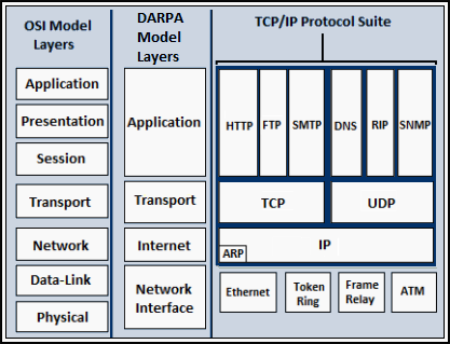
At the beginning of the week, I decided to inform myself a little more about the internet protocols, understanding that in these cases it would be necessary to follow this schematic to interconnect devices over the internet.
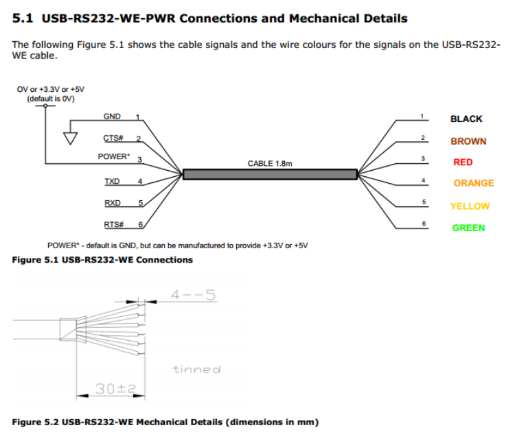
 Finally, although I started reading the part of the DNS application protocol I decided to use a serial bus connection to connect different boards, trying to put my final project PCBs to be able to interconnect them. In my case it would be through an RS-232 cable and adapting the boards to these types of cables that use the RXD and TXD pins.
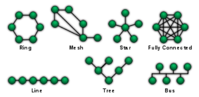
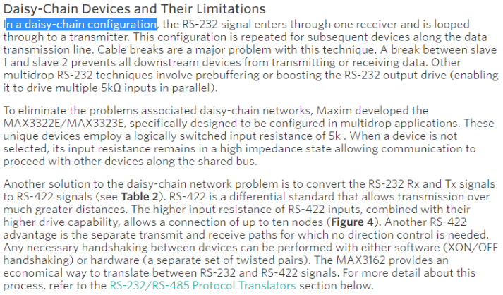
 Once I recognized the protocol or the connections that I must use to interconnect my boards, I had to know what the connection topology was going to be. Finally I decided on the most common linear (Daisy chain), because the components I had didn't need another type of connection more complex or simpler as the point to point.
 The main information that should be used would be about the RS 232 / RS 422 / RS 485. Once these elements are defined, it is not possible to see how the Rs 232 connection can be made daisy chain. As well as problems that could arise to be forewarned.
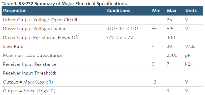
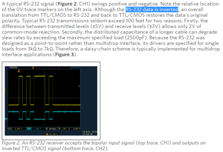
The first thing that are shown are the parameters that must be taken into account in the RS232 protocol.
 After these it was important to note that RS232 transfers the data in inverted form.
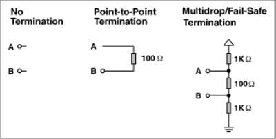
 When applying RS232 in a multi-point structure some modifications have to be made as shown in the following images.
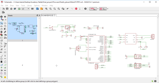
 DESIGN OF PCB:
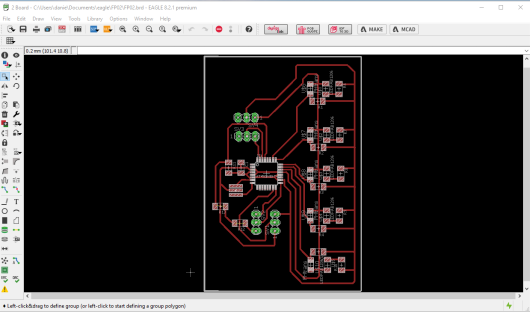
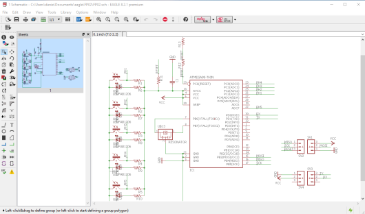
I started by adapting the boards I had designed to create a network. First add the ISP head and GND, VCC, RX and TX to my output board.
DESIGN OF PCB:
I started by adapting the boards I had designed to create a network. First add the ISP head and GND, VCC, RX and TX to my output board.
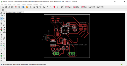
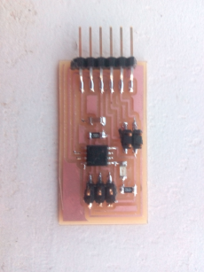
 After adapting the node of the motors, design the sensor board that will need to recognize the line, for it will have to take 5 phototransistors with 5 leds, as it will also be a node, it will have an ISP head and the connections TX and RX.
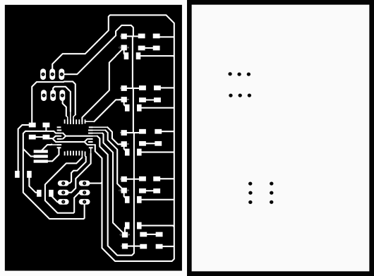
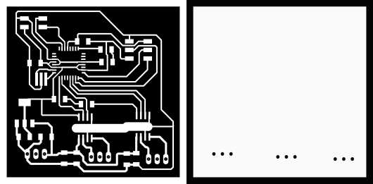
 Finally I decided to modify it so that I could use it in the final project. And they were like this.
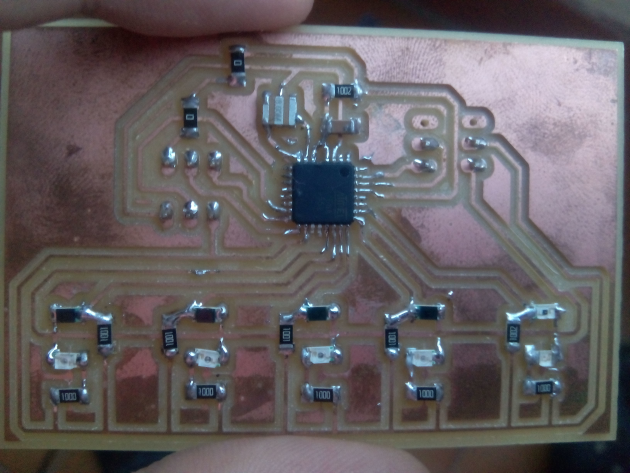
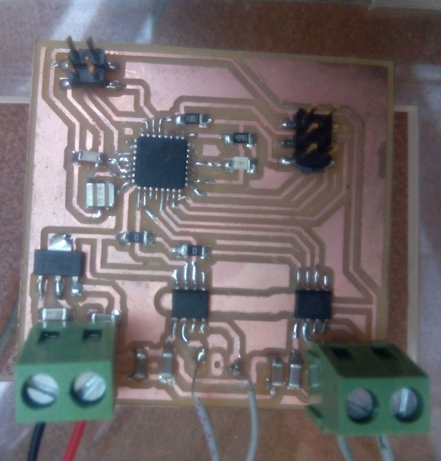 I had enough problems to connect these boards, especially since it does not include an FTDI so that to program them you have a problem with the connection of the cables. Finally I realized that to program the board I needed the Tx and Rx cables to be crossed while to receive the information they did not have to be crossed. When using the output pins larger than the standard heads use female-female cables that also complicated this connection process.
Perform a first series programming on these two plates for use in my dino-robot.
This was his programming:
THE SENSOR PROGRAMMING
int sensorMid = A1 ;
int sensorRight = A2;
int sensorRight2 = A3;
int sensorLeft = A0;
int sensorLeft2 = 7;

int lectura1 = 0;
int total1 = 0;
int media1 = 0;
int lectura2 = 0;
int total2 = 0;
int media2 = 0;
void setup() {
   Serial.begin(9600);

}

void loop() {

  for(int i=0; i< 30;i++){
    lectura1 = analogRead(sensorRight);
    total1 = total1 + lectura1;
   }
  media1  = total1 / 30;
  if(media1 <=500){
  Serial.println('a');
  delay(10);
  }

  total1 = 0;

    for(int i=0; i< 30;i++){
    lectura2 = analogRead(sensorLeft);
    total2 = total2 + lectura2;
   }
  media2  = total2 / 30;
  if(media2 <=500){
  Serial.println('b');
  delay(10);
  }

  total2 = 0;
}
MOTOR PROGRAMMING
 int in1Motor1= 5;
int in2Motor1= 6;
int in1Motor2= 9;
int in2Motor2= 10;
int encendido =0;
void setup() {
  // put your setup code here, to run once:
pinMode(in1Motor1,OUTPUT);
pinMode(in2Motor1,OUTPUT);
pinMode(in1Motor2,OUTPUT);
pinMode(in2Motor2,OUTPUT);
Serial.begin(9600);

}

void loop() {
  // put your main code here, to run repeatedly:

  analogWrite(in1Motor1,22);
  analogWrite(in2Motor1,0);
  analogWrite(in1Motor2,20);
  analogWrite(in2Motor2,0);
  if(Serial.available()){
    encendido= Serial.read();

    if(encendido== 'a'){
  analogWrite(in1Motor1,62);
  analogWrite(in2Motor1,0);
  digitalWrite(in1Motor2,HIGH);
  digitalWrite(in2Motor2,HIGH);
 //Serial.println('a');
  delay(3);
    }

    else if(encendido== 'b'){
  digitalWrite(in1Motor1,HIGH);
  digitalWrite(in2Motor1,HIGH);
  analogWrite(in1Motor2,60);
  analogWrite(in2Motor2,0);
 //Serial.println('b');
  delay(3);
}
 }
To see how it works you can see the video HERE.
Finally, make one more plate to interact with it.

 For the programming of a master-slave bus serial connection, what was to be done was to define each board with a specific address. And the master is the computer.
SLAVE 1 PROGRAMMING
int in1Motor1= 5;
int in2Motor1= 6;
int encendido =0;

int name = 2; // id 2
int Tx = 1; // pin Tx

void setup() {
  // put your setup code here, to run once:
pinMode(in1Motor1,OUTPUT);
pinMode(in2Motor1,OUTPUT);

Serial.begin(9600);

}

void loop() {
  // Tx in tristate
   digitalWrite( Tx, LOW );
pinMode( Tx, OUTPUT );
pinMode( Tx, INPUT );


 if(Serial.available()){
    encendido= Serial.read();
        if(encendido == name){
pinMode( Tx, OUTPUT );
  analogWrite(in1Motor1,62);
  analogWrite(in2Motor1,0);
  delay(1000);
  Serial.print ("node 2");
    }

}
 }
SLAVE 2 PROGRAMMING
int ledPin = 0;
int encendido = 0;

int name = 3;
int Tx = 1;

void setup() {
Serial.begin(9600);
  pinMode(ledPin,OUTPUT);
}

void loop() {

  // Tx in tristate
   digitalWrite( Tx, LOW );
pinMode( Tx, OUTPUT );
pinMode( Tx, INPUT );

 if(Serial.available()){
    encendido= Serial.read();
        if(encendido == name){
pinMode( Tx, OUTPUT );
digitalWrite(13,HIGH);
delay(1000);
digitalWrite(13,LOW);
delay(1000);
Serial.print ("node 3");
}
}
}
FILES:- Traces Master
- Interior Master
- Traces slave01
- Interior slave01
- Traces slave02
- Interior slave02
- programming master
- programming slave1
- programming slave1 second time
- programming slave2
You can see more files about it HERE.