This week I continued to build and design around my final project. I explored some ways in which I can communicate from a webpage to my solenoid board through an application. I spiraled between communication and applications in order to test capabilities of my final project. In a way this example addresses both Week 16 and Week 17. I continued to develop in the Arduino IDE environment. First, I wrote a program called "HELLO-SOLENOID-ESP" which allows my solenoid board to listen to the sensor board and throw a solenoid valve on and off. I next wrote a program called "esp8266-webserver-graphical-lumionox-o2-solenoid-test" which runs as a webserver, which generates a webpage which allows the client to press one of two buttons.
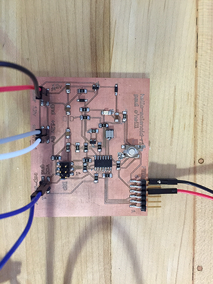
I adapted this program from one of the example sketches included with the Arduino IDE for my hello-solenopid-r13 board. I added the solenoid to act in parallel to the LED. This board is based on the ATMEL ATTiny44 which is 5 volt based. The solenoid valve is 12 volts. In previos boards, I cooked the voltage regulator because the board was being powered from two sources, which "goofed" up the voltage regulator and caused it to fail. I added diodes to protect the voltage regulator. Nevertheless, I use a programmer which has the ability to power or not power the board. I had good success with the "Sparkfun AVR pocket programmer" available through Digikey, part number 1568-1080-ND for $14.95. I highly recommend it. It is convenient to leave power off and keep debuigging your board without having to worry about frying a voltage regulator.
---------------------------------------------------------------------------------------------------------------
#include <SoftwareSerial.h>
/*
Blink
Turns on an LED on for one second, then off for one second, repeatedly.
Most Arduinos have an on-board LED you can control. On the UNO, MEGA and ZERO
it is attached to digital pin 13, on MKR1000 on pin 6. LED_BUILTIN is set to
the correct LED pin independent of which board is used.
If you want to know what pin the on-board LED is connected to on your Arduino model, check
the Technical Specs of your board at https://www.arduino.cc/en/Main/Products
This example code is in the public domain.
modified 8 May 2014
by Scott Fitzgerald
modified 2 Sep 2016
by Arturo Guadalupi
modified 8 Sep 2016
by Colby Newman
*/
const int LED = 7; //TINY44 PA7
const int SOLENOID = 8; //TINY44 PB2, IDE 8, pin 5
const int ESP = 2; //TINY44 PA2, IDE 2, pin 11
const int BUTTON = 10; //TINY44 button connected to PA3, IDE 3, pin 10
// the setup function runs once when you press reset or power the board
void setup() {
// initialize digital pin LED_BUILTIN as an output.
pinMode(LED, OUTPUT);
pinMode(SOLENOID, OUTPUT);
pinMode(ESP, INPUT);
pinMode(BUTTON, INPUT);
// Serial.begin(9600);
}
// the loop function runs over and over again forever
void loop() {
int ESPValue=digitalRead(ESP);
// Serial.println(ESPValue);
if (ESPValue > 0) {
delay(1);
digitalWrite(LED, HIGH);
//digitalWrite(INPUTLINE, HIGH);
digitalWrite(SOLENOID, HIGH);
} else {
digitalWrite(LED, LOW); // turn the LED off by making the voltage LOW
digitalWrite(SOLENOID, LOW);
/*
digitalWrite(LED, HIGH); // turn the LED on (HIGH is the voltage level)
// digitalWrite(INPUTLINE, HIGH);
digitalWrite(SOLENOID, HIGH);
delay(2500); // wait for a second
digitalWrite(LED, LOW); // turn the LED off by making the voltage LOW
// digitalWrite(INPUTLINE, LOW);
digitalWrite(SOLENOID, LOW);
delay(1000); // wait for a second
*/
}
}
---------------------------------------------------------------------------------------------------------------
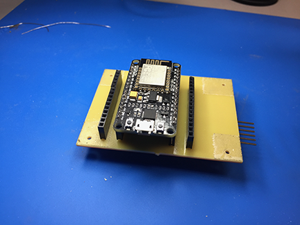
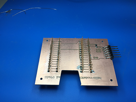
I wrote this program to demonstrate an application program that runs on the internet and controls the hello-nodeMCU board, which yet controls the solenoid board. The hardest part here is mapping out physical pins to GPIO pins on the ESP8266. This is why I made a shield with a couple of extra headers, so I could move jumper wires around until I found the GPIO that works.
---------------------------------------------------------------------------------------------------------------
/*
ESP8266 Server program to read Luminox O2 sensor.
By: Paul O'Neill
(C) Copyright Paul X. O'Neill, All rights reserved.
Receives from software serial port, sends to hardware serial port.
* RX is digital pin 10 (connect to TX of level shifter: pin B1)
* TX is digital pin 11 (connect to RX of level shifter: pin B2)
The code was written for hello-nodeMCU and Arduino IDE ver. 1.6.1.
*/
#include <ESP8266WiFi.h>
#include <ESP8266WebServer.h>
const char* ssid = "backbarn";
const char* password = "fabacademy";
String form = "<form action='led'><input type='radio' name='state' value='0' checked>On<input type='radio' name='state' value='1'>Off<input type='submit' value='Submit'></form>";
String imagepage = "<img src='/led.png'>";
// This is a png file (led.png)
const char image[] = {
0x89, 0x50, 0x4e, 0x47, 0x0d, 0x0a, 0x1a, 0x0a, 0x00, 0x00, 0x00, 0x0d, 0x49, 0x48, 0x44, 0x52,
0x00, 0x00, 0x00, 0x10, 0x00, 0x00, 0x00, 0x10, 0x08, 0x02, 0x00, 0x00, 0x00, 0x90, 0x91, 0x68,
0x36, 0x00, 0x00, 0x00, 0x01, 0x73, 0x52, 0x47, 0x42, 0x00, 0xae, 0xce, 0x1c, 0xe9, 0x00, 0x00,
0x00, 0x04, 0x67, 0x41, 0x4d, 0x41, 0x00, 0x00, 0xb1, 0x8f, 0x0b, 0xfc, 0x61, 0x05, 0x00, 0x00,
0x00, 0x20, 0x63, 0x48, 0x52, 0x4d, 0x00, 0x00, 0x7a, 0x26, 0x00, 0x00, 0x80, 0x84, 0x00, 0x00,
0xfa, 0x00, 0x00, 0x00, 0x80, 0xe8, 0x00, 0x00, 0x75, 0x30, 0x00, 0x00, 0xea, 0x60, 0x00, 0x00,
0x3a, 0x98, 0x00, 0x00, 0x17, 0x70, 0x9c, 0xba, 0x51, 0x3c, 0x00, 0x00, 0x00, 0x18, 0x74, 0x45,
0x58, 0x74, 0x53, 0x6f, 0x66, 0x74, 0x77, 0x61, 0x72, 0x65, 0x00, 0x50, 0x61, 0x69, 0x6e, 0x74,
0x2e, 0x4e, 0x45, 0x54, 0x20, 0x76, 0x33, 0x2e, 0x33, 0x36, 0xa9, 0xe7, 0xe2, 0x25, 0x00, 0x00,
0x00, 0x57, 0x49, 0x44, 0x41, 0x54, 0x38, 0x4f, 0x95, 0x52, 0x5b, 0x0a, 0x00, 0x30, 0x08, 0x6a,
0xf7, 0x3f, 0xf4, 0x1e, 0x14, 0x4d, 0x6a, 0x30, 0x8d, 0x7d, 0x0d, 0x45, 0x2d, 0x87, 0xd9, 0x34,
0x71, 0x36, 0x41, 0x7a, 0x81, 0x76, 0x95, 0xc2, 0xec, 0x3f, 0xc7, 0x8e, 0x83, 0x72, 0x90, 0x43,
0x11, 0x10, 0xc4, 0x12, 0x50, 0xb6, 0xc7, 0xab, 0x96, 0xd0, 0xdb, 0x5b, 0x41, 0x5c, 0x6a, 0x0b,
0xfd, 0x57, 0x28, 0x5b, 0xc2, 0xfd, 0xb2, 0xa1, 0x33, 0x28, 0x45, 0xd0, 0xee, 0x20, 0x5c, 0x9a,
0xaf, 0x93, 0xd6, 0xbc, 0xdb, 0x25, 0x56, 0x61, 0x01, 0x17, 0x12, 0xae, 0x53, 0x3e, 0x66, 0x32,
0xba, 0x00, 0x00, 0x00, 0x00, 0x49, 0x45, 0x4e, 0x44, 0xae, 0x42, 0x60, 0x82
};
// HTTP server will listen at port 80
ESP8266WebServer server(80);
const int solenoid = 16; //ESP-12 pin1, D0, GPIO 16
const int led = 4; //ESP-12 pin3, D2, GPIO 4
void handle_adc() {
float val = analogRead(0);
server.send(200, "text/plain", String(val));
}
void handle_led() {
// get the value of request argument "state" and convert it to an int
int state = server.arg("state").toInt();
digitalWrite(led, state);
digitalWrite(solenoid, state);
server.send(200, "text/plain", String("LED is now ") + ((state)?"off":"on"));
}
void handle_image() {
server.send(200, "image/png", "");
WiFiClient client = server.client();
client.write(image, sizeof(image));
}
void handle_webpage_with_image() {
server.send(200, "text/html", imagepage);
}
void setup(void) {
Serial.begin(9600);
Serial.println("");
pinMode(led, OUTPUT);
pinMode(solenoid, OUTPUT);
// Connect to WiFi network
WiFi.begin(ssid, password);
// Wait for connection
while (WiFi.status() != WL_CONNECTED) {
delay(500);
Serial.print("-SOLENOID TEST-");
digitalWrite(solenoid, HIGH); // turn the SOLENOID on (HIGH is the voltage level)
delay(1000); // wait for a second
digitalWrite(solenoid, LOW); // turn the SOLENOID off by making the voltage LOW
delay(1000); // wait for a second
digitalWrite(solenoid, HIGH); // turn the SOLENOID on (HIGH is the voltage level)
delay(1000); // wait for a second
digitalWrite(solenoid, LOW); // turn the SOLENOID off by making the voltage LOW
delay(1000); // wait for a second
digitalWrite(solenoid, HIGH); // turn the SOLENOID on (HIGH is the voltage level)
delay(1000); // wait for a second
digitalWrite(solenoid, LOW); // turn the SOLENOID off by making the voltage LOW
delay(1000); // wait for a second
}
Serial.println("");
Serial.print("Connected to ");
Serial.println(ssid);
Serial.print("IP address: ");
Serial.println(WiFi.localIP());
// Set up the endpoints for HTTP server
//
// Endpoints can be written as inline functions:
server.on("/", [](){
server.send(200, "text/html", form);
});
// And as regular external functions:
server.on("/adc", handle_adc);
server.on("/led", handle_led);
server.on("/led.png", handle_image);
server.on("/showled", handle_webpage_with_image);
// Start the server
server.begin();
Serial.println("HTTP server started");
}
void loop(void) {
// check for incomming client connections frequently in the main loop:
server.handleClient();
}
---------------------------------------------------------------------------------------------------------------
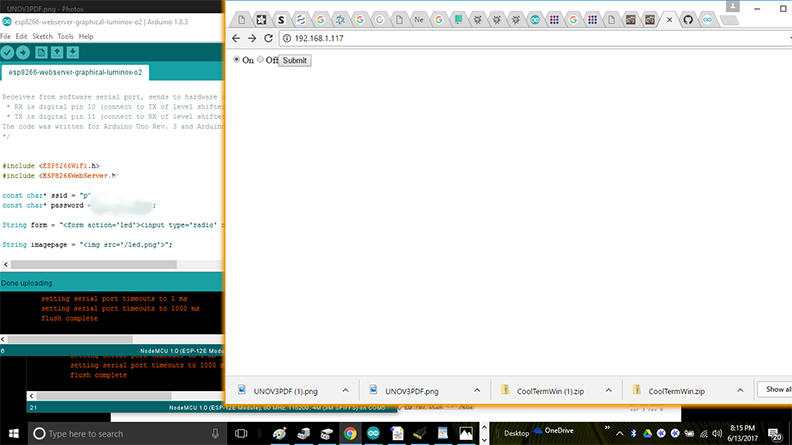
Screenshot of client page. The server is located at local IP address 192.168.1.117 and the solenoid is ion the ON state.