This week I will explore a couple of devices discussed by Neil. One is a WIFI (802.11) device and one is a Bluetooth device. I did not see any of these devices, or "modules" in the LCCC FabLab inventory, so I ordered some.
WIFI Device: ESP8266
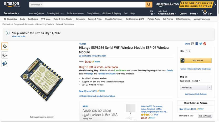
Neil stated that these devices are assembled cards with an integrated antenna. They are readily available on Amazon, and though there is some sort of specification for this device, there are variations between manufacturers including different features and build qualities.
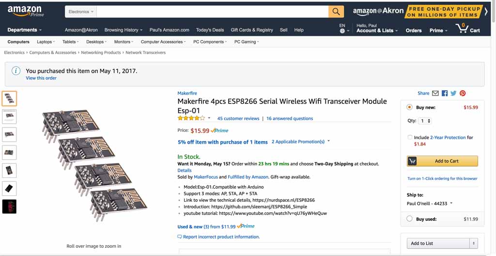
This ESP8266 WIFI module appears to have an antenna jack in the lower left corner, and can be soldered to a pc board of my design. I found an EAGLE library for ESP8266 which has ESP-07 listed.
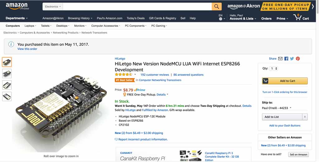
This module comes complete with header pins and a micro-USB. There is a USB to serial chip on the module.
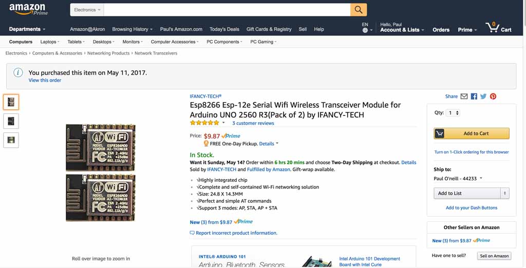
This is a ESP8266 WIFI module has the antenna integral to the module and is designed to be board mounted and having a ESP-12E layout.
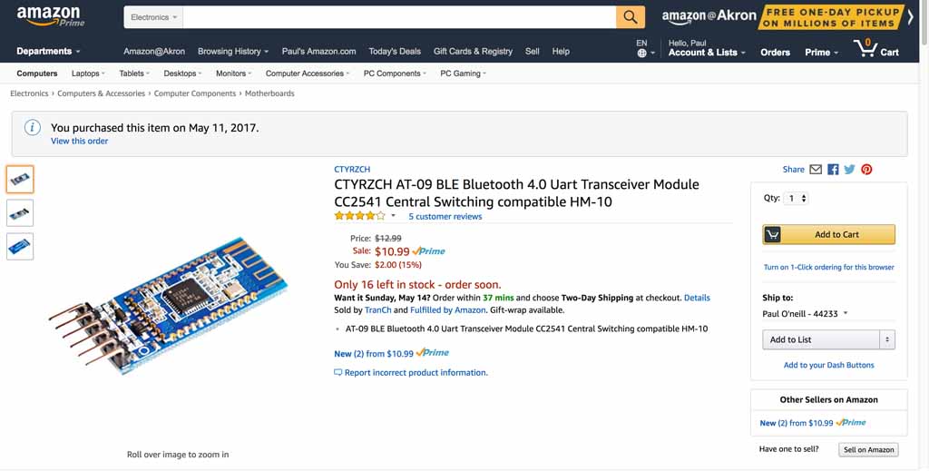
This is a CC2541 Bluetooth module. It states it is "Central Switching compatable HM-10" and AT-09 BLE.

I ordered pairs of everything. Never seen these before, so I tought I would touch and feel at first. I focused on the ESP8266-12E for my "all-in-one" board concept, and the nodeMCU module for the multi-board concept. I also orderded pairs of the BLE modules in case I couldn't figure out the ESP. The sense I got from Neil's lectures and in reviewing prior Fabacademy work with the ESP, that they are difficult. Furthermore, the O2 sensor I was seriously considering was actually a sensor with a built-in processor, communicating via RS232. This was starting to get complicated. When things get complicated, divide and conquor. Break big problems into smaller problems. Small chunks are easier to digest than big ones.
I have to read the data sheets and evaluate what is required to operate these modules. They seem to be orientated to Arduino. The Fabacademy Commercial Board policy seems to allow using commercial boards on shields which are fabbed to demonstrate the shields can network. It is not clear if one Fabduino needs to be built for this weeks project, so I should reach out to my instructor. I am also interested in using serial communication to talk with serial based sensors, which may be used in my final project. I need some clarification from my remote guru if that applies to the weekly assignment. Are the ESP modules commercial boards? Are they soon to be part of the Fablab inventory? I really thought a sensor shield using the nodeMCU made sense for this project.
I spent time with my instructor reviewing my output board in which I fried the voltage regulator. Chris Rohal suspected that my programmer backfed power to the voltage regulator which caused it to malfunction and burn. This can be correctecd by protecting the VR with a diode. I also explained to Chris that the ESP8266 requires 3.3 volts wherein the Tiny44 runs on 5 volts. My "hello output" bopard was getting a little crowded with everyrthing being on one side, so I will try to solve the problem by communicating from the Tiny44 to the ESP8266 via an available pin. I will also build the ESP8266-12e on a seperate board with it's own headers which will allow the O2 sensor to be connected through serial RX and TX at 3.3V which is the same as the ESP.
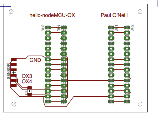
I further discussed with my instructor, Chris Rohal, my final project and how I planned on chaining more than one board together, and also the all-in-one board concept. Chris seemed to think I had a good concept, so I proceeded on fabrication. The concept is to utilize the hello-output design from earlier so it can control and power a solenoid valve. I would also need to open up an input port on the ATTiny44 which would allow my "Wifi/sensor board" to communicate with. I decided to name the two boards "hello-solenoid" and "hello-nodeMCU". I ended up designing and making many versions of these boards. I program and tested the boards first with simple LED blink programs, and then I continued on to making connections between the two boards via a breadboard and a regulated power supply.
Files:
Data sheet WIFI Module ESP8266:


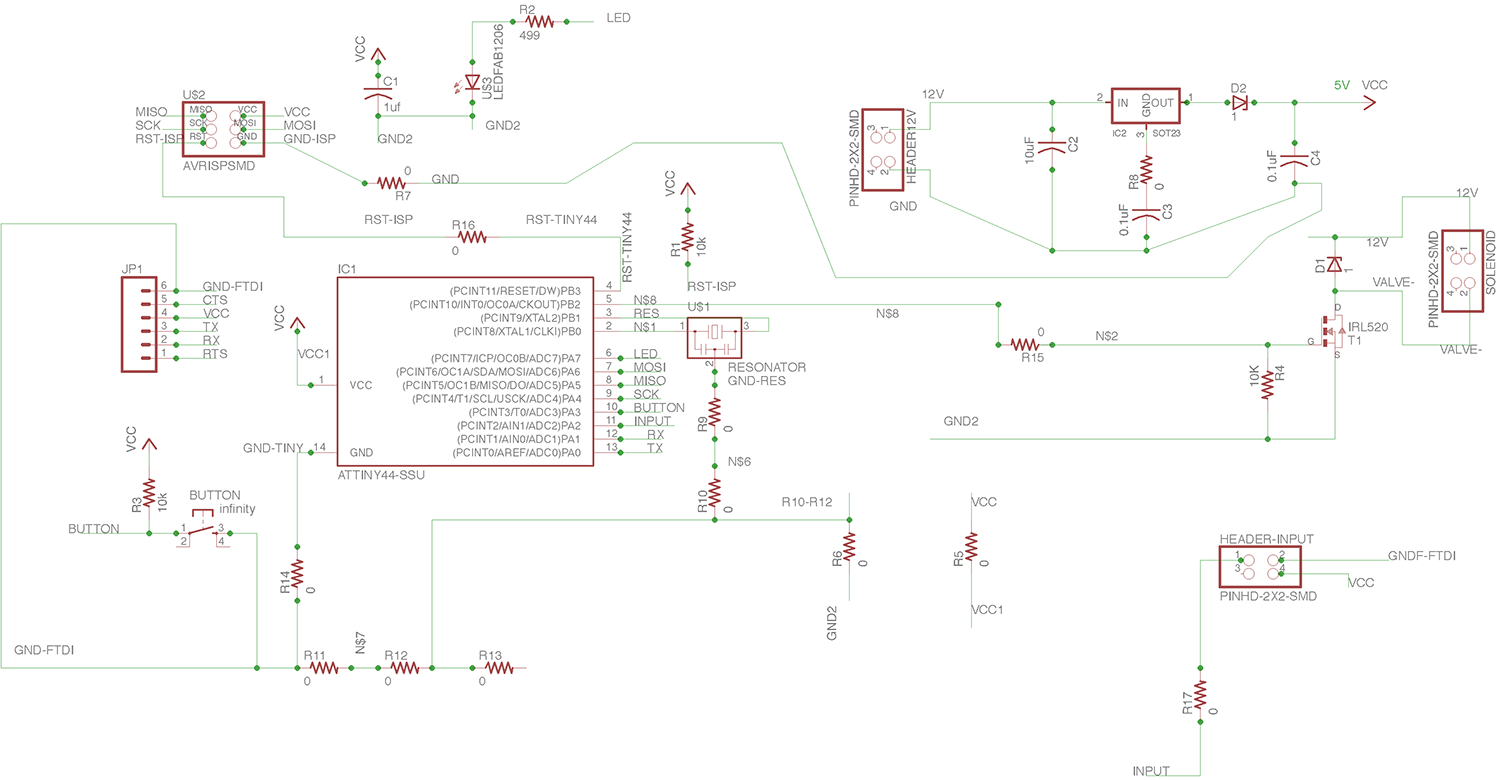
The Hello-Solenoid board is a descendant from the project we did on Week 8. This is a better version which addresses some of the failures of the earlier project. Designed using Eagle version 7.70 (Mac).
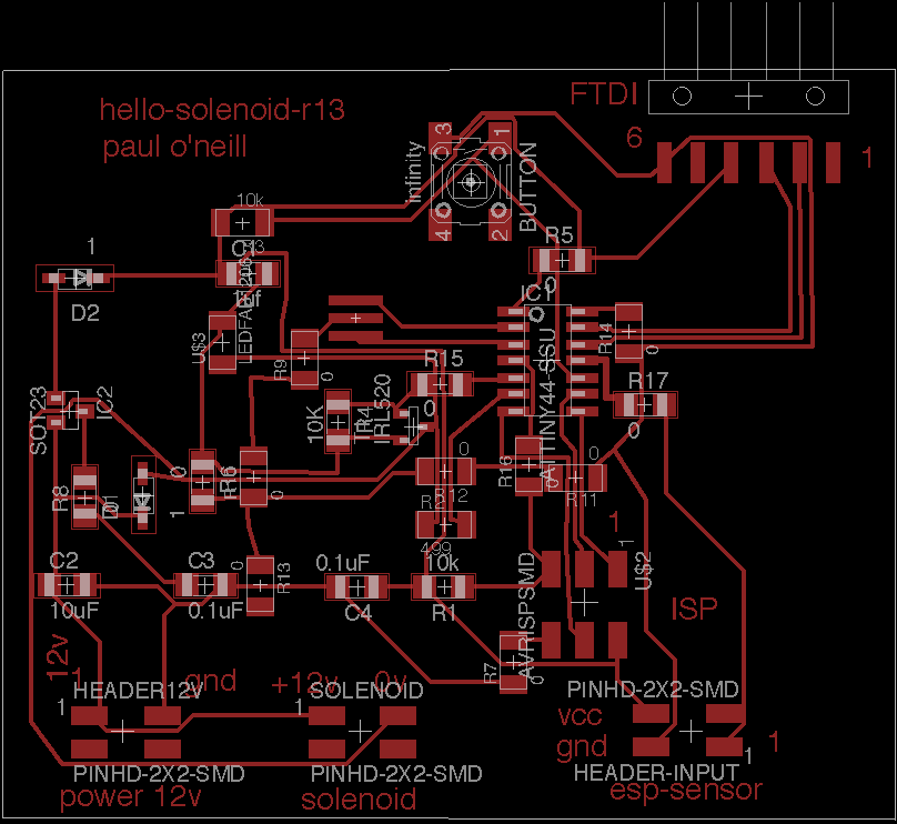
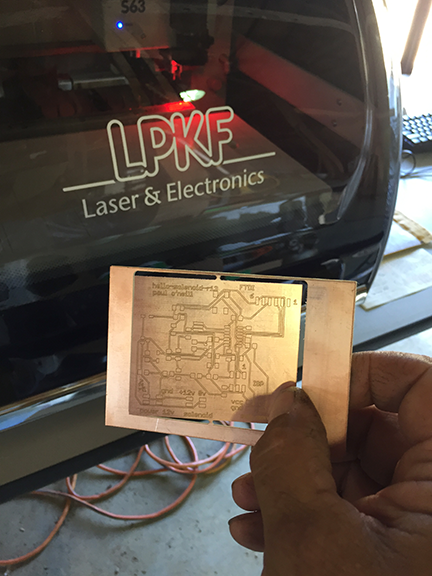
Convert Eagle file to Gerber file and cut on my LPKF board mill.
I adapted this program from one of the example sketches included with the Arduino IDE for my hello-solenopid-r13 board. I added the solenoid to act in parallel to the LED. This board is based on the ATMEL ATTiny44 which is 5 volt based. The solenoid valve is 12 volts. In previos boards, I cooked the voltage regulator because the board was being powered from two sources, which "goofed" up the voltage regulator and caused it to fail. I added diodes to protect the voltage regulator. Nevertheless, I use a programmer which has the ability to power or not power the board. I had good success with the "Sparkfun AVR pocket programmer" available through Digikey, part number 1568-1080-ND for $14.95. I highly recommend it. It is convenient to leave power off and keep debuigging your board without having to worry about frying a voltage regulator.
---------------------------------------------------------------------------------------------------------------
#include <SoftwareSerial.h>
/*
Blink
Turns on an LED on for one second, then off for one second, repeatedly.
Most Arduinos have an on-board LED you can control. On the UNO, MEGA and ZERO
it is attached to digital pin 13, on MKR1000 on pin 6. LED_BUILTIN is set to
the correct LED pin independent of which board is used.
If you want to know what pin the on-board LED is connected to on your Arduino model, check
the Technical Specs of your board at https://www.arduino.cc/en/Main/Products
This example code is in the public domain.
modified 8 May 2014
by Scott Fitzgerald
modified 2 Sep 2016
by Arturo Guadalupi
modified 8 Sep 2016
by Colby Newman
*/
const int LED = 7; //TINY44 PA7
const int SOLENOID = 8; //TINY44 PB2, IDE 8, pin 5
const int ESP = 2; //TINY44 PA2, IDE 2, pin 11
const int BUTTON = 10; //TINY44 button connected to PA3, IDE 3, pin 10
// the setup function runs once when you press reset or power the board
void setup() {
// initialize digital pin LED_BUILTIN as an output.
pinMode(LED, OUTPUT);
pinMode(SOLENOID, OUTPUT);
pinMode(ESP, INPUT);
pinMode(BUTTON, INPUT);
// Serial.begin(9600);
}
// the loop function runs over and over again forever
void loop() {
int ESPValue=digitalRead(ESP);
// Serial.println(ESPValue);
if (ESPValue > 0) {
delay(1);
digitalWrite(LED, HIGH);
//digitalWrite(INPUTLINE, HIGH);
digitalWrite(SOLENOID, HIGH);
} else {
digitalWrite(LED, LOW); // turn the LED off by making the voltage LOW
digitalWrite(SOLENOID, LOW);
/*
digitalWrite(LED, HIGH); // turn the LED on (HIGH is the voltage level)
// digitalWrite(INPUTLINE, HIGH);
digitalWrite(SOLENOID, HIGH);
delay(2500); // wait for a second
digitalWrite(LED, LOW); // turn the LED off by making the voltage LOW
// digitalWrite(INPUTLINE, LOW);
digitalWrite(SOLENOID, LOW);
delay(1000); // wait for a second
*/
}
}
---------------------------------------------------------------------------------------------------------------
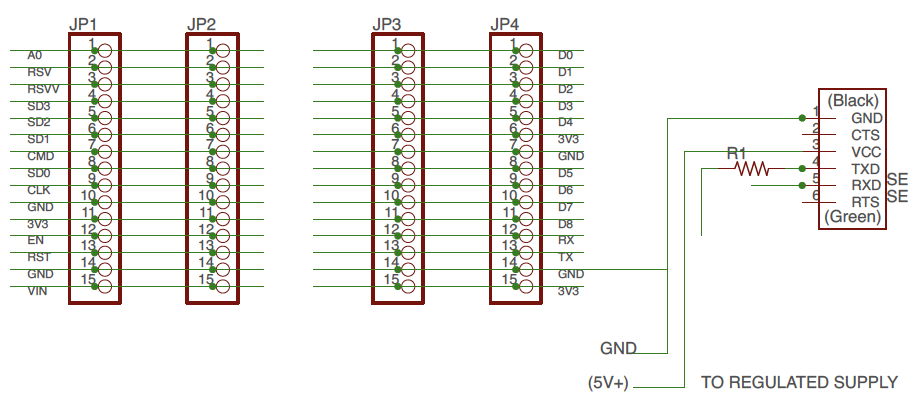
Note: Resistor R1 is a zero-ohm jumper.
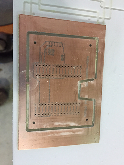
Board engraved and drilled on LPKF mill.
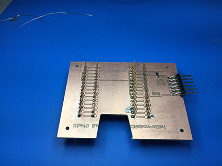
Header pins inserted into drilled holes and soldered. You need 0.80 mm
drill bit to get close tolerance hole for solder to bridge between pin and board.
These type of header pins not found in FabLab inventory. You can find them
in the Adafruit git repository for Eagle CAD.
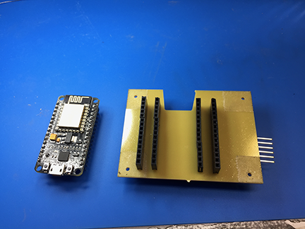
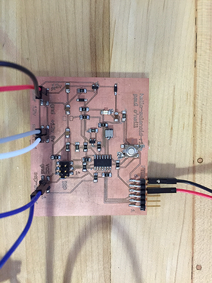
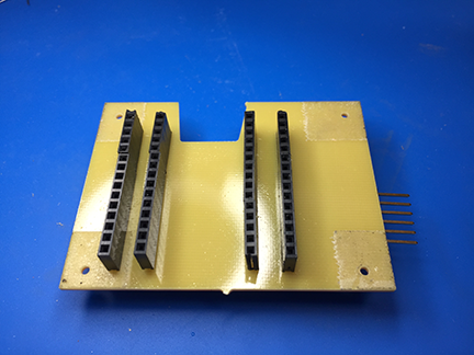
The nodeMCU before insertion intop the shield.
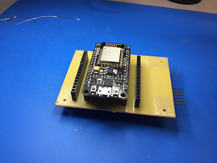
The ESP8266-12 nodeMCU installed into the shield. These can be bought for around $10.
I wrote this program to demonstrate an application program that runs on the internet and controls the hello-nodeMCU board, which yet controls the solenoid board. The hardest part here is mapping out physical pins to GPIO pins on the ESP8266. This is why I made a shield with a couple of extra headers, so I could move jumper wires around until I found the GPIO that works.
---------------------------------------------------------------------------------------------------------------
/*
ESP8266 Server program to read Luminox O2 sensor.
By: Paul O'Neill
(C) Copyright Paul X. O'Neill, All rights reserved.
Receives from software serial port, sends to hardware serial port.
* RX is digital pin 10 (connect to TX of level shifter: pin B1)
* TX is digital pin 11 (connect to RX of level shifter: pin B2)
The code was written for hello-nodeMCU and Arduino IDE ver. 1.6.1.
*/
#include <ESP8266WiFi.h>
#include <ESP8266WebServer.h>
const char* ssid = "backbarn";
const char* password = "fabacademy";
String form = "<form action='led'><input type='radio' name='state' value='0' checked>On<input type='radio' name='state' value='1'>Off<input type='submit' value='Submit'></form>";
String imagepage = "<img src='/led.png'>";
// This is a png file (led.png)
const char image[] = {
0x89, 0x50, 0x4e, 0x47, 0x0d, 0x0a, 0x1a, 0x0a, 0x00, 0x00, 0x00, 0x0d, 0x49, 0x48, 0x44, 0x52,
0x00, 0x00, 0x00, 0x10, 0x00, 0x00, 0x00, 0x10, 0x08, 0x02, 0x00, 0x00, 0x00, 0x90, 0x91, 0x68,
0x36, 0x00, 0x00, 0x00, 0x01, 0x73, 0x52, 0x47, 0x42, 0x00, 0xae, 0xce, 0x1c, 0xe9, 0x00, 0x00,
0x00, 0x04, 0x67, 0x41, 0x4d, 0x41, 0x00, 0x00, 0xb1, 0x8f, 0x0b, 0xfc, 0x61, 0x05, 0x00, 0x00,
0x00, 0x20, 0x63, 0x48, 0x52, 0x4d, 0x00, 0x00, 0x7a, 0x26, 0x00, 0x00, 0x80, 0x84, 0x00, 0x00,
0xfa, 0x00, 0x00, 0x00, 0x80, 0xe8, 0x00, 0x00, 0x75, 0x30, 0x00, 0x00, 0xea, 0x60, 0x00, 0x00,
0x3a, 0x98, 0x00, 0x00, 0x17, 0x70, 0x9c, 0xba, 0x51, 0x3c, 0x00, 0x00, 0x00, 0x18, 0x74, 0x45,
0x58, 0x74, 0x53, 0x6f, 0x66, 0x74, 0x77, 0x61, 0x72, 0x65, 0x00, 0x50, 0x61, 0x69, 0x6e, 0x74,
0x2e, 0x4e, 0x45, 0x54, 0x20, 0x76, 0x33, 0x2e, 0x33, 0x36, 0xa9, 0xe7, 0xe2, 0x25, 0x00, 0x00,
0x00, 0x57, 0x49, 0x44, 0x41, 0x54, 0x38, 0x4f, 0x95, 0x52, 0x5b, 0x0a, 0x00, 0x30, 0x08, 0x6a,
0xf7, 0x3f, 0xf4, 0x1e, 0x14, 0x4d, 0x6a, 0x30, 0x8d, 0x7d, 0x0d, 0x45, 0x2d, 0x87, 0xd9, 0x34,
0x71, 0x36, 0x41, 0x7a, 0x81, 0x76, 0x95, 0xc2, 0xec, 0x3f, 0xc7, 0x8e, 0x83, 0x72, 0x90, 0x43,
0x11, 0x10, 0xc4, 0x12, 0x50, 0xb6, 0xc7, 0xab, 0x96, 0xd0, 0xdb, 0x5b, 0x41, 0x5c, 0x6a, 0x0b,
0xfd, 0x57, 0x28, 0x5b, 0xc2, 0xfd, 0xb2, 0xa1, 0x33, 0x28, 0x45, 0xd0, 0xee, 0x20, 0x5c, 0x9a,
0xaf, 0x93, 0xd6, 0xbc, 0xdb, 0x25, 0x56, 0x61, 0x01, 0x17, 0x12, 0xae, 0x53, 0x3e, 0x66, 0x32,
0xba, 0x00, 0x00, 0x00, 0x00, 0x49, 0x45, 0x4e, 0x44, 0xae, 0x42, 0x60, 0x82
};
// HTTP server will listen at port 80
ESP8266WebServer server(80);
const int solenoid = 16; //ESP-12 pin1, D0, GPIO 16
const int led = 4; //ESP-12 pin3, D2, GPIO 4
void handle_adc() {
float val = analogRead(0);
server.send(200, "text/plain", String(val));
}
void handle_led() {
// get the value of request argument "state" and convert it to an int
int state = server.arg("state").toInt();
digitalWrite(led, state);
digitalWrite(solenoid, state);
server.send(200, "text/plain", String("LED is now ") + ((state)?"off":"on"));
}
void handle_image() {
server.send(200, "image/png", "");
WiFiClient client = server.client();
client.write(image, sizeof(image));
}
void handle_webpage_with_image() {
server.send(200, "text/html", imagepage);
}
void setup(void) {
Serial.begin(9600);
Serial.println("");
pinMode(led, OUTPUT);
pinMode(solenoid, OUTPUT);
// Connect to WiFi network
WiFi.begin(ssid, password);
// Wait for connection
while (WiFi.status() != WL_CONNECTED) {
delay(500);
Serial.print("-SOLENOID TEST-");
digitalWrite(solenoid, HIGH); // turn the SOLENOID on (HIGH is the voltage level)
delay(1000); // wait for a second
digitalWrite(solenoid, LOW); // turn the SOLENOID off by making the voltage LOW
delay(1000); // wait for a second
digitalWrite(solenoid, HIGH); // turn the SOLENOID on (HIGH is the voltage level)
delay(1000); // wait for a second
digitalWrite(solenoid, LOW); // turn the SOLENOID off by making the voltage LOW
delay(1000); // wait for a second
digitalWrite(solenoid, HIGH); // turn the SOLENOID on (HIGH is the voltage level)
delay(1000); // wait for a second
digitalWrite(solenoid, LOW); // turn the SOLENOID off by making the voltage LOW
delay(1000); // wait for a second
}
Serial.println("");
Serial.print("Connected to ");
Serial.println(ssid);
Serial.print("IP address: ");
Serial.println(WiFi.localIP());
// Set up the endpoints for HTTP server
//
// Endpoints can be written as inline functions:
server.on("/", [](){
server.send(200, "text/html", form);
});
// And as regular external functions:
server.on("/adc", handle_adc);
server.on("/led", handle_led);
server.on("/led.png", handle_image);
server.on("/showled", handle_webpage_with_image);
// Start the server
server.begin();
Serial.println("HTTP server started");
}
void loop(void) {
// check for incomming client connections frequently in the main loop:
server.handleClient();
}
---------------------------------------------------------------------------------------------------------------
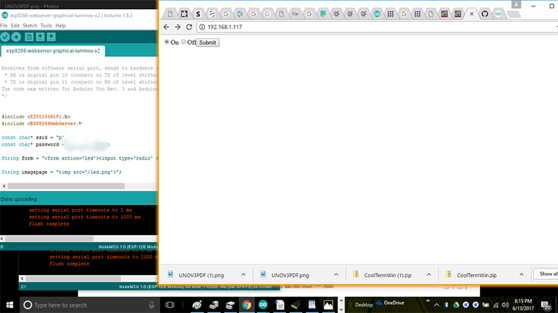
Screenshot of client page. The server is located at local IP address 192.168.1.117 and the solenoid is ion the ON state.

This work is licensed under a Creative Commons Attribution-NonCommercial-NoDerivatives 4.0 International License.