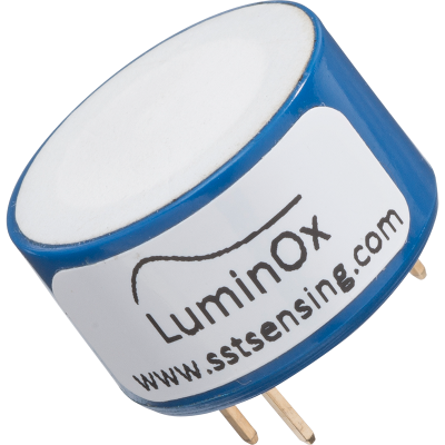
I am planning on using an O2 sensor. The sensor which I like the most is the Luminox LOx2. It is anoptical based sensor, and is purported to last 5 years under normal conditions.
Cost: apx $90. Available from manufacturer, or from Amazon UK.
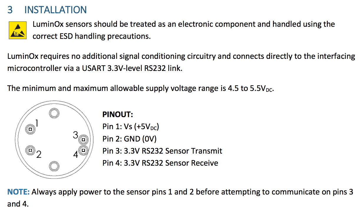
The issue I see swith this sensor is that I will need to supply two different voltages. Pins 1 and 2 basically heat the sensor and illuminate a UV LED and power an embedded processor. Pins 3 and 4 communicate at 3.3V with RS232 serial, 9600 baud rate. In my final project I am planning on using the solenoid board I built earlier for Week 11: "Output Devices". This board is based on an Atmel ATTiny44 and regulates 12 volts DC down to 5 volts. The board was complicated as it was, and I utilized solder pads and flying leads which eventually failed. My next revision will utilize headers for lead connections. I expect utilizing headers will make the card more complicated even still. I don't think I can add more voltage regulators on the card and an additional Tiny44 to perform serial communication implementing UART in software, and not miss data from the sensor, and get all of it to fit into the package size of a double-gang junction box.
Better to divide and conquor. This will make development and testing easier.
I have previewed the ESP series of modules. They are 3.3v based, and have a hardware UART , which seems like a good fit for the Luminox O2 sensor. I figure I will make a sensor shield which combines the ESP and the Luminox. Then the shield will connect to the hello-solenoid board which will have one input available to communicate with the shield.
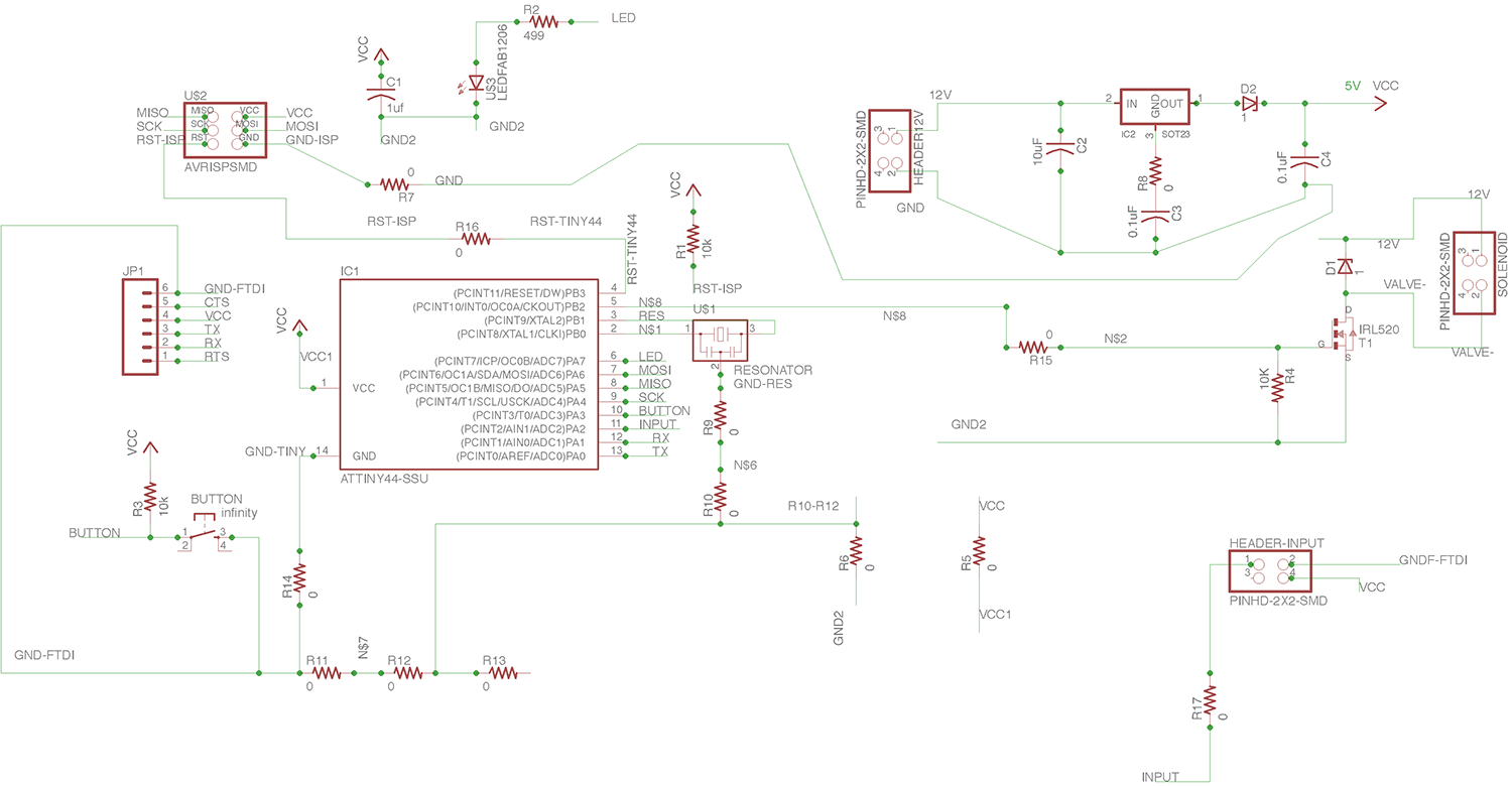
The Hello-Solenoid board is a descendant from the project we did on Week 8. This is a better version which addresses some of the failures of the earlier project. Designed using Eagle version 7.70 (Mac). I am using GPIO 11 as the input port which will connect to the sensor shield.
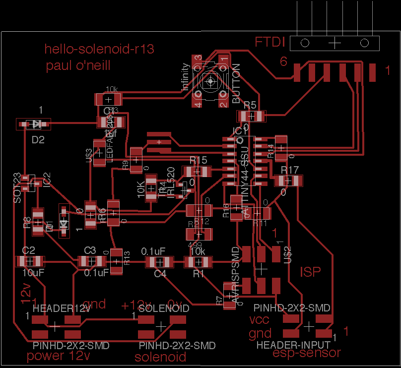
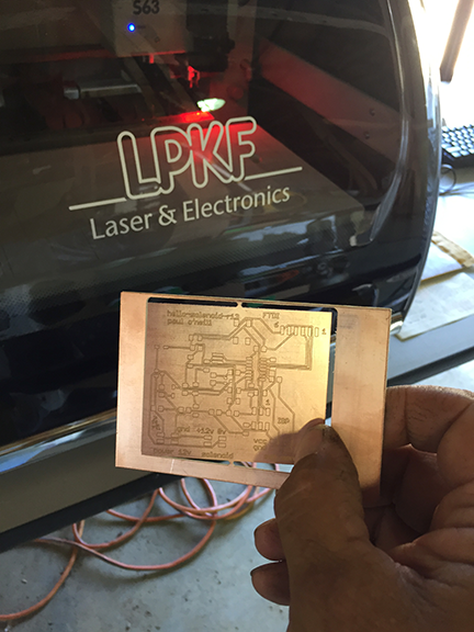
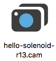
Convert Eagle file to Gerber file and cut on my LPKF board mill.
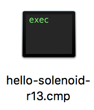
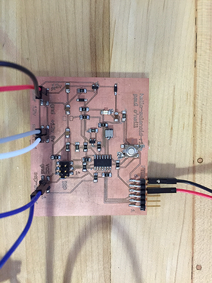
I adapted this program from one of the example sketches included with the Arduino IDE for my hello-solenoid-r13 board. I added the solenoid to act in parallel to the LED. This board is based on the ATMEL ATTiny44 which is 5 volt based. The solenoid valve is 12 volts. In previos boards, I cooked the voltage regulator because the board was being powered from two sources, which "goofed" up the voltage regulator and caused it to fail. I added diodes to protect the voltage regulator. Nevertheless, I use a programmer which has the ability to power or not power the board. I had good success with the "Sparkfun AVR pocket programmer" available through Digikey, part number 1568-1080-ND for $14.95. I highly recommend it. It is convenient to leave power off and keep debuigging your board without having to worry about frying a voltage regulator.
---------------------------------------------------------------------------------------------------------------
#include <SoftwareSerial.h>
/*
Blink
Turns on an LED on for one second, then off for one second, repeatedly.
Most Arduinos have an on-board LED you can control. On the UNO, MEGA and ZERO
it is attached to digital pin 13, on MKR1000 on pin 6. LED_BUILTIN is set to
the correct LED pin independent of which board is used.
If you want to know what pin the on-board LED is connected to on your Arduino model, check
the Technical Specs of your board at https://www.arduino.cc/en/Main/Products
This example code is in the public domain.
modified 8 May 2014
by Scott Fitzgerald
modified 2 Sep 2016
by Arturo Guadalupi
modified 8 Sep 2016
by Colby Newman
*/
const int LED = 7; //TINY44 PA7
const int SOLENOID = 8; //TINY44 PB2, IDE 8, pin 5
const int ESP = 2; //TINY44 PA2, IDE 2, pin 11
const int BUTTON = 10; //TINY44 button connected to PA3, IDE 3, pin 10
// the setup function runs once when you press reset or power the board
void setup() {
// initialize digital pin LED_BUILTIN as an output.
pinMode(LED, OUTPUT);
pinMode(SOLENOID, OUTPUT);
pinMode(ESP, INPUT);
pinMode(BUTTON, INPUT);
// Serial.begin(9600);
}
// the loop function runs over and over again forever
void loop() {
int ESPValue=digitalRead(ESP);
// Serial.println(ESPValue);
if (ESPValue > 0) {
delay(1);
digitalWrite(LED, HIGH);
//digitalWrite(INPUTLINE, HIGH);
digitalWrite(SOLENOID, HIGH);
} else {
digitalWrite(LED, LOW); // turn the LED off by making the voltage LOW
digitalWrite(SOLENOID, LOW);
/*
digitalWrite(LED, HIGH); // turn the LED on (HIGH is the voltage level)
// digitalWrite(INPUTLINE, HIGH);
digitalWrite(SOLENOID, HIGH);
delay(2500); // wait for a second
digitalWrite(LED, LOW); // turn the LED off by making the voltage LOW
// digitalWrite(INPUTLINE, LOW);
digitalWrite(SOLENOID, LOW);
delay(1000); // wait for a second
*/
}
}
---------------------------------------------------------------------------------------------------------------