
I had lots of success 3d printing this week. 3d scanning was not as successful. In addition, when it was time to publish my webpage to the repo with my design files, I overloaded the repository, and my account was locked out for many weeks thereafter. I was not able to complete my page in a timely fashion, and I was not able to update any further pages until the repo was corrected. I had tropuble scanning a simple electrical outlet box. It seemed to make an enourmous amount of data, and still was not creating a decent representation. I brought this to the attention of my instructor, Scott Zitek, and he seemed to be perplexed as to why I was having trouble. Scott offered me to use a milk bottle from the previous year. The equipment still was not scanning the milk bottle accurately. I muddled through the week, disappointed that I didn't get a good result, and that I was blocked from the repo by Fabacademy IT.
I have never 3d printed anything before, so this was a new experience for me. Knowing nothing, I got help from my instructor, Scott Zitek. Scott introduced me to Chris Leon, the resident 3d printing expert at Lorain CCC. Scott provided me a file to tourture test the 3d printer at Lorain County Community College. Later, I learned it is called a massive overhang, and it can be downloaded here: https://www.thingiverse.com/thing:40382
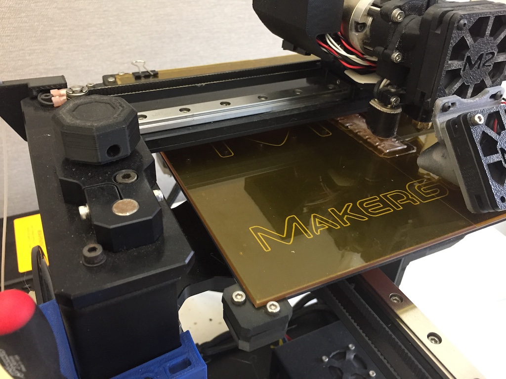
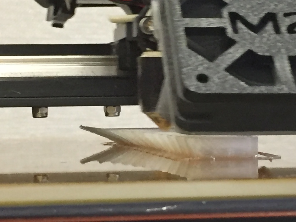
Chris explained the basics of 3d printing to me. He pointed out that at Lorain, they cover the bed of the machine with a release film. This avoids the mess of having to rub the base with glue-sticks. In the above photo, the release film is attached to the glass bed with paper clamps. He also explained the working envelope of the machine is aproximately 8" x 8" x 10".
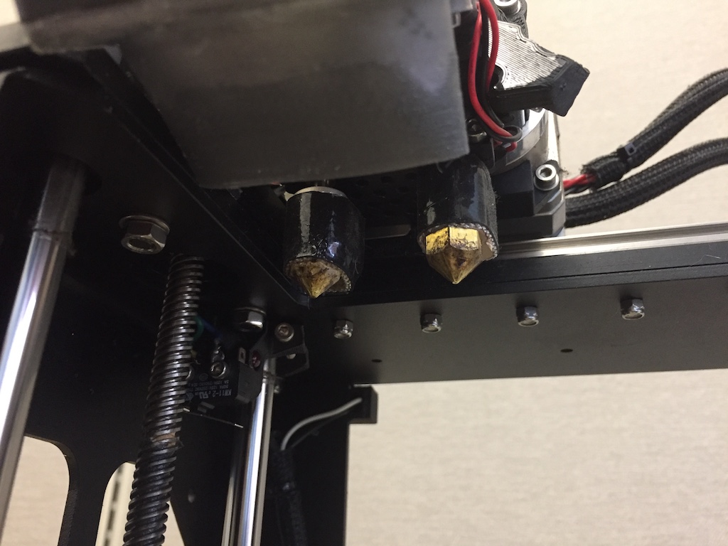
The Makergear M2 at Lorain has dual extruder nozzles, pictured above. Chris explained that the Makergear uses 1.75MM diameter filament. The machine was loaded with PLA filament (PolyLactic Acid). The lab primarily uses PLA, but sometimes also uses ABS (Acrylonitrile Butadiene Styrene). PLA plastic is the easiest plastic to use and is a good material for beginners, and is also economical. PLA is harder than ABS, lays flatter, and easier to print big parts with. It is also more brittle, so in some instances, you may want to make your part with ABS. Also, PLA will "corrode" if left exposed to outdoor elements, so it is best used for items meant for indoor use. Often, the dual head extruders are utilized if you want to print supports with a different type of material. Also, it is sometimes desirable to print a part with two different colors. I never tried different colors, but I did learn that this 3d printer had that capability.
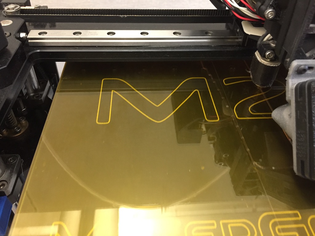
This 3d printer has the ability to heat the bed. You can print directly on the glass bed, or mask it with blue tape, or have a slip sheet. When printing with blue tape, don't heat the bed when using PLA. The slip sheet, pictured above, works well with the bed being heated.
The concept of the test is to see how steep of an overhang you casn print. Usually you have to print "supports" which is material minimally deposited underneath your design to keep it from sagging, and provide a surface on which to build from. 3d printing is like moving a hot melt glue gun around on a CNC gantry. The hot glue stream is very small and can be modified by the size of the tip being used, the temperature which the plastic is being melted, and the type of plastic being used. I performed the test using PLA at 200 degrees F.
There was a dedicated desktop PC along side the 3D printer at LCCC, which was a MakerGear. The software running was Simplify3D. Simplify3D website has some ionformation about adding and modifying supports. It includes a link to a massive overhang test. The webpage where you can download the file can be found here:
https://www.simplify3d.com/support/articles/adding-and-modifying-support-structures/
The files generally used by 3d printers are STL (STereoLithography) files. An STL file is a mesh of triangular planes which approximate your 3d model.
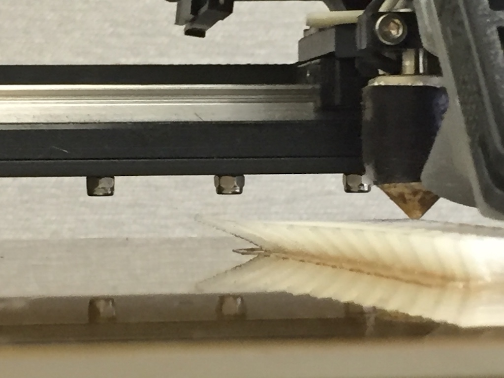
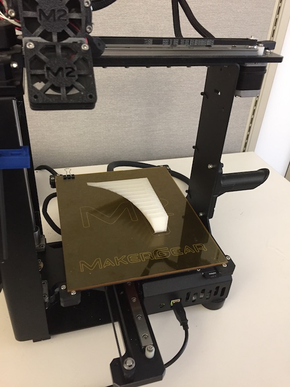
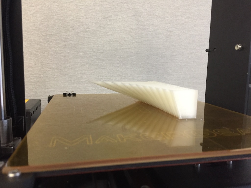
I monitered the "build" of the 3d test piece. No supports, no raft. I was looking for the overhangs to collapse. I kept watching...
To my surprize, the last overhangs did not collapse. Nevertheless, they did not remain flat either. They curved up! The MakerGear M2 seems to be able to perform 55 degree overhangs. Beyond that, things get a little wacky.
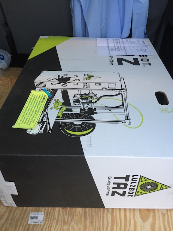
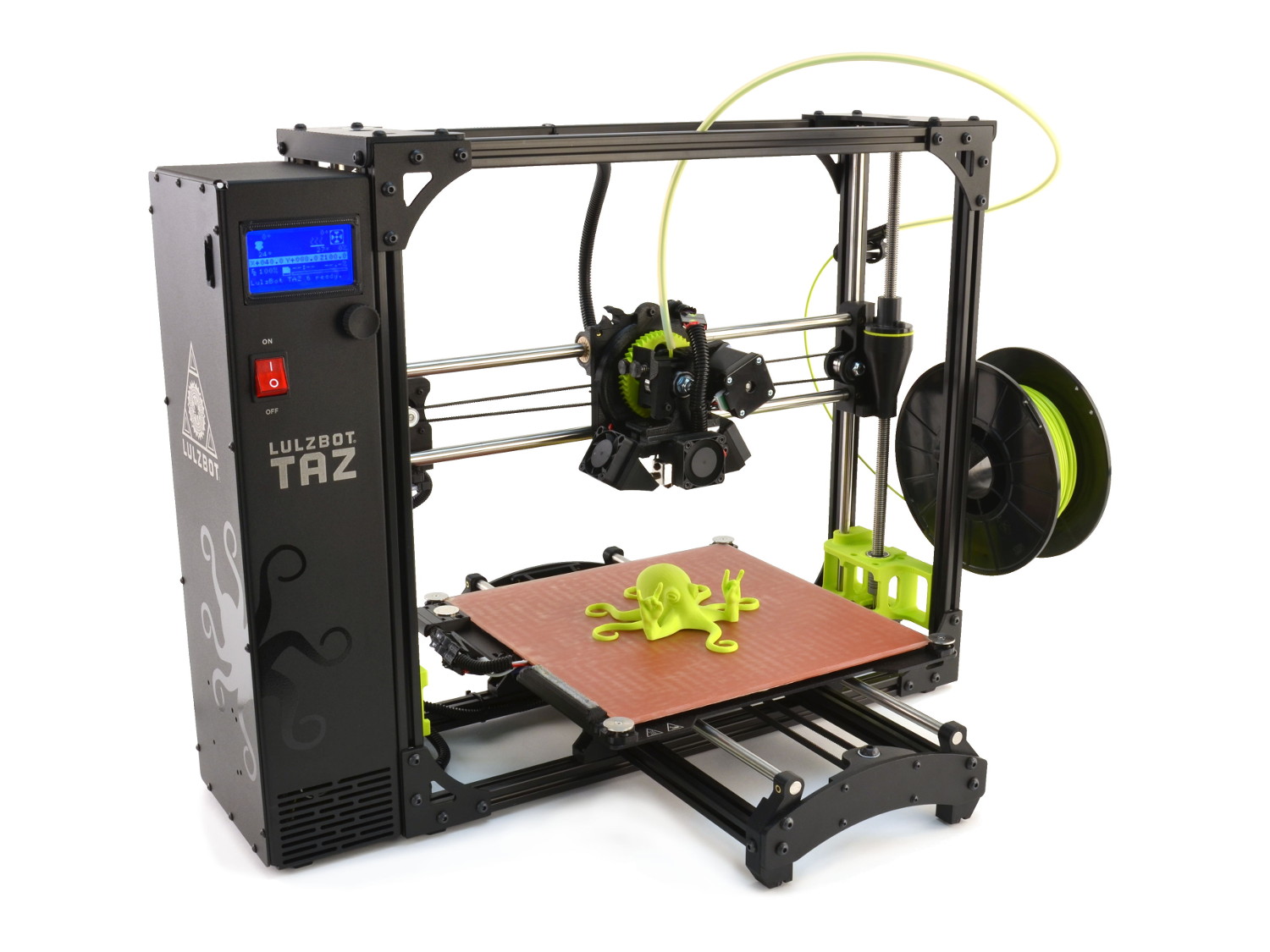
I wanted the convenience of not having to drive an hour each way to LCCC to wait to 3d print, so I went to Microcenter and purchased a Lulzbot Taz 6.
(from TAZ LulzBoy website)
The Lulzbot TAZ 6 has a heated bed, but comes standard with one extruder head for a retail price of $2500. There is a dual head available for $495. I took the machine out of the box and followed the assembly instructions. Setup took about 30 minutes. I liked the construction of the machine. It has a bed that is larger than the MakerGear at LCCC, working envelope 11" x 11" x 10". The machine autolevels the bed each time the machine starts up. Many of the parts in the machine build were 3D printed.
The whole machine is open sourced, so you can supposidly build the machine yourself if you choose to.

(from TAZ LulzBoy website)
The open source production documents can be found here: http://download.lulzbot.com/TAZ/6.02/
It comes with a software package called Cura. You download a Lulzbot edition of Cura for free, and it can be found here:
Cura does not have all the bells and whistles that Simplify3D had, but it is more than adequate for what I am doing right now. I can later purchase Simplify3D later if I so choose.
Continuing on with the week's assignment, I used antimony to build a cube with a ball inside. It took a while to get the hang of Antimony. The idea of the design is to make something which cannot be made subtractively. What THAT means, is that you cannot easily mill the part on a CNC mill or lathe. The first thought that came to mind was a ship in a bottle. However, my CAD skillset was not up to that level of sophistication, and I wanted to continue experimenting with Antimony, so I decided to model a cube, with a round ball floating around inside, much like a ball bearing inside it's roller cage.
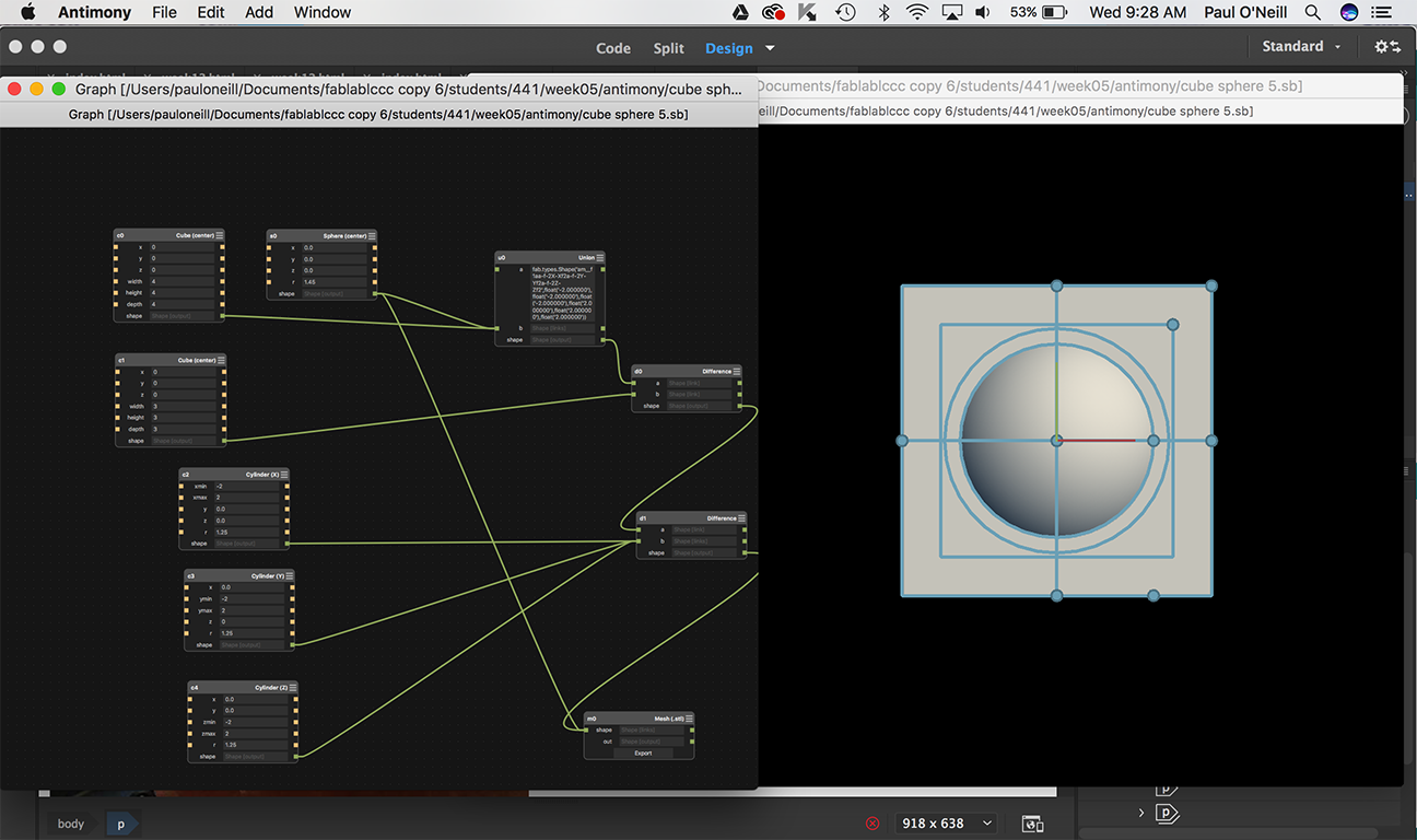
(File for Antimony: cube sphere 5.sb)
(File for 3d Printer: cube sphere 5.stl)
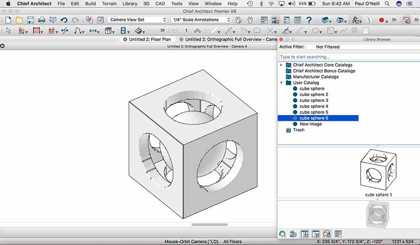
I used Chief Architect to render the STL file model as part of my user library, and then using the object in a plan. Once the object is in a Chief plan, it can be exported to a number of formats, and for me, easily examined and rendered.
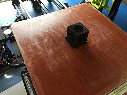
I loaded the STL file into Cura, set the bed temperature to 200 deg.F and the bed temp to 90 deg.F I decided to use black PLA. The TAZ machine only uses 3.0MM filament.
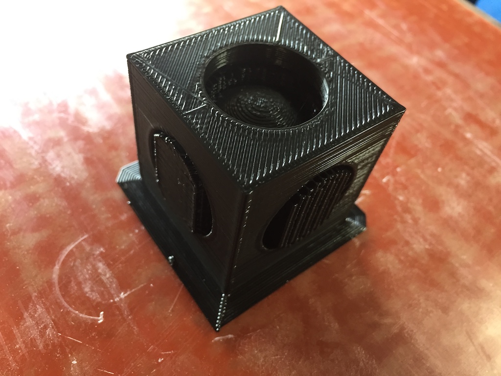
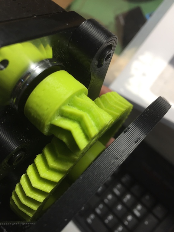
The model took about 3 hours to print. Cura inserted lots of supports around the ball. I used the pliers on my Leatherman tool to weed them out.
I opted to print a raft for the part. In retrospect, I'm not sure if this was necessary.
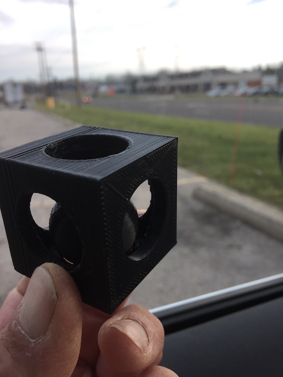
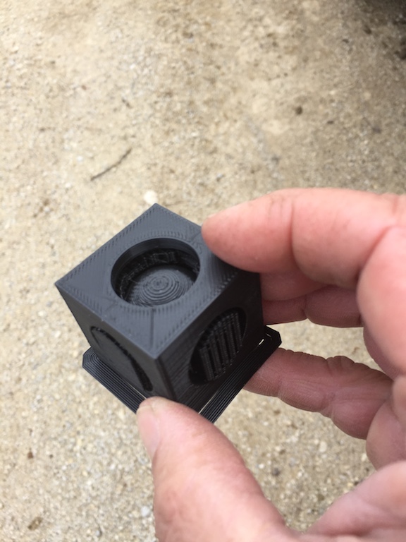
The ball shpere completely weeded out. The ball bounces inside of the cubic cage.
The other part of this week's assignment is to 3D scan an object.
The 3d scanning was not so impressive. The results were huge and erroneous. I have some experience using 3d scanning utilizing an API Laser tracker, having used them for scanning movable bridge parts on live track for Amtrak. In fact, I lectured and demonstrated the API Laser Tracker at the 9th Biannual Heavy Movable Struictures Symposium back in 2002. The API laser tracker uses a prism ball to actually physically contact the part being scanned. I have scanned many movable draw bridges on the Acela high speed rail line, modelling replacement parts for bridges which cannot be taken out of service, and achieved results within 0.003". 3D modelling with a laser tracker allows you to make precision parts without having to remove the part, if you tool properly.
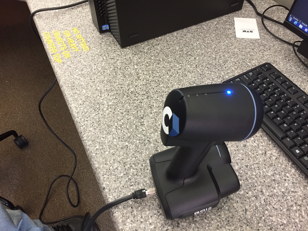
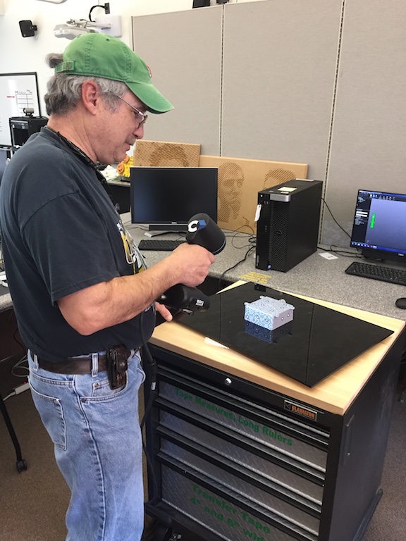
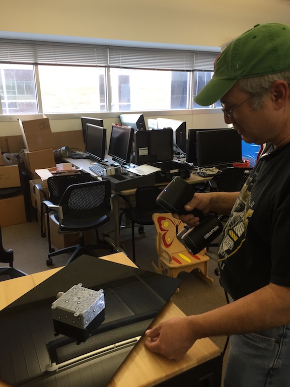
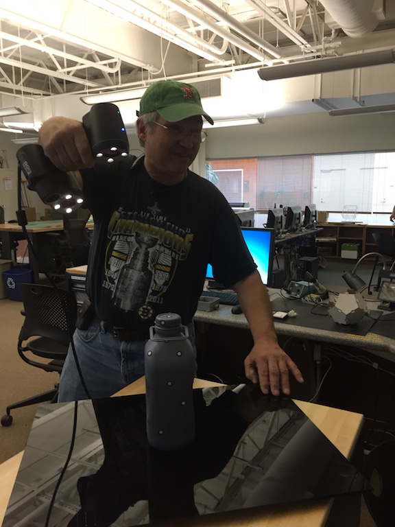
The 3D scanning equipment at LCCC is a Go!SCAN 50 by Creaform. It consists of a handheld laser gun and a rotary table that you place your part on and spin.
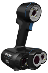
(from Creaform website)
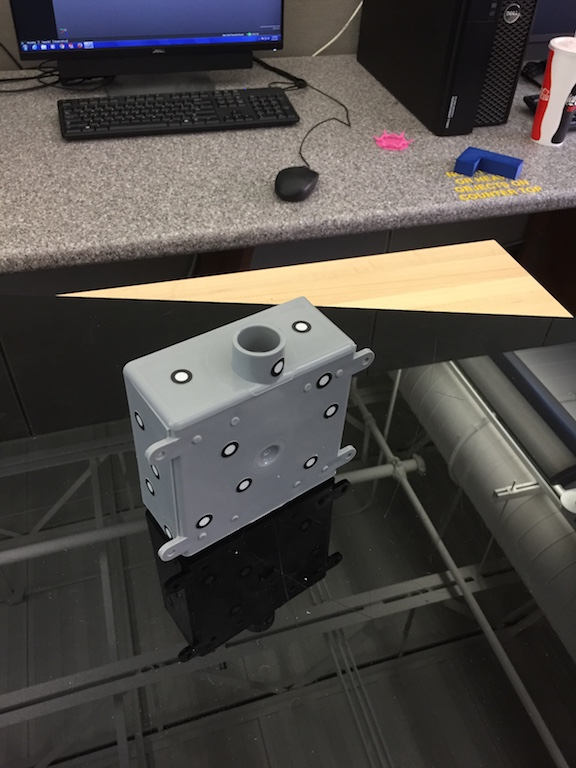
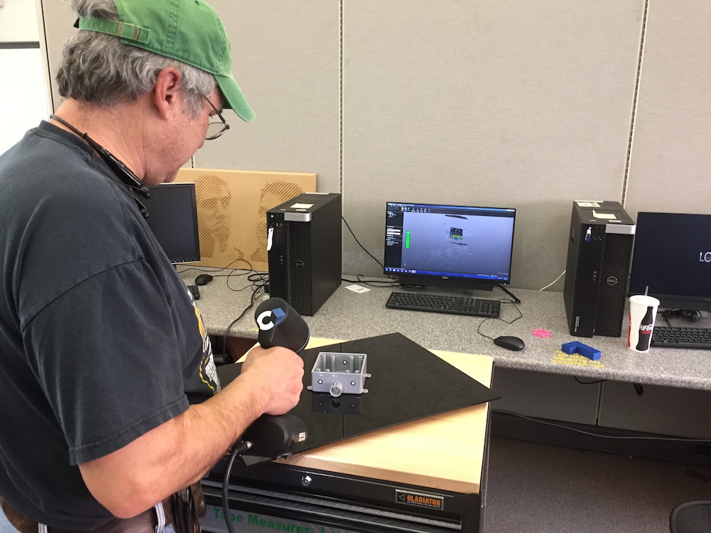
The part I want to scan is a simple electrical outlet box. The outlet box has to be placed on a rotary table.
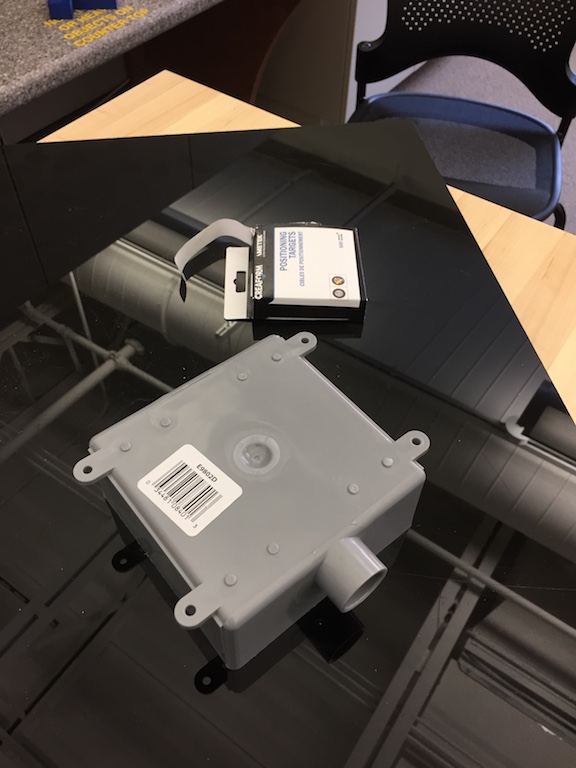
The first thing you must do to prepare the item for scanning is place reflective dots on all surfaces of the part. The manufacturer calls these "Positioning Targets" and they are self adhesive stickers that come in a roll. You should have at least 3 dots at a minimum per surface.
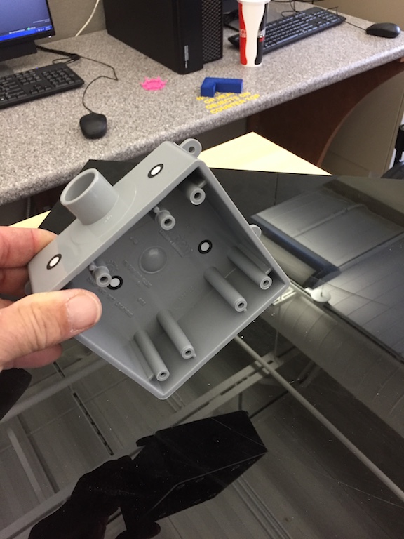
I covered the inside as well as the outside of the box.
After the target is prepared, I connect the scanner with the help of my instructor, Scott Zitek to a desktop computer already configured with the software VXelements. The scanner plugs into an available USB port. There is a calibration plate you must use to calibrate the scanner before you use it on your part.
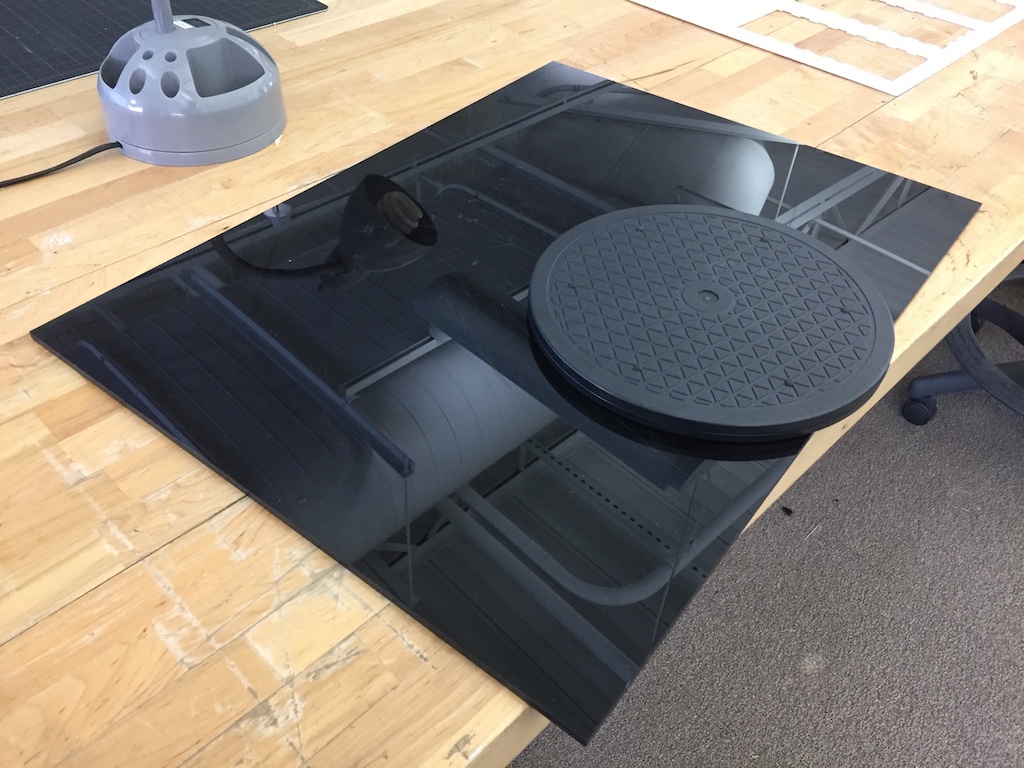
I am provided a lazy susan type device. I'm told the scanner works better with a black background. LCCC lab has available a black piece of plastic to accomplish this. I placed the black plastic sheet on top of the lazy susan to effect a sort of rotary table.
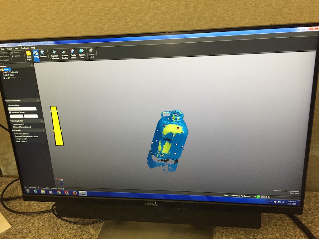
I next placed the part on top of the rotary table. I start up the application VXelements. The application shows you in real time your scanning of the object.
The software lets you reorientate the part and resume scanning.
Here I reorientate the part so the back of the box is facing up.
I continue to spin and scan the part. I was not getting very good results. I asked for help from my instructor.
We tried closing window blinds and turning off lights. I still struggled to get a good representation of this simple part.
I kept repeating the procedure a number of times. I still did not get good results.
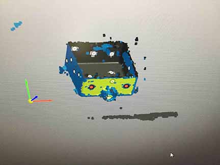
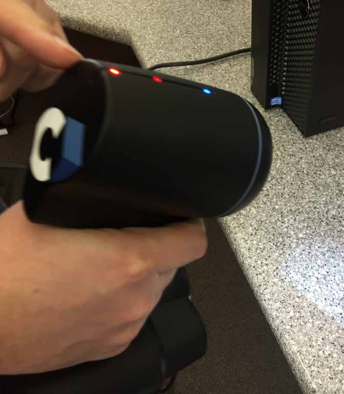
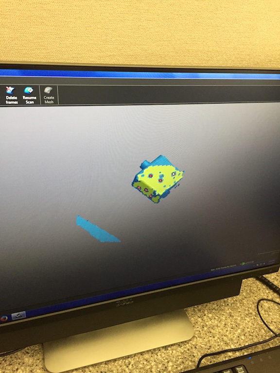
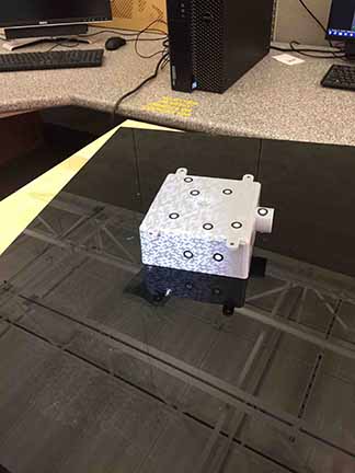
The above is about the best the scanner could do. If the light on the scanner stays green, you are registering and everything is fine. Red liights tell you that you are too close, or too far, and are not locked on the part any longer. Once you have lost your lock on the part, you must go back to an area of the part where you had a lock to reaquire the part.
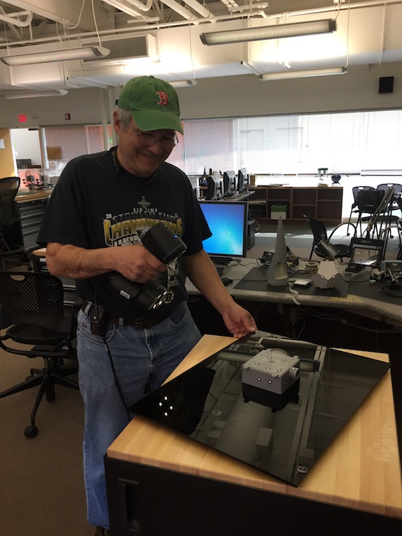
Things were not running well. I asked for more help, and my instructor suggested I try scanning a part which was performed by Chris Rohal from the previous cycle, for troubleshooting purposes.
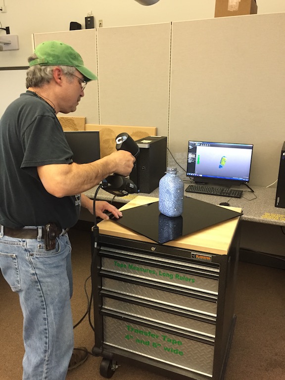
This part was spray painted gray and covered with targets. I followed the same process I followed for the electrical box.
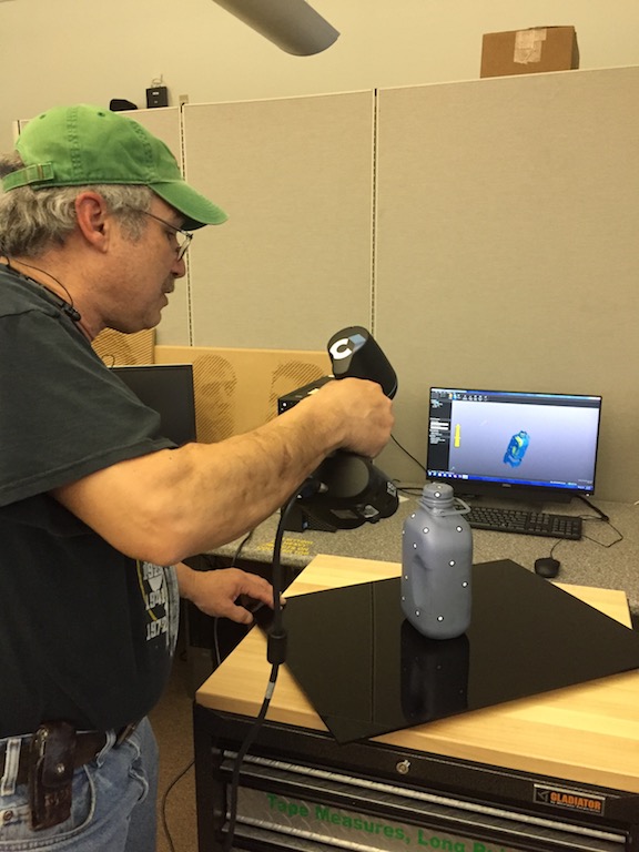
I was still not getting very good results.
Even with the lights out, I kept loosing lock on the part.
I did a little research and learned more about the specs for the GoScan!50. The resolution for the scanner is 0.020 inch and the accuracy is 0.004 inch. Perhaps the wall thickness of the electrical box is too thin for the scanner to keep locked.
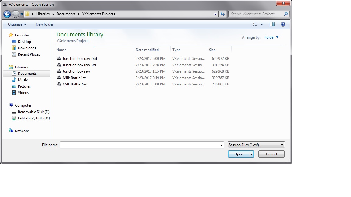 The size of the files generated are too big for the repo. I tried uiploading these to the repo and my access was shut off. The above image is evidence of the files being created and being too big. Neither of the objects scanned properly for me.